Advertisement
Quick Links
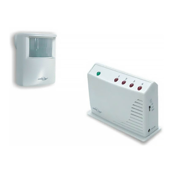
Motion Alert
1. INTRODUCTION
The Motion Alert is designed to monitor movement around your house.
The motion sensor can be placed either indoor or outdoor. Once motion
is detected, the receiver will beep & flash.
In this package, you should find an Indoor/Outdoor Motion Sensor, a
Household Alert
Receiver, an adapter, ball-head joint, screws and a
®
clip.
Ball-head joint
Adapter
2 pcs 3 x 18 screws
(Included)
Please follow the instructions below to setup your motion sensor and
the receiver.
2. SET UP CODE CONNECTORS AND ZONE CONNECTORS
1. CODE CONNECTORS
In order for the sensor to communicate with the receiver properly, the
sensor's code must match with the receiver's code. Code connectors 1
to 6 can be found by opening the battery cover and the back cover of
the receiver. User is required to set these code connectors randomly
and the code settings on the sensor and receiver must be the same.
Each position of the code connector can be set to "+", "-" or "0" position.
Refer to the diagram below to set
the code connectors properly. If the connector
is placed on the top and middle posts, that
column is set on " + ". If the connector is
placed on the middle and bottom posts, that
column is set on " - ". If the connector is
removed completely, (not placed on any posts),
it is set to " 0 ". (see diagram for examples of
how to set a column to the three different
positions).
Code Connectors on Motion Sensor
Code Connectors on Receiver
Note: If you experience interference from a nearby system, which could
accidentally trigger your system, please change the code settings on the
sensor and receiver. The code setting on the sensor and receiver should
still match after changing the code setting.
2. ZONE CONNECTORS
2. SET UP CODE CONNECTORS AND ZONE CONNECTORS (CONT)
Each receiver can work with up to 4 different sensors (to represent 4
different zones on the receiver). There are 2 connectors that determine
the zone number 1, 2, 3 and 4. These 2 connectors can be found by
opening the battery cover. Please follow table 1 to set the zone.
Zone connectors
"+" in the table means the connec tor for that position should be placed on
the posts.
"-" in the table means the connector for that position should be removed.
Model HA-434
Indoor/Outdoor
Motion Sensor
Clip
®
Household Alert
Receiver
'
'
0
'+'
Note: A connector
can be removed
with the clip, as
shown.
A
Zone 1
+
Zone 2
+
Zone 3
-
Zone 4
-
Table 1
3. POWER UP THE HOUSEHOLD ALERT
OUTDOOR MOTION SENSOR
1. POWER UP
After setting up all the connectors properly, both units are now ready to be
powered up.
Insert a 9V alkaline battery (not included) to the motion sensor and its
LED will be on for 2 seconds. The receiver will beep and red LED flash.
The sensor requires a warm up time of approx. 45 seconds before it
can function properly. After powering up the sensor, face it to the wall
where no motion will be detected. After 45 seconds, the sensor is
ready. Wave your hand in front of the sensor, the receiver will beep and
red LED will flash for approx. 15 seconds.
Plug in the adapter to the receiver, the green LED will start flashing
indicating the receiver unit is powered up but no sensor is detected.
Plug in the adapter to the receiver
2. SENSOR SENSITIVITY
The sensitivity of the motion sensor is adjustable. Change the setting by
placing the connector on either the "High" or "Low" position. When the
sensitivity is set to "Low", more movement is required to trigger the
sensor. It is recommended to set the sensitivity to "Low" and perform a
"Walk Test" (Described in Section 3 - "Walk Test"). If the walk test result
is satisfied, the sensitivity does not
require to be adjusted further. If the
walk test result shows the sensitivity
'-'
is too low, then you can change the
sensitivity setting to "High". Please
perform the walk test after changing
the sensitivity setting.
Clip
3. MOUNTING
A ball-head joint is necessary to mount the sensor at a desire location.
A height of 5-6 ft is recommended, depending on your application. Once
a location is selected, mount the ball-head joint to this location by screws
provided, (see diagram 1). Once the ball-head joint is mounted to the
wall, slide the back of the sensor into the ball-head joint (see diagram 2).
The mounting angle can be adjusted. Please refer to Section 3 "Walk
Test" to determine the best mounting angle.
Diagram 1
4. WALK TEST
B
After mounting the sensor at the desired location, it is
+
important to perform a walk test in order to determine
-
if the sensor is detecting the things you want to detect.
+
In order to control how far the sensor can "see", this can be done by
-
adjusting the angle of the sensor. To reduce the detection range, simply
move the sensor downward. To increase the range, move the sensor
up to around 12 degrees. This will give the maximum range. However,
this may not be desired if the sensor is placed outdoors, since a false
trigger may occur if the sensor is set to detect motion in a distance.
®
RECEIVER AND INDOOR/
Insert 9V alkaline battery to the sensor
Sensitivity Connectors on Motion Sensor
Diagram 2
Advertisement

Summary of Contents for SkyLink HA-434
- Page 1 Motion Alert Model HA-434 1. INTRODUCTION 3. POWER UP THE HOUSEHOLD ALERT ® RECEIVER AND INDOOR/ OUTDOOR MOTION SENSOR The Motion Alert is designed to monitor movement around your house. The motion sensor can be placed either indoor or outdoor. Once motion 1.
- Page 2 “single beep”, i.e. “beep” pause, “beep”, pause….. etc. If you would like to order Skylink’s products or have difficulty getting them to work, please : If the sensor is set to zone 4, zone 4 red LED will flash, and the receiver 1.