Advertisement
Quick Links
Siemens Industry, Inc.
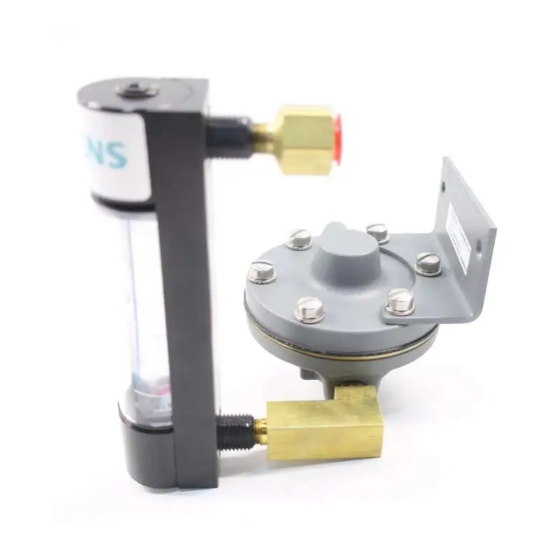
Model Series 62 Constant Differential Relay
INTRODUCTION
The Constant Differential Relay maintains a constant pressure drop across an internal needle valve for any flow
setting up to about 2.1 cubic feet of air per hour. It thus provides a means for maintaining a practically constant
volumetric rate of flow regardless of variations of the process or supply pressures. The differential maintained across
the needle valve is 1 to 2 psig. This permits a greater opening of the needle valve, thus making it less subject to
clogging. The constant differential relay may be used in conjunction with a rotameter type indicator.
The differential applied to the internal needle valve is determined by a spring-loaded diaphragm in the constant
differential relay. This diaphragm controls the action of a valve plunger to automatically admit supply air to the
needle valve at the required rate. A self-contained automatic bleed discharges excess supply air to the atmosphere
when necessary. The constant differential relay is made of aluminum, brass, stainless steel, Neoprene and Buna-N.
The rotameter is constructed of aluminum, stainless steel, borosilicate glass, Buna-N (O-rings), ruby sapphire (float)
and brass (fittings). Neither will be affected by ordinary air line impurities.
This instruction has five major sections: Introduction, Installation, Operation, Maintenance, and Parts List.
Model Designation
Constant Differential Relay
With Built-In Needle Valve
Needle Valve with Tight Shut-Off
Attached Rotameter Piped Assembly
Specifications
Supply Pressure
Minimum................................. At least 5 psig greater than the maximum downstream pressure.
Maximum ................................ 150 psig
Purge Rate:
Maximum
Minimum
Ambient Temperature Limits ................ -40° to +180°F (-40° to +82°C)
INSTALLATION AND SERVICE INSTRUCTION
62
V
N
Models 62V & 62VA
2.1 SCFH
991 SCCM
0.9 SCFH
425 SCCM
A
Models 62VN & 62VNA
1.8 SCFH
0.06 SCFH
1
SD62
Rev 11
March 2011
Supersedes Rev 10
850 SCCM
28 SCCM
Advertisement

Related Manuals for Siemens 62 Series


Summary of Contents for Siemens 62 Series
- Page 1 Siemens Industry, Inc. INSTALLATION AND SERVICE INSTRUCTION SD62 Rev 11 March 2011 Supersedes Rev 10 Model Series 62 Constant Differential Relay INTRODUCTION The Constant Differential Relay maintains a constant pressure drop across an internal needle valve for any flow setting up to about 2.1 cubic feet of air per hour. It thus provides a means for maintaining a practically constant volumetric rate of flow regardless of variations of the process or supply pressures.
-
Page 2: Installation
SD62 INSTALLATION Shipping and Storage If the relay is to be stocked, stored, or shipped to another location prior to piping, make sure that the factory installed plastic plugs are in the ports to prevent entry of moisture, dirt, or other contaminants. Mounting Mounting dimensions and the locations and sizes of the pipe connections are shown in Figures 1 and 2. - Page 3 SD62 Figure 1 Installation Dimensions with Rounded Rotameter...
- Page 4 SD62 Figure 2 Installation Dimensions with Rectangular Rotameter Figure 3 Application Example The requirements for a quality instrument air supply can be found in the Instrument Society of America's "Quality Standard for Instrument Air" (ISA-S7.3). Basically, this standard calls for the following: Particle Size —...
-
Page 5: Operation
SD62 OPERATION With the air supply on, turn the needle valve to obtain the desired flow rate. The best rate will depend on the volume of air in the system and the desired speed of response to level changes. Ordinarily, a rate of 0.9 SCFH (minimum flow for Model 62V) is considered satisfactory, although this may have to be increased to obtain the desired speed of response, particularly if the system contains much volume or is subject to rapid pressure or level fluctuations. - Page 6 Siemens Industry, Inc. assumes no liability for errors or omissions in this document or for the application and use of information in this document. The information herein is subject to change without notice.
-
Page 7: Parts List
* Recommended on-hand spare parts. Always specify range, serial number, and other nameplate information when ordering. IMPORTANT Service Parts Kits are available for servicing the instrument. Contact Siemens for available kits; refer to the Customer/Product Support section of this instruction. Some parts in this Parts List may not be available for separate purchase.