Table of Contents
Advertisement
Quick Links
Advertisement
Table of Contents

Summary of Contents for Acoustic Research Ngara
- Page 1 Ngara User Manual 25-7cd7566...
- Page 2 Juan Aguero Move images to images folder d3798ae 2018-03-05 Juan Aguero Add application history 15aafc7 2018-03-05 Juan Aguero Merge branch ’master’ of git.lab:ngara/logger.wiki 2117605 2018-03-05 Juan Aguero Update to format and spelling 4cb3b86 2018-03-05 Juan Aguero Add header information fbfc9db...
-
Page 3: Table Of Contents
2.3 Ngara ........ - Page 4 Ngara User Manual 4 Local Operation 4.1 Available User Interface ......... . 23 4.2 Powering the Unit .
- Page 5 Ngara User Manual 4.6.6 RMS Detection ......... . 36 4.6.7...
- Page 6 Ngara User Manual 5.4.8 Noise Cloud Configuration ........57 5.4.9...
- Page 7 Ngara User Manual 7.7.1 Frequency Response ........73 7.7.2...
-
Page 8: Introduction
• L In addition to the above measurements the Ngara platform is able to store raw audio data to a USB storage device, capable of post processing the majority of your acoustic needs. All of this is achieved in a low power 12-volt environment. -
Page 9: General Description
2.1 Weather Proof Case Ngara is housed in a rugged weatherproof case. To open the case, unclip the two latches at the front of the case. When closing the weatherproof case, ensure the microphone lead is carefully guided through the cut out provided. -
Page 10: Enclosure Back
• Aux connector (4-pin) • Ethernet communications port (RJ-45) This port can be used to connect to a Local Area Network (LAN) to provide a communications link to Ngara • USB ports (2x USB ports) The USB ports allow the connection of a single storage device •... -
Page 11: Enclosure Top
Wind and rain shields are available as an option for Ngara. Detailed microphone specifications can be found on Section 7.7. - Page 12 Ngara User Manual To make these posts easy to set up and pull apart, we recommend dipping the post screws in a lubricant, such as Vaseline. This makes the posts easier to screw into each other and it also stops them from becoming stuck after being left in the field for a few days.
-
Page 13: Functions
3.1.1 Storage Handling All USB storage devices must be formatted by Ngara. This ensures both, a small format information file is written at the root of the drive as well as circumventing the Windows imposed FAT32 file system allocation size limit of 32GB. -
Page 14: Session Directory
Session information messages, along with any session errors are displayed within the log file. Ngara maintains a copy of this log file in its internal memory. This allows correct error logging, even when access to the USB is not possible. - Page 15 Ngara User Manual Description Wave file sampling frequency (48kHz or 12kHz) WAVE FREQ Wave file number of bits (16bit or 8bit) WAVE DEPTH WAVE RANGING Wave file auto ranging (ON or OFF) TRIG SETTING Triggering setting (ON or OFF) Current trigger type...
-
Page 16: Data Usage
User Manual 3.1.3.3.2 PCM Data Ngara is capable of storing raw audio samples. The raw files can be used in conjunction with FireFly to obtain octave spectrum analysis of the data. More information on FireFly can be found here. PCM samples are stored as single channel data and are taken directly from the microphone output voltage. These samples are used internally during SPL calculations and are sampled by the Analog-to-Digital-Converter (ADC) at a constant rate of 48kHz. -
Page 17: Noise Cloud
Ngara currently requires a writeKey to be entered by the user. This is generated through the Noise Cloud interface and is to be provided to Ngara as part of the Noise Cloud configuration in the Remote Host. See Section 5.4.8. -
Page 18: Operation Settings
3.2.4 Data Usage All data that is uploaded by Ngara is consumed by the Noise Cloud server, this occurs at an hourly rate of 77.1kB Future Noise Cloud development may involve two way communication with Ngara which may increase this base figure. - Page 19 Check Upload Rate (Section 4.8.4) Force upload using Wakeup button Ensure service light on modem flashes Ensure Ethernet light on Ngara flashes Ensure Ngara connectivity set correctly (Section 4.4.3.6) Figure 4: Noise Cloud Troubleshooting Version — 25-7cd7566 Page — 19 of 80...
-
Page 20: Email
3.3.3 Format The email alert provided by Ngara is a simple text email which is appended with each new email alert. This allows for internal buffering of alerts in the event that no communication could be established with the mail server. The general format of each alert email entry is shown below, with details of all values described in Table 11. -
Page 21: Industrial Noise Monitor
3.4 Industrial Noise Monitor When Ngara is configured for Industrial Noise Monitor operation, it provides an additional processing channel. This channel consists of a configurable band pass filter, with the band edges being those defined for 1/3 octave bands and range from 10Hz to 20kHz. -
Page 22: Data Usage
Ngara User Manual 3.4.2 Data Usage Table 13 describes the expected additional data usage when operating in Industrial Noise Monitor mode. These are in addition to those listed in Section 3.1.4. Table 13: Industrial Noise Monitor Additional Data Usage CSV Data... -
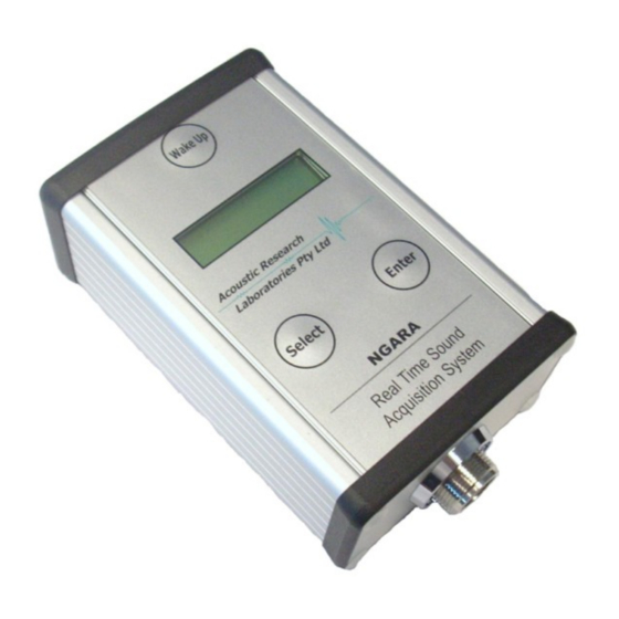
Page 23: Local Operation
Used to select menu items 4.2 Powering the Unit To turn Ngara on, press and hold the wake-up button until NGARA or a firmware version identifier is displayed on the LCD. If the power cable has been unplugged or the Ngara has been turned off, please wait 1 to 2 minutes ... -
Page 24: Idle Timeout
The idle timeout menu item allows toggling of the idle time out setting to either Enabled or Disabled. The timeout length setting is preset to 2 minutes. If this timeout is reached Ngara will power off, if not in recording mode. - Page 25 4. Confirm selection by pressing ENTER 4.4.3.3 IP Address The IP address menu item allows the configuration, or display of the IP address currently configured for the Ngara. To view currently assigned IP address, the following steps must be carried out - 1.
- Page 26 Description WR11 Modem Ngara is connected to WR11 modem Ngara is connected to an Local Area Network LAN Direct LAN To change the IP mode of operation, the following steps must be carried out - 1. Activate menu item by pressing ENTER 2.
-
Page 27: Time And Date
3. Toggle setting using SELECT 4. Confirm selection by pressing ENTER Configuring to use the WR11 modem will allow Ngara to interrogate the modem to determine if valid internet access is provided. Direct LAN setting should be used when the Ethernet interface is always on, and no modem is in use. -
Page 28: Temperature Calibration
This menu item is not accessible when in recording mode. 4.4.6 Temperature Calibration Allows Ngara to calibrate its internal temperature sensor. The internal temperature sensor is used to monitor the performance of the electronics within the weatherproof enclosure and it is not intended to replace weather station data. -
Page 29: Keep Alive
The keep alive menu item allows the setting of the internal Real-Time-Clock (RTC) daily alarm. It can be set to either On or Off. When set to On, the RTC alarm is configured to generate a wake-up signal at 7am each day. This ensures Ngara powers up in the event it lost power. -
Page 30: Exit
As this session is started through the local interface instead of a remote PC, the session name cannot be entered, thus Ngara creates a name based on current date and time. A session will not be able to be started if any of the following conditions are met: •... -
Page 31: Stop Session
Upon selection of this menu item, a Session Flushing message will appear on the display to indicate final flushing of data to disk is taking place. Upon completion of the data flushing, Ngara will return to the top-level menu structure. -
Page 32: Change Disk
To swap a USB storage device using the LCD, the following steps must be carried out - 1. Activate menu item by pressing ENTER 2. Ngara will indicate the internal buffers are being flushed to disk by displaying “Session Flushing” 3. A Swap Disk message appears once the internal buffers have all been written to disk. -
Page 33: Trigger Setup
IEC 61260 for 1/3 fractional octave bands, ranging from 10Hz to 20kHz. To change selected bands, the following steps must be carried out – 1. Activate menu item by pressing ENTER 2. Ngara will display current Low Band setting 3. Toggle setting using SELECT 4. Confirm selection by pressing ENTER Version —... -
Page 34: Flush Logs
1. Activate menu item by pressing ENTER 2. Ngara will display an error message if an error was encountered A valid drive must be inserted into Ngara’s USB port in order to successfully flush internal log files This menu item is not accessible when a USB session is running, or if no internal log files are found. -
Page 35: Show Status
Ngara User Manual 4.6.1 Show Status This menu item scrolls through current logger operation, configuration and errors (if any). Refer to Section 4.9 for details of all possible screens. Within this menu screen - • Pressing SELECT will scroll through each item. -
Page 36: Long L
Ngara User Manual 4.6.5 Long L Displays current Time Averaged L . Both A and C weighted. Averaging starts once menu item is entered. An overload condition is indicated with an ‘^’. Within this menu screen: • Pressing SELECT will re-start the averaging time and reset any overload condition •... -
Page 37: Disk Menu Item (Menu 4)
Ngara User Manual 4.7 Disk Menu Item (Menu 4) Items available through the disk menu give the ability to update and configure USB devices. 4.7.1 Disk Status This menu item displays the current USB disk state. Allowable states are listed on Table 18. -
Page 38: Format Disk
Noise Cloud is taking place. Upon successful connection to the server, a countdown showing the number of records remaining appears. After completion of the data flushing, Ngara will return to the top-level menu structure. To stop a Noise Cloud session using the LCD, the following steps must be carried out - Version —... -
Page 39: Percentiles
1. Activate menu item by pressing ENTER 2. Ngara will indicate the internal memory is being flushed to the Noise Cloud server 3. Once the internal memory has been cleared, the LCD will return to the top level menu item. -
Page 40: Exit
The idle screen is displayed when the following occurs: • Through the Show Status menu item, or • Ngara is idle for more than 120 seconds, or • A connection to the Remote PC application is found The screen circulates through current logger information and displays any warnings or errors that may be present. - Page 41 Ngara User Manual In addition to general status screens, Ngara will also display details of any warning event that may have occurred. Details of these warning screens are shown in Table 21. Table 21: Ngara Warnings Name Description Example RTC Battery...
-
Page 42: Remote Operation
Ngara User Manual 5 Remote Operation The Ngara noise logger provides remote interfacing capabilities through the use of specialised software allowing the user to - • Configure logging parameters • Configure triggering and alarm parameters • Start/Stop logging sessions • Display current configuration information •... -
Page 43: Main Screen
Ngara, see Section 4.4.3. If the Ngara can be accessed within a local network, and is set to DHCP mode (See Section 4.4.3.2), Ngara may also be accessed using the following address name ngara-XXXXXX. Where XXXXXX is the unit’s serial number. This name is then resolved to an IP address by the DHCP server, thus saving the need to remember IP address numbers. -
Page 44: The Result Group
Ngara User Manual 1. Enter the loggers IP Address in the IP Address box 2. Press the Link Button 3. A password prompt will appear 4. Enter loggers remote password as previously set in Section 4.4.3.1 5. Connection will be established To disconnect from a remote logger - 1. -
Page 45: Changing Logger Configuration
File -> Logger Configuration -> Change Configuration Figure 6: Logger Configuration Menu 5.4.1 General Logger Configuration Tab Ngara configuration tab allows general configuration changes to be made. Details of each configuration option is listed on Table 22. Figure 7: Main Logger Configuration... -
Page 46: Wave File Configuration Tab
Ngara User Manual 5.4.2 Wave File Configuration Tab The wave file configuration tab allows the updating of PCM storage. Details of each configuration option is listed in Section 3.1.3.3.2. Figure 8: Logger Configuration Menu 5.4.3 Trigger Configuration Tab PCM data triggering modes can be adjusted through the Trigger Parameters tab. - Page 47 In the above example a level of 60dB-A must be reached for 5 seconds before triggering is asserted. When trigger is set, 30 seconds of internal buffered data is recorded. The trigger is reset when the level falls below 60dB-A for more than 5 seconds. Once reset Ngara records a further 20 seconds of raw data.
- Page 48 Ngara User Manual Figure 10: Level trigger example 5.4.3.2 Setting an SPL or L Percentile Trigger Ngara can be set to continually monitor the current percentile levels over a given time period. Version — 25-7cd7566 Page — 48 of 80...
- Page 49 When trigger is set, 30 seconds of internal buffered data is recorded. This buffer can be set to a maximum of 480seconds (8 minutes) Once the L falls below 60dB-A, Ngara records a further 20 seconds of raw data. Version — 25-7cd7566 Page — 49 of 80...
- Page 50 Ngara User Manual Figure 12: Percentile Trigger Example 5.4.3.3 Setting an RMS Trigger (For Engine Brake Analysis) The following example illustrates to set an engine brake trigger. Version — 25-7cd7566 Page — 50 of 80...
- Page 51 Figure 13: RMS Trigger Example In this example, Ngara will set a trigger event as soon as the RMS is greater than 3.12. It will then record 7 seconds of internal buffered data, followed by 8 seconds of raw data after the trigger event.
- Page 52 Ngara User Manual Figure 14: RMS Trigger Example 5.4.3.4 Setting a Time Based Trigger The following example illustrates how to set time based wave file recording. Version — 25-7cd7566 Page — 52 of 80...
- Page 53 Figure 16: Push Button Trigger Example Ngara will trigger and record a wave file for the pre and post time periods once it detects a push button trigger event. This requires an internal modification for Silver (V1) Ngara and cannot be used at the same time as the ...
-
Page 54: Alarm Clock Tab
5.4.4 Alarm Clock Tab Ngara is capable of setting an alarm clock that may be implemented to conserve battery power. It can be set up to power itself on, log for a certain time period, and turn itself off. The settings for the logging session may be set up using any of the previous tabs. -
Page 55: Udp Output Tab
Ngara is capable of sending results information to listeners via User Datagram Protocol(UDP). Figure 19: UDP Output Configuration The IP address and port number is the “SEND TO” address that the Ngara unit will channel the information into. Version — 25-7cd7566... -
Page 56: Advanced Configuration Options
Using IP address “255.255.255.255” will cause Ngara to send broadcast messages to all network devices The output data can only be set to only one of the 5 results that Ngara calculates, along with the optional raw data sample values. -
Page 57: Noise Cloud Configuration
All L that will be pushed to Noise Cloud 5.4.9 Email Tab Ngara email tab allows users to set L and L levels which will trigger an event email., The email will detail the time at which the given level was reached and at what level. Up to 5 email addresses can be listed. -
Page 58: Logger Time
Ngara User Manual Figure 21: Email Alert Configuration From firmware V 12.1 Ngara now has access to email servers hosted by Acoustic Research Labs, as such, server and from fields are not accessible. 5.5 Logger Time Logger time can be updated by navigating to the following menu item. -
Page 59: System Calibration
Ngara User Manual Figure 23: Set Time Configuration The date, time and timezone information can be entered manually, alternatively, the PC Time button provided can be used. This will set the current date, time and timezone information to match that of the controlling PC. -
Page 60: Logger Reboot
A steady signal must first be detected before the OK button is enabled 5.7 Logger Reboot For logger versions V 7.06 and later, it is possible to remotely reboot the Ngara by navigating to the following menu item File -> Reboot... -
Page 61: Logger Control
Ngara User Manual Figure 27: Logger Sleep Ngara waits for any running USB and Noise Cloud operations to stop before shutting down 5.9 Logger Control Main logger control is achieved through the Session Control menu item. Through this menu item it is possible to do any one of the following •... -
Page 62: Stopping A Session
Figure 30: Stopping a Session Indication of the stop session command can be viewed through the logger’s status information group described in Section 5.3.2. The internal buffers must be flushed before Ngara returns back to the standby state 5.9.3 Taking a Reference Level Reference levels can be recorded to the log file by navigating to the following menu item Session Control ->... -
Page 63: Changing Disk
A secondary window will pop up giving the user a change to confirm or re-take the reference level. Figure 32: Reference Level Confirmation Ngara does not prompt the user to take a reference level at any stage of the logging session. ... -
Page 64: Disk Operations
• Perform statistical analysis on 100ms session date • Re-constitute Wave Files • Re-Format Ngara Drive 5.10.1 Detail Storage Media View A detailed view of the current USB storage device can be seen by navigating to the following menu item Disk ->... -
Page 65: Downloading Session Data
Ngara User Manual 5.10.2 Downloading session Data Session data can be downloaded visa the Ethernet interface by navigating to the following menu item Disk -> Download Session Stats Figure 35: Download Statistics Only the CSV files can be downloaded using the remote user interface, as the downloading of raw audio files would create excessive network traffic. -
Page 66: Remotely Formatting A Usb Drive
Disk -> Remote Format Figure 37: Remote Disk Format 5.10.4 Performing Statistical Analysis A Ngara session directory (100ms CSV files) can be converted to a statistical representation of the data by navigating to the following menu item Disk -> Gather EL-XXX Statistics Figure 38: USB Statistics Version —... -
Page 67: Re-Constitution Of Wave File Data
USB disk used to record the session. Figure 39: Statistics Configuration 5.10.5 Re-constitution of wave file data A Ngara session directory containing both CSV and PCM data can be scanned, with all range switching removed from PCM files. Disk -> Reconstitute Wave Files Figure 40: PCM Reconstitution The recorded 48kHz wave files are linear from the noise floor of the instrument to approximately 97dB @ 1kHz. -
Page 68: Reformatting A Usb Device
5.10.6 Reformatting a USB Device Figure 41: USB Reformat A drive which has been previously formatted by a Ngara can be re-formatted using a PC. This clears all data on the drive and updates the drive format information file. A drive must always be first formatted using Ngara. -
Page 69: Network Configuration Options
Set to auto configure. Linking to Ngara is then achieved by entering the IP address allocated to the unit. The address allocated by Ngara can be viewed through the LCD, refer to Section 4.4.3.3. See Section 5.3 for details on using the Remote Host application to link to a Ngara. -
Page 70: Connection To A Network
Special care must be taken in setting up the network settings on Ngara to ensure there are no conflicts with other devices on the network. The simplest way to achieve this is to set Ngara to DHCP IP mode. See Section 4.4.3.2. - Page 71 These will ensure all configuration requirements are met. It is also a requirement that all remote 3G/4G Ngara systems be fully operation before they are provided to you. This ensures all systems, including SIM cards, are tested using both the Acoustic Research Labs network and your network.
-
Page 72: Reference Specifications
Calibration is performed using the Remote Host software (Section 5.6) or via the on-board push button interface (Section 4.4.5). Recommended calibration components – • Acoustic Calibrator – NC-74 Using the above calibrator a reference tone at 94dB (A) is equal to 94.00dB (A) as seen by Ngara. Version — 25-7cd7566 Page — 72 of 80... -
Page 73: Extreme Inputs
∼ 11V Maximum Electrical Input Minimum Supply Voltage 10.8V Maximum Supply Voltage 7.6 Nominal A-Weighted Sound Levels Table 31: Nominal A Weighted Response Frequency (Hz) Ideal (dB) Ngara (dB) Difference (dB) Tolerance (dB) ±2.0 31.5 39.4 39.7 ±1.1 1 000 ±1.6... -
Page 74: Directional Response
The directional characteristic of a microphone is a measure of its differing sensitivity for sound waves arriving from various angles. Since the pre-polarised condenser microphone used in Ngara is a pressure sensitive type, it should be equal in all directions. However, refraction and cavity effects cause a certain microphone directional response at high frequencies. -
Page 75: Humidity Characteristics
Ngara User Manual Figure 44: UC-53A Thermal Response 7.7.4 Humidity Characteristics The humidity characteristics of a microphone indicate how sensitivity changes at various humidity levels. Figure 45 shows the humidity characteristics for a UC-53A microphone at 250Hz. Figure 45: UC-53A Humidity Response 7.7.5 Reduction of Wind Noise by Windscreen... -
Page 76: Specifications
Ngara User Manual Figure 46: Windscreen Noise Reduction Figure 46 shows the influence of windscreen WS-10 on acoustical properties of microphone (referred to microphone response without windscreen). The influence of the windscreen WS-10 on the acoustic performance of the microphone is within +/-1.0dB up to 12.5 kHz. - Page 77 Ngara User Manual Figure 47: 10Hz to 1kHz Version — 25-7cd7566 Page — 77 of 80...
- Page 78 Ngara User Manual Figure 48: 10Hz to 10kHz Version — 25-7cd7566 Page — 78 of 80...
- Page 79 Ngara User Manual Figure 49: 1kHz to 10kHz Version — 25-7cd7566 Page — 79 of 80...
-
Page 80: Application Change Log
Ngara User Manual 8 Application Change Log Revision History Revision Date Author(s) Description v9.4.2 2014-07-16 Juan Aguero update to flash filesystem value checks and ip address quad han- dling v10.0 2015-05-04 Juan Aguero As released with V2 boards. v10.0.1 2015-05-05...