Table of Contents
Advertisement
Quick Links
Advertisement
Table of Contents

Related Manuals for Panasonic BT-LH1770P


Summary of Contents for Panasonic BT-LH1770P
- Page 1 OMB1770-U-2...
- Page 2 CAUTION RISK OF ELECTRIC SHOCK DO NOT OPEN. SA 1965 SA 1966 CAUTION: TO REDUCE THE RISK OF ELECTRIC SHOCK, DO NOT REMOVE COVER (OR BACK). NO USER-SERVICEABLE PARTS INSIDE. REFER SERVICING TO QUALIFIED SERVICE PERSONNEL. The lightning flash with arrowhead inside a triangle is intended to warn the user that parts inside the product are dangerous and many cause electric hazards.
-
Page 3: Important Safety Instructions
IMPORTANT SAFETY INSTRUCTIONS 5) For added protection for this television equipment 1. General during a lightning storm, or when it is left 1) Read all instructions provided. unattended and unused for long periods of time, 2) Save these instructions for future use. unplug it from the wall outlet. - Page 4 5) If an image of extremely high brightness is 4) For repair service, contact Panasonic’s authorized displayed on the screen for a long time, the panel sales representative or Panasonic service desk may get burned in.
-
Page 5: Precautions For Operations
In voltage range marked on its back. such cases, contact the Panasonic service desk. 4) If cabinet or screen is dirty, wipe with soft cloth. 9) Should this unit fail within one year after delivery,... -
Page 6: Precautions Upon Use
Precautions Upon Use In order to use the monitor safely, read through this manual and pay attention to the following points in particular. 1. Do not use any power supply other than the specified one (AC/DC). 2. Do not give a shock to the monitor. Be very careful to keep the monitor from shocks because glass is used inside the LCD. - Page 7 8. Avoid operation at low temperatures. The response speed of the liquid crystal decreases as the temperature decreases. Therefore, it is recommended to use the monitor at room temperature. 9. Caution for condensing. When the monitor is used in the condition where temperature abruptly changes, the surface of outside and the inside of monitor are possible to get condensed.
- Page 8 The brightness of the backlight may be reduced in order to keep the internal temperature of the motor from rising. If the message "FAN ERROR!" is displayed, contact your dealer or Panasonic service desk. Accessories The monitor comes with the following accessories. Be sure that they are included.
-
Page 9: Table Of Contents
10. External View ............64 Functions and Making Settings . (USER MARKER) ..29 ........64 4-8. Description of MENU-CAPTURE Functions (1) BT-LH1770P (without stand) ..34 ............65 4-9. Description of MENU-UTILITY Functions (2) BT-LH1770P ..37 ........65 4-10. -
Page 10: Outline
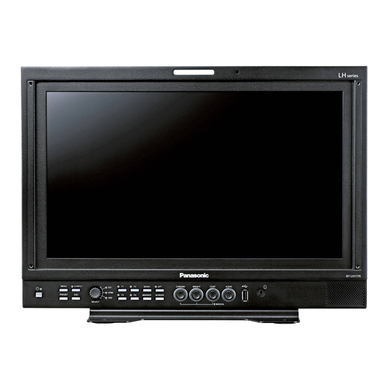
BT-LH1770P LCD Video Monitor 1.Outline 1-1.Outline The monitor also has a standard embedded audio level meter display on the screen. This monitor has a 17-inch full HD LCD panel aiming to reduce the thickness, weight and power consumption, and is a HDTV/SDTV multi-format... - Page 11 the PRESET data, and the full capture image (9) Time code display function data) can be stored on the USB memory for data It is possible to display the time code management on the PC. All these data can be (VITC/LTC) multiplexed into 3G/HD SDI signal copied onto another monitor.
- Page 12 the corner of the screen (small enough not to dis- (21) UMD/IMD display with user display turb the image) so that you can check if there is Sets a material name (alphanumeric) with up no "black sun" effect caused by the brightness to 8 characters to individual monitor for each in- adjustment while looking at the image.
-
Page 13: Names Of Parts And Their Functions
2.Names of parts and their Functions 2-1.Front Controller Parts ○ ○ ① ② ⑤ ⑥ ⑦ ⑯ ⑰ ⑱ ⑲ ⑧ ⑨ ⑫ ⑭ ⑳ CHROMA BRIGHT CONT AUDIO MENU S-INPUT MONO HDMI MARKER SCREEN PRESET SELECT MANUAL ⑩ ⑮ ③... - Page 14 ⑥ Rotally Encoder (RE) <TEST SIGNAL PICTURE> a) Push - 6.8% - 6% - 4% - 2% ・Switching the input signals + 2% 0%~100% Gray scale - 2% Short press RE when MENU display is OFF, to display the switch menu for input signals. 100% 102% 104% 106% 108% 109% <Gray scale with pluge>...
- Page 15 ⑮ SCREEN switch c) Rotating ・ Press this switch to display images in R, G or B ・Rotate the switch while MENU is displayed to individually. select items. ・ The switching between colors takes place as fol- ・This switch is used for drawing USER MARKER, lows each time this switch is pressed.
- Page 16 ・ Connect a USB mouse, and the user markers Speakers can be drawn. ・ Analog audio signals, embedded audio signals and downmix audio signals are fed out of this Stereo headphones output (stereo mini-jack terminal. type) ・ The analog and embedded inputs can be selected ・...
-
Page 17: Rear Panel (Left)
2-2.Rear panel (left) ① ④ DC IN 12V ② AC IN 100-120V 200-240V ③ ① DC input ◆PRECAUTIONS ・ Insert the provided DC cable here to supply DC ・When using the external DC power supply, be sure +12V power. to check the rating of the external DC power sup- ply, and use one that is compatible with this ma- ②... -
Page 18: Rear Panel (Video Inputs/Outputs)
2-3.Rear panel (video inputs/outputs) 3G/HD/SD RS-485 CH A ⑥ ① CH B CH C /OUT1 ⑦ ② CH D /OUT2 PARALLEL REMOTE ③ ⑧ ④ AUDIO ⑤ ① SDI A/B signal input ⑤ Analog audio input ・ Input the 3G/HD-SDI or SD-SDI (4:2:2) signal ・Feed analog stereo audio signals here. -
Page 19: Markers
3.Markers 3-1.Types of Markers In the 16:9 aspect ratio display mode (HDTV/SDTV) In the 4:3 aspect ratio display mode (SDTV) (1) Safety marker (9) Safety maeker Active screen aria Active screen aria (4:3) 100% area 100% area Variable from 80% to Variable from 80% to 99% (1% increments) 99% (1% increments) -
Page 20: Menu Functions
4.MENU Functions 4-1.Flow of MENU Operations Normal screen MENU Long Long pressing pressing INPUT <INPUT> INPUT <VIDEO> MENU VIDEO VIDEO SOURCE SDI CH-A VIDEO VIDEO SOURCE SDI CH-A AUDIO SOURCE SELECT EXECUTE AUDIO SOURCE SELECT EXECUTE TC/WFM/VSC SDI CH LOCK CH LOCK TC/WFM/VSC MARKER... -
Page 21: Description Of Menu-Input Functions
4-2.Description MENU-INPUT Functions INPUT <INPUT> ① VIDEO VIDEO SOURCE SDI CH-A <SORCE SELECT> ② AUDIO SOURCE SELECT EXECUTE SDI CH-A ○ ENABLE ③ SDI CH LOCK TC/WFM/VSC SDI CH-B ○ ENABLE ④ MARKER HDMI(DVI)FORMAT SDI CH-C ○ ENABLE ⑤ CAPTURE RGB RANGE AUTO SDI CH-D... - Page 22 * The TEST signals do not work. ◆Wipe(V) (The ratio is displayed at the top of the * If the main screen and sub screen are connected to screen) HDMI, the video of the sub screen will not be dis- WIPE 70%:30% played MAIN SCREEN...
- Page 23 ◆IN / OUT B * Only SDI signals are supported. SDI CH-C:input ・Default setting is OFF. SDI CH-D:CH-B output OUT B ◆IN / OUT C SDI CH-C:input SDI CH-D:CH-C output OUT C ◆IN / OUT ABC SDI CH-C:input SDI CH-D:CH-A/B/C output Mon OUT ・Default setting is OUT AB.
-
Page 24: Description Of Menu-Video Functions
4-3.Description of MENU-VIDEO Functions INPUT <VIDEO> ① VIDEO CHROMA GAIN UP ② AUDIO GAIN UP SELECT 12dB ③ TC/WFM/VSC SCAN MODE NORMAL ④ MARKER REAL SCAN ⑤ CAPTURE ASPECT MODE 16:9 ⑥ UTILITY ASPECT REFERENCE INPUT ⑦ FUNC.SW PC ASPECT NORMAL ⑧... - Page 25 ⑥ Setting the ASPECT REFERENCE Vertical screen position adjustment ⑨ ・Used to select the automatic setting of a preset Adjust the vertical screen position of the input ・ aspect ratio or the fixed setting for all reception signal in the range of -20 to +20. channels, when selecting any reception channel.
- Page 26 ⑮ Executing the 2x/4x zoom function ・A function used to enlarge the image 2x or 4x without screening. ・You can check for any scratch on the CCD of camera or for the delicate images. * Supported formats are only 720p, 1080i / p. ・The display area to be enlarged is displayed on the left bottom of the screen.
-
Page 27: Description Of Menu-Audio Functions
4-4.Description of MENU AUDIO Functions INPUT <AUDIO> ① VIDEO LINE/SP CH. CH1/2 ② AUDIO SP INPUT SEL AUTO ③ LEVEL INDICATOR TC/WFM/VSC ④ MARKER MODE 1 ( 1 3 5 7 ? 2 4 6 8 ) ⑤ CAPTURE CHANNEL CH1-8 ⑥... - Page 28 ・MODE5 (1357-2468) ⑦ Setting the peak hold display of audio level meter MODE 5 ・Used to turn on and off the peak hold display. CH 1 CH 2 CH 3 CH 4 ・Default setting is ON. CH 5 CH 6 CH 7 CH 8 ⑧...
-
Page 29: Description Of Menu-Tc/Wfm/Vsc Functions
⑯ Setting the embedded audio channel assignment of speaker (Rs) ・Set the channel of embedded audio, which the audio for 5.1ch surround Rs speaker (right side in rear) should be assigned from. ・Default setting is CH6 4-5.Description of MENU-TC/WFM/SC Functions * TC is compatible only with SDI signal (except SD-SDI). - Page 30 ⑬ Setting the VECTOR SCOPE display position ・Used to set the waveform display to any of the RIGHT, CENTER and LEFT positions. ・When used commonly with WFM, the VECTOR CENTER RIGHT LEFT display is located on the left of the WFM one. ・In the case of "RIGHT"...
-
Page 31: Description Of Menu-Marker Functions
4-6.Description of MENU-MARKER Functions <SCENE NAME> <SETTING OF USER MARKER> INPUT <MARKER> PAGE1 ① NO.1 SCENE1□□ VIDEO MARKER(16:9) SAFETY SCENE NAME SCENE1 ② AUDIO SAFETY AREA NO.2 SCENE2□□ SW COL DATA(X ③ ASPECT TC/WFM/VSC NO.3 SCENE3□□ ■ S:--- ---- ④ MARKER AREA IN ASPECT NO.4 SCENE4□□... - Page 32 ・ASPECT : Displaying the aspect marker ⑨ Setting the aspect marker shadow level preset in Item ⑦. ・ Used to set the contrast level of the aspect marker ・C.CROSS : Cross marker. shadow, when displayed. ・CROSS5 : 5-split crosshatch pattern. ・Settings: 0%, 20%, 40% and 60% ・CROSS10 :...
- Page 33 ⑮ Executing the user marker for the drawing set- ・ The name of each scene can be up to 8 characters in ting menu length with the following characters: "0-9, A-Z, (), ・Press RE with EXECUTE, and the user mark- -, □...
- Page 34 4-7.Description of MENU8-15 (USER MARKER) Functions and Making Settings <PAGE1> <PAGE2> ② ④ ③ ① ⑤ <SETTING OF USER MARKER> <SETTING OF USER MARKER> <SETTING OF USER MARKER> PAGE1 PAGE1 PAGE2 SCENE NAME SCENE NAME SCENE1 SCENE1 SW COL DATA(X SW COL SW COL DATA(X...
- Page 35 ●Resetting the data Accordingly, in drawing a horizontal line, the Turn RE in counter-clockwise several times Y-direction address has a coordinate value with while “DATA(X Y)” in ⑤ is flashing to reset 3pixel added, as shown below. the data that have been set to unregistered status (-).
- Page 36 How to preset new user markers X axis ① Setting the marker display ON/OFF ⑤ Setting the start point With nothing registered, the <MARKER> START POINT(X : 0690 , Y : 0540) initial X-Y MARKER(16:9) SAFETY END POINT (X : 0960 , Y : 0540) coordinate is displayed, and SHADOW LEVEL...
-
Page 37: User Marker
How to modify the user markers X axis ⑤ Setting a new start point ① Setting the marker display ON/OFF The start-point START POINT(X : 0300 , Y : 0250) X-Y coordinate <MARKER> END POINT (X : 1200 , Y : 0500) MARKER(16:9) SAFETY starts blinking. -
Page 38: Description Of Menu-Capture Functions
4-8.Description of MENU-CAPTURE Functions INPUT <CAPTURE> ① VIDEO SCR CAPTURE EXECUTE ② AUDIO AREA FULL ③ FULL CAPTURE EXECUTE TC/WFM/VSC ④ MARKER CHG MANUAL EXECUTE ⑤ CAPTURE CHG AUTO EXECUTE ⑥ UTILITY INTERVAL FUNC.SW <TO USB MEMORY> ⑦ P.REMOTE FILE NO. ⑧... - Page 39 * When the power is turned OFF, the captured ⑥ Setting up the interval of the automatic switch- image will be lost. If it is desired to save it for ing mode future use, follow item ⑧ to store it in the USB ・This operation is possible after the full capture memory, and download it from the memory when mode described under item ③...
- Page 40 Concerning dates used for stored files ⑦ Setting the file number of the full capture image ・This feature is used to specify the file number Since the monitor does not have any built-in clock, (1~100) to be used when storing a full capture “the date,”...
- Page 41 How to write of full capture data from monitor to USB memory <CAPTURE> ◆Precaution SCR CAPTURE EXECUTE FULL AREA ・Do not draw out the inserted USB memory FULL CAPTURE EXECUTE Setting the file number to until the writing has been completed. If drawn CHG MANUAL EXECUTE CHG AUTO...
- Page 42 How to download full capture data from USB memory to monitor ◆Precaution <CAPTURE> Setting the file number to SCR CAPTURE EXECUTE ・Do not draw out the inserted USB memory write in to USB memory. AREA FULL until the writing has been completed. If drawn FULL CAPTURE EXECUTE If the broadcast format of...
-
Page 43: Description Of Menu-Utility Functions
4-9.Description of MENU-UTILITY Functions INPUT <UTILITY> ① VIDEO CONT VR ASSIGN CONT ② AUDIO CONTRAST RANGE NORMAL ③ TALLY TC/WFM/VSC ④ MARKER OSD TRANSPARENT ⑤ CAPTURE FORMAT DISPLAY 3SEC ⑥ UTILITY SYSTEM LOCK EXECUTE ⑦ FUNC.SW BATTERY TYPE AC/Ext. P.REMOTE RETURN <LOCK ALL/PRESET>... - Page 44 :AC or external stabilized DC power ⑤ Setting the FORMAT DISPLAY ・AC/Ext. ・Used to set whether the channel and signal format supply are displayed or not. ・DC+14.8V : Battery with nominal voltage of ・3SEC ON :Three seconds indication 14.8V or 14.4V ・CONT ON :Consecutive indication ・DC+13.2V :...
- Page 45 ⑧ Setting the SYSTEM LOCK Contents of LOCK MODE ・How to set a password :The lock is released and all data ・UNLOCK can be changed. ・PRESET LOCK:The PRESET MENU setting of INPUT <UTILITY> item 5 is locked. VIDEO CONT VR ASSIGN CONT ・ALL LOCK :...
-
Page 46: Description Of Menu-Func.sw Functions
4-10.Description of MENU-FUNC.SW Functions INPUT <FUNC.SW> ① VIDEO FUNCTION1 MODE WFM ON ② AUDIO FUNCTION2 MODE VITC ON ③ FUNCTION3 MODE MIX TEST TC/WFM/VSC ④ MARKER FUNCTION4 MODE VSC ON CAPTURE RETURN UTILITY FUNC.SW P.REMOTE UMD/IMD USB MEMORY C.CAPTION NETWORK RESET INFO EXIT... - Page 47 * "DELAY" DELAY corresponds to SDI signal only. During the DELAY, it will be the same magnifi- cation display (REAL SCAN) so that the scaling process is not performed. ① Setting the function assignment of F1 switch ・ The function assignment is selectable in the same way as that shown above ①...
-
Page 48: Description Of Menu-P.remote Functions
4-11.Description of MENU-P.REMOTE Functions INPUT <P.REMOTE> ① VIDEO PIN FUNCTION DEFAULT AUDIO P2 : CH-B P3 : (blank) TC/WFM/VSC MARKER P4 : G-TALLY CAPTURE P5 : (blank) UTILITY P6 : CHROMA UP FUNC.SW P7 : MONO ② P.REMOTE P8 : (blank) UMD/IMD P9 :... -
Page 49: Description Of Menu-Umd/Imd Functions
4-12.Description of MENU-UMD/IMD Functions SETTING INPUT <UMD/IMD> >SDI CH-A □□□□□□□□ ① VIDEO FUNCTION U.DISP >SDI CH-B □□□□□□□□ AUDIO USER DISPLAY >SDI CH-C □□□□□□□□ ② USER DISPLAY TC/WFM/VSC >SDI CH-D ③ □□□□□□□□ MARKER BRIGHTNESS FULL ④ >HDMI □□□□□□□□ CAPTURE SETTING EXECUTE >VBS □□□□□□□□... - Page 50 <TALLY lights up when it is set to LED> ⑪ Setting the Display character position (common LH TALLY RH TALLY setting item) ・Selects the character position from the two types: "NORMAL/SMALL". ・BOTTOM: Displays on the bottom of screen ・TOP: Displays on the top of screen ・Default setting is BOTTOM ⑫...
- Page 51 UMD / IMD Indication Table TEXT SIZE TEXT SIZE :NORMAL :NORMAL TEXT POSITION TEXT POSITION :BOTTOM :TOP DISPLAY POSITION DISPLAY POSITION :CENTER :CENTER ABCDEFGH ABCDEFGH TEXT SIZE TEXT SIZE :SMALL :SMALL TEXT POSITION TEXT POSITION :BOTTOM :TOP DISPLAY POSITION DISPLAY POSITION :CENTER :CENTER ABCDEFGH...
-
Page 52: Description Of Menu-Usb Memort Functions
4-13.Description of MENU-USB MEMORY Functions INPUT <USB MEMORY> VIDEO SETTING DATE&TIME ① AUDIO DATE(Y/M/D) 17 / 01 / 01 ② TC/WFM/VSC TIME(H:M) 00:00 MARKER CONFIG ③ CAPTURE MENU&SW □ ④ UTILITY USER MARKER □ ⑤ FUNC.SW PRESET □ ⑥ P.REMOTE SAVE CONFIG EXECUTE ⑦... - Page 53 b) □USER MARKER ・File to save the PRESET menu set- ・Check this box if you want to download the tings as well as all the D65, D93 and various settings (color, ON/OFF, XY coordi- FILE1 thru -8 data. nates) of ”S01 (SCENE1) to S10 (SCENE10)” The password lock and the password that were set in the of MENU-MERKER...
- Page 54 ◆Error messages during writing or downloading ◆Precautions on downloading ・With a USB memory connected to the monitor, ERROR-1 A file system error is detected do not turn ON/OFF the monitor or disconnect ERROR-2 USB memory is broken. the inserted USB memory while downloading is ERROR-3 USB memory is not connected going on, or else the USB memory may possibly...
- Page 55 How to write from monitor to USB memory <USB MEMORY> Enter the data and time of a SETTING DATE&TIME ◆Precaution file to be written on a USB DATE(Y/M/D) 17 / 01 / 01 ・Do not draw out the inserted USB memory TIME(H:M) 00 :...
- Page 56 How to download from USB memory to monitor <USB MEMORY> SETTING DATE&TIME ◆Precaution DATE(Y/M/D) 17 / 01 / 01 Tick the check box TIME(H:M) 00 : 00 ・Do not draw out the inserted USB memory (□) for items to CONFIG until the writing has been completed.
- Page 57 ⑧ □MPU FIRMWARE ⑩ Execution of download ・ When updating the MPU firmware, tick the ・Execute the updating of the item or items selected check box here. by ticking under item ①. ・It can be updated simultaneously with FPGA. ・Please refer to “How to update MPU from USB ・The update depends on USB performance.
- Page 58 How to update MPU from USB memory <USB MEMORY> ◆Precaution SETTING DATE&TIME ・Do not draw out the inserted USB memory DATE(Y/M/D) 17 / 01 / 01 TIME(H:M) 00 : 00 until the writing has been completed. If drawn CONFIG MENU&SW □...
- Page 59 How to update FPGA from USB memory ◆Precaution <USB MEMORY> SETTING DATE&TIME ・Do not draw out the inserted USB memory DATE(Y/M/D) 17 / 01 / 01 until the writing has been completed. If drawn TIME(H:M) 00 : 00 CONFIG out during access, the device may get MENU&SW □...
-
Page 60: Description Of Menu-C.caption Functions
4-14.Description of MENU-C.CAPTION Functions INPUT <C.CAPTION> VIDEO CLOSED CAPTION ① ② AUDIO HD TYPE ③ SD TYPE 608 / ANC TC/WFM/VSC ④ MARKER SERVICE(708) CAPTURE SERVICE(608) ⑤ ⑥ UTILITY C.CAPTION LEVEL HIGH FUNC.SW RETURN P.REMOTE UMD/IMD USB MEMORY C.CAPTION NETWORK RESET INFO EXIT... -
Page 61: Description Of Menu-Network Functions
4-15.Description of MENU-NETWORK Functions INPUT <NETWORK> ① VIDEO REMOTE NO AUDIO IPv4 SETTING EXECUTE RETURN TC/WFM/VSC MARKER IPv4 SETTING CAPTURE ! ! ! ! ! ! ! ! ! ! ! ! ② IP ADDRESS 192. 168. _ _1. 100 UTILITY SETTING REQUIRES REBOOT ③... -
Page 62: Description Of Menu-Reset Functions
4-16.Description of MENU-RESET Functions INPUT <RESET> ① VIDEO LOAD FACTORY ② AUDIO RESET FILE RETURN TC/WFM/VSC MARKER CAPTURE UTILITY FUNC.SW P.REMOTE UMD/IMD USB MEMORY C.CAPTION NETWORK RESET INFO EXIT ① Executing the initialization of set data ② Selecting the preset files to be initialized ・Perform this setting to restore the default set- ・... -
Page 63: Description Of Menu-Info Functions
4-17.Description of MENU-INFO Functions INPUT <INFO.> ① VIDEO FORMAT * * * * * * * * * * ② AUDIO PRODUCT NAME BT-LH1770 ③ PRESET FILE TC/WFM/VSC ④ MARKER BACKLIGHT DIM ⑤ CAPTURE FUNCTION1 MODE WFM ON ⑥ UTILITY FUNCTION2 MODE TC ON ⑦... -
Page 64: Preset Menu Function
5.Preset Menu Function 5-1.List of preset menu ・To execute the preset menu, press PRESET. * Turn off the menu screen. ① SELECT FILE ② FILE REFERENCE INPUT PRESET CHANGE FILE D65 CHROMA ③ BACKLIGHT DIM. BRIGHT CONTRAST 89.0 ④ CHANGE FILE R.BKG G.BKG ⑤... - Page 65 Used to set the white level. ⑤ Copying of file data Variable range : 0.0~120.0(WIDE : 0.0~200.0) PRESET COPY FILE ・R.BKG(R.BACKGROUND) FROM Used to set the black balance (red component) in FILE the dark zone. EXECUTE Variable range : -25.0~+25.0 RETURN ・...
-
Page 66: How To Change Preset Data
How to change PRESET data PRESET SELECT FILE FILE REFERENCE INPUT BACKLIGHT DIM. CHANGE FILE White balance adjustment assist function COPY FILE Illustration is displayed on the screen so that you can see which EXIT switch functions are assigned at glance. PRESET PRESET CHANGE FILE D65 CHROMA... -
Page 67: Mouse Menu Function
6. Mouse menu function 6-1.Basic procedure of the mouse menu Basic behavior of the mouse The USB mouse requires the following 4 functions. Remote control is enabled using a 2.4GHz wireless mouse. ①Double click ④Scroll wheel The mouse basically behaves in the ・The mouse menu is display. -
Page 68: Basic Procedures On The Menu And Preset Menu Screens
6-2.Basic procedures on the MENU and PRESET MENU screens ① Basic mouse behavior on the MENU screen ③ Basic mouse behavior on the CHANGE PRE- SET screen Select Select Select INPUT <INPUT> VIDEO VIDEO SOURCE SDI CH-A AUDIO SOURCE SELECT EXECUTE PRESET CHANGE FILE D65 TC/WFM/VSC... -
Page 69: Specifications
7. Specifications 7-1.General specifications headphone output terminal, Supply voltage built-in speaker. a) AC input ・ 100 V-120 V±10 % 50/60 Hz Analog composite (NTSC/PAL) signal ・ 200 V-240 V±10 % 50/60 Hz a) Input terminal b) DC input BNC 1 line (Loop through, High impedance) ・... -
Page 70: Specifications For Lcd Module
-∞ - -22 dBFS:Green Number of display colors -20 - -2 dBFS: Yellow 1000.7 million colors 0 dBFS:Red Viewing angle ・ -18 dBFS Vertical/horizontal: 178° -∞ - -20 dBFS:Green -18 - -2 dBFS: Yellow 7-4.Functions 0 dBFS:Red h) Peak hold Front operation About 1 sec ・... -
Page 71: Remote Control
<Types> Approximately 10 Mbyte ・ “Various aspect markers” + “Shadow” 7-5.Remote Control ・ “Various aspect markers” + “Safety marker in aspect” + “Shadow” Parallel remote control ・ Shadow only Input connector: HD D-SUB 15-pin <Shadow contrast level> ・ SDI CH-A/B ・... -
Page 72: Options
9. Options BT-MA1772G “Tilt-Stand” Weight: Approximately 2.1 kg Color: Black BT-MA1773G "Rack mount bracket (fixing type)" Height: 7 U Weight: Approximately 0.76 kg Color: black BT-MA1774G "Rack mount bracket (angle fixing type)" Tilt angle: Adjustable on 4 levels with angle (pitch) of 3.75°(15°Max) Height: 7 U Weight: Approximately 1.6 kg... -
Page 73: External View
10.External View [UNIT:mm] (1) BT-LH1770P (without base stand) - 64 -... -
Page 74: Bt-Lh1770P
(2) BT-LH1770P (3) BT-LH1770P + Tilte Stand:BT-MA1772G (option) - 65 -... -
Page 75: Bt-Lh1770P+Bt-Ma1773G
(4) BT-LH1770P + Rack Mount Braket:BT-MA1773G (option) (5) BT-LH1770P + Rack Mount Braket (with Tilt function):BT-MA1774G (option) - 66 -... -
Page 76: Data 1 Pc Input Signal Compatible Format
Data 1 PC Input Signal Compatible Format Input signal Horizontal frequency Vertical frequency Clock frequency 〔kHz〕 〔Hz〕 〔MHz〕 VGA (640×480) 31.48 59.95 25.18 37.86 72.81 31.50 37.50 75.00 31.50 43.27 85.01 36.00 SVGA (800×600) 35.16 56.25 36.00 37.88 60.32 40.00 48.08 72.19 50.00... -
Page 77: Data 2 Parallel Remote Pin Function
Data 2 Parallel Remote Pin Function Wiring of Remote Connector (by default) Connector Face View on Rear Panel CH-B on G TALLY on CHROMA UP on MONO on <Connector on system side> D-Sub 15-pin (male) mini-type 16:9 on * Connector CD0115PA100: CVILUX-made * Case... -
Page 78: Data 3 Rs-485 Pin Function
■ Additional user-set functions Pin No. Function External Assignment for Function Connect to Pin 1 for running with the shadow level 0% (black). User setting SHADOW0 on * Priority is given to this pin function if any other shadow setting pin is pressed at once. - Page 79 Notes - 70 -...