Table of Contents
Advertisement
Available languages
Available languages
Quick Links
Installation Guide
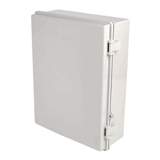
NEMA-4 Plastic Wi-Fi Access
Point Enclosure
Model: EN1511N4LATCH
Español 7 • Français 13 • Русский 19
WARRANTY REGISTRATION
Register your product today and be
automatically entered to win an ISOBAR
surge protector in our monthly drawing!
www.tripplite.com/warranty
1111 W. 35th Street, Chicago, IL 60609 USA • www.tripplite.com/support
Copyright © 2019 Tripp Lite. All rights reserved.
1
Advertisement
Table of Contents

Related Manuals for Tripp Lite EN1511N4LATCH


Summary of Contents for Tripp Lite EN1511N4LATCH
- Page 1 Español 7 • Français 13 • Русский 19 WARRANTY REGISTRATION Register your product today and be automatically entered to win an ISOBAR surge protector in our monthly drawing! www.tripplite.com/warranty 1111 W. 35th Street, Chicago, IL 60609 USA • www.tripplite.com/support Copyright © 2019 Tripp Lite. All rights reserved.
-
Page 2: Components List
Components List IMPORTANT: Ensure you have received all parts according to the component checklist prior to installing. If any parts are missing or faulty, visit www.tripplite.com/support for service. Installation 1. Attach Mounting Feet to the Rear of the Enclosure... - Page 3 Installation 2. Mount Enclosure to Wall Find a wood stud location for mounting the enclosure Mark the exact location of the mounting holes Drill pilot holes Attach the enclosure onto the wall (Mounting Hardware Not Included) • Installers are responsible for providing wall-mounting hardware. Use a minimum of two #10 x 2” or larger screws (not included) to secure the enclosure in place.
- Page 4 Installation 3. Use a Drill to Create a Rear or 4. Run Data and Power Cable (If Side Conduit Cutout Required) Through the Conduit Cutout Note: To maintain a NEMA rating, use sealed fittings in the cutouts when connecting to conduit.
- Page 5 Installation 5. Using the Provided Screws, Attach the Access Point IMPORTANT: Attach all data and power cables to the access point prior to attaching to the enclosure. 5a. Cisco Universal Bracket 5b. Aruba or Other T-Bar Mounted (AIR-AP-BRACKET-2)* Access Point Installation Installation * Cisco brackets not included.
-
Page 6: Warranty And Product Registration
PRODUCT REGISTRATION Visit www.tripplite.com/warranty today to register your new Tripp Lite product. You’ll be automatically entered into a drawing for a chance to win a FREE Tripp Lite product!* * No purchase necessary. Void where prohibited. Some restrictions apply. See website for details. -
Page 7: Guía De Instalación
Guía de Instalación Gabinete de Plástico NEMA-4 para Punto de Acceso Wi-Fi Modelo: EN1511N4LATCH English 1 • Français 13 • Русский 19 1111 W. 35th Street, Chicago, IL 60609, EE. UU. • www.tripplite.com/support Copyright © 2019 Tripp Lite. Todos los derechos reservados. -
Page 8: Lista De Componentes
Lista de Componentes IMPORTANTE: Antes de proceder a instalar, asegúrese de haber recibido todas las piezas de acuerdo con la lista de comprobación de componentes. Si faltase cualquier parte o estuviese dañada, visite www.tripplite.com/support para solicitar servicio. Instalación 1. Acople Patas de Instalación a la Parte Posterior del Gabinete... - Page 9 Instalación 2. Instalación del Gabinete a la Pared Localice un punto en el travesaño de madera para la instalación del gabinete Marque la posición exacta de los orificios de instalación Barrene los orificios piloto Coloque el gabinete sobre la pared (No Incluye Accesorios de Instalación)
- Page 10 Instalación 3. Utilice un Taladro para Hacer 4. Conduzca el Cable de Datos y un Recorte para Conducto Alimentación (Si se Requiere) Posterior o Lateral A Través del Recorte para el Conducto Nota: Para mantener una especificación NEMA, utilice accesorios sellados en los recortes al conectar a conductos.
- Page 11 Instalación 5. Con los Tornillos Suministrados, Coloque el Punto de Acceso IMPORTANTE: Coloque todos los cables de datos y alimentación al punto de acceso antes de colocarlo en el gabinete. 5a. Instalación de Soporte de 5b. Instalación de Punto de Acceso Universal para Cisco en Barra Aruba u Otra Barra en T (AIR-AP-BRACKET-2)*...
- Page 12 Ya que las aplicaciones individuales están sujetas a gran variación, el fabricante no garantiza la adecuación de estos dispositivos para alguna aplicación específica. Tripp Lite tiene una política de mejora continua. Las especificaciones están sujetas a cambio sin previo aviso. Las fotografías e ilustraciones pueden diferir ligeramente de los productos reales.
-
Page 13: Guide D'installation
Guide d'installation Boîtier de point d'accès Wi-Fi en plastique NEMA-4 Modèle : EN1511N4LATCH English 1 • Español 7 • Русский 19 1111 W. 35th Street, Chicago, IL 60609 USA • www.tripplite.com/support Droits d'auteur © 2019 Tripp Lite. Tous droits réservés. -
Page 14: Liste Des Composants
Liste des composants IMPORTANT : S'assurer d'avoir reçu toutes les pièces conformément à la liste de vérification des composants avant de procéder à l'installation. Si des pièces sont manquantes ou défectueuses, visiter www.tripplite.com/support pour obtenir de l'aide. Installation 1. Fixer les pieds de montage à l'arrière du boîtier. - Page 15 Installation 2. Montage du boîtier au mur Trouver l'emplacement des montants muraux en bois pour monter le boîtier. Marquer l’emplacement exact des trous de montage. Percer des avant-trous. Fixer le boîtier au mur. (quincaillerie de montage non incluse) • Les installateurs sont responsables de fournir la quincaillerie pour le montage au mur. Utiliser au moins deux vis n° 10 x 2 po ou de plus grande taille (non incluses) pour retenir le boîtier en place.
- Page 16 Installation 3. Utiliser une perceuse pour 4. Acheminer le câble d'alimentation créer une découpe de conduite et de données (le cas échéant) arrière ou latérale. dans la découpe de la conduite. Remarque : Pour garder une capacité nominale NEMA, utiliser des raccords étanches dans les découpes au moment de connecter à...
- Page 17 Installation 5. En utilisant les vis fournies, fixer le point d'accès. IMPORTANT : Fixer tous les câbles d'alimentation et de données au point d'accès avant de le fixer au boîtier. 5a. Installation du support 5b. Installation de points d'accès universel Cisco Aruba ou monté...
-
Page 18: Garantie
à l'aptitude ou l'adaptation de ces dispositifs pour une application spécifique. La politique de Tripp Lite en est une d’amélioration continue. Les spécifications sont sujettes à changement sans préavis. Les produits réels peuvent différer légèrement des photos et des illustrations. -
Page 19: Руководство По Установке
Корпус пластмассовый для точек доступа к сети Wi-Fi (степень защиты NEMA-4) Модель: EN1511N4LATCH English 1 • Español 7 • Français 13 1111 W. 35th Street, Chicago, IL 60609 USA • www.tripplite.com/support Охраняется авторским правом © 2019 Tripp Lite. Перепечатка запрещается. - Page 20 Перечень комплектации ВНИМАНИЕ! Перед началом установки убедитесь в наличии всех деталей согласно перечню комплектации. В случае отсутствия или повреждения каких- либо деталей обратитесь за помощью на страницу www.tripplite.com/support. 4 шт. 4 шт. 1 шт. 2 шт. 2 шт. 4 шт. 1 шт.
- Page 21 Установка 2. Крепление корпуса к стене Определите местоположение элементов деревянного каркаса для крепления корпуса Разметьте точное местоположение монтажных отверстий Высверлите направляющие отверстия Прикрепите корпус к стене (Монтажные приспособления в комплект поставки не входят) • Ответственность за обеспечение оснастки для настенного крепления возлагается на установщика. Для крепления корпуса используйте два винта #10 x 2” или большего...
- Page 22 Установка 3. Высверлите отверстие с тыльной или 4. Проложите интерфейсный и питающий боковой стороны для подвода кабелей кабели (при необходимости) через высверленное отверстие Примечание. Для сохранения уровня защиты NEMA следует устанавливать в высверленные отверстия муфты с уплотнителями при соединении с кабель-каналом.
- Page 23 Установка 5. Прикрепите точку доступа с помощью винтов из комплекта ВНИМАНИЕ! Все интерфейсные и питающие кабели должны подсоединяться к точке доступа до крепления корпуса. 5a. Установка с универсальным 5b. Установка точки доступа Aruba или другого кронштейном Cisco аналогичного устройства, прикрепляемого к (AIR-AP-BRACKET-2)* Т-образному...
- Page 24 данных изделий для какого-либо конкретного применения или их соответствия каким-либо конкретным требованиям. Компания Tripp Lite постоянно совершенствует свою продукцию. В связи с этим возможно изменение технических характеристик без предварительного уведомления. Внешний вид реальных изделий может несколько отличаться от представленного на фотографиях и иллюстрациях.