Table of Contents
Advertisement
Quick Links
Enabling Australia's Field Technicians to build, troubleshoot
and maintain better communications networks.
This reference material is provided by TMG Test Equipment,
VIAVI's only Master Distributor for Contractors in Australia
Industry Best Pricing
Short to Medium Project-Based Rental Solutions
Dedicated Technical & After-Sales Support
In-house Diagnostics, Repair & NATA Calibration Laboratory
FREECALL
Finance Available
1800 680 680
Advertisement
Table of Contents
Troubleshooting

Summary of Contents for JDS Uniphase 2000 Platform
- Page 1 Enabling Australia’s Field Technicians to build, troubleshoot and maintain better communications networks. This reference material is provided by TMG Test Equipment, VIAVI’s only Master Distributor for Contractors in Australia Industry Best Pricing Finance Available Short to Medium Project-Based Rental Solutions Dedicated Technical &...
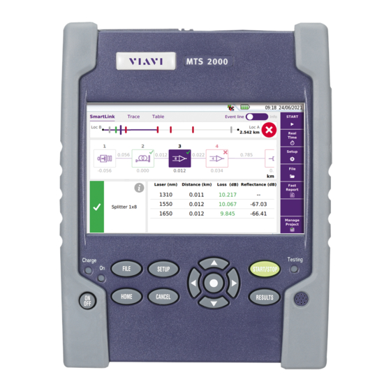
- Page 2 JDSU 2000 Platform Handheld, modular Platform designed for the construction, turn-up and maintenance of fiber networks User Manual...
- Page 4 JDSU 2000 Platform Handheld, modular Platform designed for the construction, turn-up and maintenance of FTTx networks User Manual...
- Page 6 Notice Every effort was made to ensure that the information in this document was accurate at the time of printing. However, information is subject to change without notice, and JDSU reserves the right to provide an addendum to this document with information not available at the time that this document was created.
- Page 7 It is the responsibility of the equipment owner to return the equipment to JDSU for appropriate disposal. If the equipment was imported by a reseller whose name or logo is marked on the equipment, then the owner should return the equipment directly to the reseller. Instructions for returning waste equipment to JDSU can be found in the Environmental section of JDSU’s web site at www.jdsu.com.
-
Page 8: Table Of Contents
......2 About the 2000 Platform ........3... - Page 9 ..23 Defining the screen parameters of the 2000 Platform ........23 Backlight .
- Page 10 Table of Contents ....28 Display of results and commands ....28 Result of the measurement in progress .
- Page 11 ........59 Storage media ... . .60 Storage media built into the 2000 Platform User Manual 790000002/00...
- Page 12 ... . .64 Connecting the 2000 Platform and the PC ..... .64 Configuring the 2000 Platform .
- Page 13 . . .94 Formating the USB memory stick onto the 2000 Platform ........94 Erase disk .
- Page 14 Table of Contents ....97 General information on warranty ......97 Hardware Warranty .
- Page 15 Table of Contents User Manual 790000002/00...
- Page 16 About This Guide The 2000 Platform of JDSU provides a handhled modular platform designed for the construction, turn-up and maintenance of fiber networks. The topics discussed in this chapter are as follows: – “Purpose and scope” on page xvi –...
-
Page 17: Purpose And Scope
Assumptions This guide is intended for novice, intermediate, and experienced users who want to use the 2000 Platform effectively and efficiently. We are assuming that you have basic computer and mouse/track ball experience and are familiar with basic telecommunication concepts and terminology. -
Page 18: Conventions
About This Guide Conventions During off-hours, you can request assistance by doing one of the following: – leave a voice mail message at the Technical Assistance number in your region – e-mail North American Technical Assistance Center, tac@jdsu.com, or European Technical Assistance Center, support.uk@jdsu.com –... - Page 19 About This Guide Conventions Table 3 Keyboard and menu conventions Description Example A plus sign + indicates simulta- Press Ctrl+s neous keystrokes. A comma indicates consecutive Press Alt+f,s key strokes. A slanted bracket indicates On the menu bar, click choosing a submenu from Start >...
-
Page 20: 2000 Platform Overview
2000 Platform Overview Chapter 1 This chapter provides a general description of the 2000 Platform. Topics discussed in this chapter include the following: – “Unpacking the instrument” on page 2 – “About the 2000 Platform” on page 2 – “Main features” on page 3 –... -
Page 21: Unpacking The Instrument
A shoulder strap About the 2000 Platform The architecture of the 2000 Platform is made of one Platform, to which a module can be added to perform tests on fiber networks. The modules that can be fitted to the 2000 Platform are interchangebale in the field and different kinds of module are usable: –... -
Page 22: Main Features
RJ45 plug for Ethernet interface – Two USB 2.0 host connectors for Microscope, USB memory stick, mouse, keyboard, ... – One mini USB 2.0 device connector to connect the 2000 Platform to a PC – An audio jack to connect a headset –... - Page 23 Chapter 1 2000 Platform Overview Main features Fig. 1 2000 Platform with module TFT 5’’ Color Touchscreen Indicators Loudspeaker Hardkeys Fig. 2 2000 Platform: Front view RJ45 USB host Power Meter VFL Mini USB AC/DC Headset jack device Input Fig. 3...
-
Page 24: Hard Keys And Indicators
Chapter 1 2000 Platform Overview Hard keys and Indicators Hard keys and Indicators Front panel hard keys Fig. 4 Hard keys and Indicators Table 2 Hard keys description Hardk Function Main on/off switch This button calls up the file explorer. It allows to: –... -
Page 25: Front Panel Indicators
Front panel The 2000 Platform is equipped with three indicators, lit into a different color acccording to the status of the unit. indicators Table 3... -
Page 26: Power Supply
Chapter 1 2000 Platform Overview Power Supply Power Supply The 2000 Platform may operate with – the Li-Polymer battery, already set into the equipment on delivery. – an AC adapter/charger, via a power cable on which has been set the correct country adaptable plug. - Page 27 Chapter 1 2000 Platform Overview Power Supply User Manual 790000002/00...
-
Page 28: Safety Information
Safety information Chapter 2 This chapter gives the main information on the safety conditions when using the 2000 Platform: – “Battery and AC/DC safety information” on page 10 – “Precautions relating to optical connections” on page 10 – “Laser Safety instructions” on page 11... -
Page 29: Battery And Ac/Dc Safety Information
If another adapter or battery is used, it may damage the 2000 Platform itself. Using the 2000 Platform with a battery other than the one supplied by the manufacturer of the 2000 Platform may entail risks of fire or explosion. -
Page 30: Laser Safety Instructions
The optical connectors must therefore be clean and dust-free. If the optical connection is not being used, protect the connections of 2000 Platform using the protective caps. Laser Safety instructions The provisions contained in two standards define the safety procedures... - Page 31 Chapter 2 Safety information Laser Safety instructions User Manual 790000002/00...
-
Page 32: Starting Up
“Setting the adaptable plug to the mains adapter” on page 15 – “Charging the battery” on page 16 – “Switching the 2000 Platform on and off” on page 17 – “First start: configuring your regional settings” on page 18 User Manual... -
Page 33: Fitting And Removing A Module
Chapter 3 Starting up Fitting and removing a module Fitting and removing a module The 2000 Platform must be switched off, and if it is operating on the mains, its supply cable must be unplugged. Fitting a Turn the instrument face down on the work surface. -
Page 34: Setting The Adaptable Plug To The Mains Adapter
Setting the adaptable plug to the mains adapter Setting the adaptable plug to the mains adapter The 2000 Platform is supplied as standard with a mains adapter and 5 country adaptable plugs (Europe / UK / US / Australia/Japan). To set the correct plug to the mains adapter: Make flush the connector onto the mains adapter with the adaptable plug slots. -
Page 35: Charging The Battery
(see page 15). mains adapter At the right side of the 2000 Platform, lift up the power supply socket protector and plug in the mains adapter. Connect the adapter to the mains. indicator lamp starts to blink in green. -
Page 36: Battery Charging Time
Chapter 3 Starting up Switching the 2000 Platform on and off Battery If the battery is completely discharged, the time taken to recharge is: charging time – approximately 3.5 hours, if the apparatus is not in use (Charge indi- cator solid red) –... -
Page 37: Switching Off The 2000 Platform
Next time the key is pressed, they are recalled. Resetting the If the 2000 Platform freezes, prolonged pressure (about 4 s.) on the key will reset the instrument. 2000 Platform First start: configuring your regional settings Once the 2000 Platform is switched on, the first screen displayed allows to configure the regional settings. - Page 38 Chapter 3 Starting up First start: configuring your regional settings Fig. 8 Regional Settings Click on Language and select the language to be used for the equipment. Click on Date and enter the current date, using the numeric keypad displayed using the menu key Edit Number. Click on Time and enter the current time, using the numeric keypad displayed using the menu key Edit Number.
- Page 39 Chapter 3 Starting up First start: configuring your regional settings User Manual 790000002/00...
-
Page 40: Configuring The 2000 Platform
The topics discussed in this chapter are as follows: – “Displaying the System Settings screen” on page 22 – “Defining the screen parameters of the 2000 Platform” on page 23 – “Defining the Audio parameters of the 2000 Platform” on page 24 –... -
Page 41: Displaying The System Settings Screen
Chapter 4 Configuring the 2000 Platform Displaying the System Settings screen Displaying the System Settings screen To display the System Settings screen, you must: Press the H hard key to reach the Home page. Fig. 9 Home page Activate the Settings icon to open the System Settings screen. -
Page 42: Defining The Screen Parameters Of The 2000 Platform
Screen Saver Click on Screen Save if you wish to activate a screen saver to the equip- ment, to extend the life of the battery, in case the 2000 Platform is not used for some time. Instead of the normal screen, a small animated picture of the 2000 Plat- form is displayed on the blackened screen. -
Page 43: Defining The Audio Parameters Of The 2000 Platform
Choose a time after which the 2000 Platform will be switched off automatically, if no action has been done for that period: 5, 10 or 30 minutes. Select if the 2000 Platform must not be switched off, even if there is inactivity on the equipment. User Manual 790000002/00... - Page 44 Power meter, VFL (Visual Chapter 5 Fault Locator) & Talkset A variety of built-in optical options are available when ordering. See references in Chapter 10 “Options and accessories”, for details. The topics discussed in this chapter are as follows: – “Connection to the power meter, VFL and Talkset”...
-
Page 45: Connection To The Power Meter, Vfl And Talkset
To do this, use the «Reference Value» function. Using the Power meter The power meter function is an option chosen at the time of order and incorporated into the 2000 Platform in the factory. To activate the function: Press the button... - Page 46 Chapter 5 Power meter, VFL (Visual Fault Locator) & Talkset Using the Power meter Fig. 13 Configuration of power measurement Wavelength Selecting wavelength: - Auto: the wavelength of the input signal will be automatically detected and selected to perform the measurement: 850, 980, 1300, 1310, 1420, 1450, 1480, 1490, 1510, 1550 or 1625 nm: measurement performed at specified wavelength.
-
Page 47: Display Of Results And Commands
Chapter 5 Power meter, VFL (Visual Fault Locator) & Talkset Using the Power meter wavelength, then press > to access choice of value. NOTE To copy a Reference Level or a Attenuator Compensator on all wave- lengths, select the reference wavelength and click on Update for All Wavel.. -
Page 48: Commands Of The Power Meter Parameters
Chapter 5 Power meter, VFL (Visual Fault Locator) & Talkset Using the Power meter direction key . The table shows the power measured in dBm, the rela- tive power (in dB) and the reference level in dBm (if units = dB), together with the mode. -
Page 49: Performing A Measurement
Chapter 5 Power meter, VFL (Visual Fault Locator) & Talkset Using the Power meter Standard Reference Selects the current result as reference value to measure the attenuation of a link. This reference is displayed under the measurement result until a new reference value is chosen. -
Page 50: Vfl Function
Chapter 5 Power meter, VFL (Visual Fault Locator) & Talkset VFL Function In the Results page, press the Powermeter Config. > Zero soft key and validate. Carrying out the reference measurement Fix the adapter corresponding to the jumper to the optical connector of the power meter. -
Page 51: Storing And Reloading Results
Store trace. Two files are being saved : – The first file is used with the 2000 Platform and allows to retrieve all measurement results. It is saved with the extension «.Lts». – The second file is a ASCII file using tabulations to separate values. -
Page 52: Talkset Function
Each end of the optical link must be provided with a 2000 Platform equipped with the Talkset option. NOTE It is possible to use the talkset of the 2000 Platform and to carry out measurements at the same time, on a different fiber. Talkset... -
Page 53: Adjusting Volume Level
Adjusting The sound is transmitted to the earphones of the headset and, if this function has been activated, to the speaker in the 2000 Platform base. To volume level activate the base loudspeaker and adjust the volume: Press the key. -
Page 54: Scope
Scope Chapter 6 The scope function is a hot-plug feature enabled directly when inserting a JDSU scope supplied as an accessory (see "References of accesso- ries" page 76). The topics discussed in this chapter are as follows: – "Scope feature" page 36 –... -
Page 55: Scope Feature
Squeeze both ends to release Fig. 16 P5000 Probe components Installation of tips The Pass/Fail analysis function on the 2000 Platform can only be used with certain inspection tips mounted on the P5000. Pass / Fail results Standard patch cord tips... -
Page 56: Configuring The P5000 Scope
Chapter 6 Scope Configuring the P5000 Scope Configuring the P5000 Scope Scope Plug in your JDSU scope into a USB port from the 2000 Platform. connection Push the button Validate the Scope function Connect probe with the fiber being inspected. -
Page 57: Report
Chapter 6 Scope Configuring the P5000 Scope Report The parameters in Report box allow to configure the Report page setup. On the line Company, enter the name of your company using the edition keypad. On the line Logo, you can select an image on the 2000 Explorer once clicking on the right arrow key, which will be displayed on the upper left part of the report. -
Page 58: Starting Up With The Scope
Chapter 6 Scope Starting up with the scope Starting up with the scope Once the FiberScope icon is validated: Press R hard key ESULTS Fig. 19 Example of the result using the P5000 scope Luminosity and Luminosity and contrast may be set manually by using the Bright/Cont . -
Page 59: Freeze Mode
Chapter 6 Scope Launching a test of the connector and fiber end-face Freeze mode Once the image is acceptable (sharpness, luminosity and contrast are tuned correctly), you may freeze the picture. This feature allows to store in memory the resulting picture. Freezing a scope result does not store the picture in a file (see "File menu"... - Page 60 Chapter 6 Scope Launching a test of the connector and fiber end-face The test is completed: – once the Led Testing is no more lit in red – once the icon is no more displayed on the upper banner – once a screen as the following one displays: NOTE To configure the Pass/Fail critera, refer to...
-
Page 61: Mosaic Mode
Chapter 6 Scope Launching a test of the connector and fiber end-face Mosaic Mode It is possible to display only one picture in full screen (640 * 390 pixels) or up to four pictures (320*180 pixels each, including the live camera picture) in mosaic mode. -
Page 62: Loading A Picture
Click on Load >Confirm Load Recognized pictures are images resulting from the Scope option and saved on disk via the 2000 Platform. Some pictures resulting from the Scope option may appear nevertheless unrecognized, if they have been stored with a different Scope application, or if the JPG file has been opened and modified under another JPG editor. - Page 63 Chapter 6 Scope File menu The report generation is completed once the icon is no more displayed on the upper banner. NOTE The pdf report will be saved on the disk, in the directory Scope. Display of the report Once the report has been generated: Return to the page, and select the File Explorer Select the pdf file of the report in the directory Scope.
-
Page 64: File Management
File management Chapter 7 The files management with the 2000 Platform can be performed, wether a module is set onto the 2000 Platform or not. The topics discussed in this chapter are as follows: – “File Explorer Overview” on page 46 –... -
Page 65: File Explorer Overview
Chapter 7 File management File Explorer Overview File Explorer Overview To reach the File Explorer page – On the Home page, select the File Explorer icon. The File Explorer page appears. Fig. 23 File Explorer page Directories and Files selections Directory To select a directory from the explorer page: selection... -
Page 66: Files Selection
Chapter 7 File management Directories & Files editing functions Files selection To select one or several files from the explorer page: Press on files that must be selected. To select a list of files using the keys of the Platform: Select and validate the first file of the list (underlined in red) Set the cursor on the last file of the list (underlined in blue) Maintain the right direction key... -
Page 67: Renaming A Directory / File
Chapter 7 File management Working with directories and files from the explorer Press Cut to delete the directory / file(s) from their initial location On the left of the screen, select the directory; or select the new storage media. Click on Paste menu key. Renaming a Select the directory / file to be renamed (see “Directories and Files... -
Page 68: Opening Files
If different types of files have been selected in the Explorer, only the last one selected will open. File Types For files recognized by the 2000 Platform, the types are symbolized by icons. E.g. Icon Type of FO file OTDR file (.SOR extension) -
Page 69: Sorting Files
JPEG / JPG file (.JPEG extension) PNG file (.PNG extension) XML file (.XML extension) With the 2000 Platform, you can open and load any kind of FO files (OTDR, OSA, PON, LTS) even if the corresponding module is not set into the Platform. - Page 70 Fig. 27 Direct connection 2000 Platform <-> PC Once connection is established, confirm that you wish to activate the USB link in the pop-up window on the 2000 Platform. Fig. 28 Confirmation of files export via USB cable A message displays on the bottom right side of the PC informing a new hardware is detected.
-
Page 71: Transferring Files Onto The Pc
Fig. 29 Open 2000 disk content The 2000 platform disk content opens onto the PC. Transferring files Select the file(s) from the 2000 Platform to be transferred onto the onto the PC Fig. 30 Files selection from the 2000 Platform Press Ctrl + C, or right click and select Copy. -
Page 72: Sending Files By Bluetooth
If the desired device is not displayed on the screen, or if no devices are detected, press the Search Devices soft key. The 2000 Platform is searching for the devices which could be used via Bluetooth with the equipment. REMINDER You may need to activate bluetooth on the other device to allow pairing. -
Page 73: Transfering Files Via Bluetooth
Push the Pair key to connect the device to the Platform If prompted, enter a pairing code. The code must be identical on the 2000 Platform and the device. Once the bluetooth device and the Platform are paired, a screen is displayed with the description of the device Fig. -
Page 74: Removing The Pairing
I/O Interfaces, select Disable on the Bluetooth line. Creating a screenshot You can create captures of what is displayed on the screen, directly from the 2000 Platform. Configuring the To configure the screenshot and choose the format of the generated file:... -
Page 75: Name Of The Screenshots Files
Fig. 34 Example of screenshot, open in the Web Browser of the 2000 Platform The file is saved in the directory Print, on the storage media disk. Creating a report Once the results page of a function is opened (example: OTDR trace, Power Meter results...), it can be exported in a report, using the 2000... -
Page 76: Creating The Report
Chapter 7 File management Creating a report Select Settings icon to reach the System Settings page. In the Report box, on the line Mode, select Report. Choosing this option, you can save the open file in a JPG, PNG or PDF file report, exactly as if the file was printed on paper. -
Page 77: Name Of The Report
Chapter 7 File management Merging pdf or txt files Click on the upper banner of the screen and, in the virtual control buttons bar, press Export key The icon displays until the end of process. Press the key to find the JPG, PNG or PDF file in the Explorer The files are saved in the directory Print, on the disk media storage. -
Page 78: Storage Media
“Renaming a directory / file” on page 48). Storage media For saving or recalling data, the 2000 Platform offers a wide choice of media, both built-in and external. Free space on selected media is clearly displayed at the bottom of the left panel. -
Page 79: Storage Media Built Into The 2000 Platform
2000 Platform External USB The 2000 Platform is equipped with 2 USB ports as standard. One of these can be used to connect an external storage medium, in particular storage media a USB memory stick. -
Page 80: Abbreviations For Storage Media
Chapter 7 File management Storage media Chapter 11 “Maintenance and Troubleshooting” if any problem occurs with the USB memory stick Abbreviations The abbreviations used in the explorer for the different storage media are: for storage media Abbreviation Storage medium disk Internal flash memory usbflash USB memory stick... - Page 81 Chapter 7 File management Storage media User Manual 790000002/00...
-
Page 82: Transferring The 2000 Platform Interface
Transferring the 2000 Chapter 8 Platform Interface The 2000 Platform can be used in combination with a PC in order to transfer the Platform Interface onto a PC, or to access the internal memory or USB memory stick contents on the PC. -
Page 83: Establishing Connection
Chapter 8 Transferring the 2000 Platform Interface Establishing connection Establishing connection The connection between 2000 Platform and the PC can be done directly, or via a local network. The transfer of the interface can be done using a VNC window on PC. - Page 84 Note the IP Address displayed in the System Settings page. Wait about 10 seconds the connection is established. The 2000 Platform Interface can now be transferred onto the PC, or the internal memory or USB key ocntents can be transferred on PC..
-
Page 85: Transferring The Interface
Click to install TightVNC software on your PC (not mandatory) Fig. 40 VNC window You can use keyboard mouse of the PC to control the 2000 Platform (see “Equivalence between the keyboard and 2000 Platform” on page 67). NOTE Once Remote screen is accessbile via VNC, the icon... -
Page 86: Virtual Control Buttons Bar
The virtual control buttons bar is displayed during a few seconds. You may click on any of these buttons to obtain exactly the same results than using the hard keys on the front panel of the 2000 Platform. Equivalence between the keyboard and 2000 Platform... - Page 87 Function on the 2000 Platform External keyboard Quit without saving (Abort) Escape/Echap. a. The Export function is available directly on the 2000 Platform pushing simultaneously the left and right arrow keys. NOTE Those equivalences are also valid with a keyboard directly connected to the 2000 Platform via one USB port.
-
Page 88: Technical Specifications
Technical specifications Chapter 9 This chapter contains the technical specifications of the 2000 Platform mainframe. The topics discussed in this chapter are as follows: – “Display specifications” on page 70 – “Memory” on page 70 – “Input/Output” on page 70 –... -
Page 89: Display Specifications
The instrument can be supplied with one Li-Polymer battery. Endurance of the 2000 Platform with battery Measurement conditions: – at +25 °C, – at full battery capacity (4.5 Ah), – 2000 Platform equipped with one OTDR LM module User Manual 790000002/00... -
Page 90: Mains Adapters
Supply or Power assigned in AC and in DC: 25 W Dimensions - Weight Weight 2000 Platform without options, battery nor module 692 g 1.52 lbs 2000 Platform with a Li-Polymer battery and one 1.21 kg 2.67 lbs OTDR LM Module Li-Polymer battery 172 g 0.37 lbs... -
Page 91: Environment
6 impacts dropped from a height of 1m on a pinwood floor of 5 cm thickness (1 impact on each of its 6 sides, with power off). Shocks The 2000 Platform resists the following test: – 3 shocks per axis along each of the 3 axes, with power off. -
Page 92: Vibration
– 3g acceleration test for the range 16 Hz to 200 Hz. Flammability The 2000 Platform housing (in ABS, type V0) does not propagate fire. Characteristics of the options Power meter Specifications given for 25°C, after 20 minutes stabilization time and after zero setting. - Page 93 Chapter 9 Technical specifications Characteristics of the options User Manual 790000002/00...
-
Page 94: Options And Accessories
This chapter shows the references of the options and accessories of the 2000 Platform. The topics discussed in this chapter are as follows: – “References of options for the 2000 Platform” on page 76 – “References of accessories” on page 76 –... -
Page 95: References Of Options For The 2000 Platform
ETB2000T Power Meter / VFL / Wifi / Bluetooth options Reference Optical Power Meter option for T-BERD/MTS-2000 Platform E20PM Power Meter and VFL option for T-BERD/MTS-2000 Platform E20PMVFL Power Meter and Talkset option for T-BERD/MTS-2000 Platform E20TSPM Mains options Reference... -
Page 96: References Of Manuals
Chapter 10 Options and accessories References of manuals References of manuals User manual for 2000 Platform Reference Printed User manual for 2000 Platform (French) E2000M01 Printed User manual for 2000 Platform (English) E2000M02 Printed User manual for 2000 Platform (German) - Page 97 Chapter 10 Options and accessories References of result processing software User Manual 790000002/00...
-
Page 98: Maintenance And Troubleshooting
Maintenance and Chapter 11 Troubleshooting This chapter describes how to maintain your unit and identify and correct problems related to the 2000 Platform. The topics discussed in this chapter are as follows: – “Maintenance procedure” on page 80 – “Recycling Information” on page 92 –... -
Page 99: Cleaning
Centre, which will undertake the appropriate troubleshooting and repair work. The performance and technical complexity of the 2000 Platform class this instrument in a new generation of equipment, for which JDSU has laid down a maintenance policy based on the principle of standard module replacement. -
Page 100: Cleaning The Optical Cable Connector
NOTE If your module has a universal connector, unscrew its adaptor to access the ferule. Accessing to On the 2000 Platform, some screens allows to display information on different elements of the equipment. the 2000 Platform To display the information on the 2000 Platform... -
Page 101: Software Options Page
The product contents: base, optical options, battery type, module installed and date of calibration for options concerned. The options set into the 2000 Platform are marked with a green tick. Software options This page allows to visualize the software options available on the 2000 Platform. -
Page 102: Accessing To The 2000 Platform Documentation
Chapter 11 Maintenance and Troubleshooting Maintenance procedure Fig. 44 Services Data page Accessing to All documents necessary for the 2000 Platform use are directly available onto the equipment. the 2000 Platform To display the list of documents available for 2000 Platform use: documentation Validate the Help icon on the Home page. -
Page 103: Installing A New Version Of The Software
Chapter 11 Maintenance and Troubleshooting Maintenance procedure Installing a new version of the software When a new software version is loaded, there is a risk of re-initializa- tion of the internal memory. Before installing the new software, it is therefore advisable to save the results in the memory, using the Save function called up by the button. - Page 104 Chapter 11 Maintenance and Troubleshooting Maintenance procedure Before installing the upgrade, you must format the USB memory stick (see “Formating the USB memory stick onto the 2000 Platform” on page 94). Once formated, disconnect the USB memory stick from the 2000 Platform using the key Eject USB in the Media Utilities page.
-
Page 105: Installation From Ethernet
Ethernet The update can be performed directly onto the equipment, using an http address. Connect the 2000 Platform to a PC via an Ethernet link. On the Home page, press Settings key to open the System Settings page. In I/O Interfaces, on the line Ethernet, select Mode: Dynamic. -
Page 106: Upgrading From The Boot
In this case, the upgrading starts automati- cally. Upgrading begins. The 2000 Platform is automatically rebooted. Upgrading takes several minutes. At the end, the 2000 Platform is automatically restarted. During the upgrade, the Testing indicator is lit in red. Do not push any button while the indicator is lit. -
Page 107: Install Option
The Testing indicator will be lit in red during upgrade. Do not push any key or remove the USB memory stick until the lit turns off. Once the upgrade is completed, the 2000 Platform will automatically tunrs on and display the Home page. Install Option This page allows to import the licence to get a software option. -
Page 108: Enter Manually The Licence
To import the license, you can either enter manually the licence code, given in the license file, (.lic file) or import this file with a USB memory stick connected to the 2000 Platform. It is strongly recommended to perform the installation using the importation of Licence via a USB memory stick. -
Page 109: Locking The 2000 Platform
In the page, click on Expert Tools Click on Instrument Lock Out Confirm the 2000 Platform locking by clicking on Confirm (or use the Cancel key to cancel the process). The numeric keypad is displayed Entrer the password to lock the instrument: 42000 with the numeric keypad displayed. - Page 110 Chapter 11 Maintenance and Troubleshooting Maintenance procedure Fig. 51 Password Click on Enter The 2000 Platform locking screen is displayed. Fig. 52 Locking screen Click on the Notepad Message key to add a message using the text edition. Unlocking the 2000 Platform Once the locking screen is displayed, click on the key Unlock Instrument.
-
Page 111: Returning An Instrument
Chapter 11 Maintenance and Troubleshooting Recycling Information Returning an When returning an instrument, it is essential to indicate the following minimum information: instrument – the type and serial number of the instrument (on the identification label) and the configuration code (under the bar code) –... - Page 112 Nothing happens on screen, - The Platform must be rebooted. whatever is the action done “Resetting the 2000 Platform” on page (menu key or hard key pressed...) You are using the 2000 Platform - Check the instrument is not configured to Auto off.
-
Page 113: Formating The Usb Memory Stick Onto The 2000 Platform
Formating the If the USB icon is displayed on the upper banner of the screen, when a USB memory stick is connected to the 2000 Platform, this may USB memory means the memory stick must be formatted. stick onto the... -
Page 114: Changing The Battery
Battery is not interchangeable in the field. It must be replaced exclusively for maintenance purpose. Accessing to the To access the battery of the 2000 Platform, proceed as follows: damaged battery Switch off the instrument and disconnect the mains supply. -
Page 115: Installing A New Battery
Date and Time parameters will be lost when battery is diconnected. Installing a new Set the battery into the Platform battery Connect the new battery in the connector of the 2000 Platform, in the right way using the location notch. Fig. 55 Setting a new battery User Manual... - Page 116 Chapter 11 Maintenance and Troubleshooting General information on warranty When putting a battery back into its seating, make sure that its connector engages correctly with the one of the base and that the door is correctly closed. Contact JDSU local Sales Service to get a new battery. Do not use any battery other than the one supplied with the instrument, or supplied by JDSU.
- Page 117 Chapter 11 Maintenance and Troubleshooting General information on warranty JDSU performed repairs shall be warranted from defective material and workmanship for a period of ninety (90) days, or until the end of the Initial Warranty Period, whichever is longer. Risk of loss or damage to Product returned to JDSU for repair or replacement shall be borne by customer until delivery to JDSU.
- Page 118 Index About page Environment Accessories Adapter specifications Attenuation File accuracy of measurement sending by bluetooth storage media transfer connection for process Battery charging time specifications Bluetooth Guarantee conditions pairing search devices specifications HTML file Cleaning optical connectors plates, housings and screen Indicators Connectors cleaning...
- Page 119 Index measurement reference reference measurement JPG,JPEG file results Jumper reference specifications zero value Power Meter file Processing software reference License enter manually import from USB License file Report result Memory capacity Module Scope fitting and removing adding a profile cladding MSOR file comment core...
- Page 120 Index Unpacking the instrument connection emission of light connection function disconnection specifications upgrade via User manual reference XML file User Manual 790000002/00...
- Page 121 Index User Manual 790000002/00...
- Page 123 Test and Measurement Regional Sales North America Latin America Asia Pacific EMEA www.jdsu.com Toll Free: 1 800 638 2049 Tel: +55 11 5503 3800 Tel: +852 2892 0990 Tel: +49 7121 86 2222 Tel: +1 240 404 2999 Fax:+55 11 5505 1598 Fax:+852 2892 0770 Fax:+49 7121 86 1222 Fax:+1 240 404 2195...