Table of Contents
Advertisement
Quick Links
Advertisement
Chapters
Table of Contents

Related Manuals for Sony MSU-750


Summary of Contents for Sony MSU-750
- Page 1 MASTER SETUP UNIT MSU-750 電気製品は、安全のための注意事項を守らないと、火災 警告 や人身事故になることがあります。 このオペレーションマニュアルには、 事故を防ぐための重要な注意事項と製 品の取り扱いかたを示してあります。 このオペレーションマニュアルをよく お読みのうえ、 製品を安全にお使いください。 お読みになったあとは、 いつ でも見られるところに必ず保管してください。 OPERATION MANUAL [Japanese/English] 1st Edition...
- Page 2 日本語 安全のために 電気製品は、 安全のための注意事項を守らないと、 火災や感電などにより死 警告表示の意味 亡や大けがなど人身事故につながることがあり、危険です。 オペレーションマニュアルおよ 事故を防ぐために次のことを必ずお守りください。 び製品では、次のような表示を しています。表示の内容をよく 安全のための注意事項を守る 理解してから本文をお読みくだ 2 ( J )〜3 ( J )ページの注意事項をよくお読みください。 さい。 警告 定期点検を実施する 長期間安全に使用していただくために、 定期点検を実施することをおすすめ この表示の注意事項を守らない します。 点検の内容や費用については、 ソニーのサービス担当者または営業 と、火災や感電などにより死亡 担当者にご相談ください。 や大けがなど人身事故につなが ることがあります。 故障したら使用を中止する 注意 ソニーのサービス担当者、または営業担当者にご連絡ください。 この表示の注意事項を守らない と、感電やその他の事故により 万一、異常が起きたら けがをしたり周辺の物品に損害 を与えたりすることがあります。 1 電源を切る。 異常な音、 におい、 2 電源コードや接続コードを抜く。 煙が出たら...
-
Page 3: Table Of Contents
メニューの構成と基本操作 ..................基本操作手順 ........................ 13(J) メニュー画面の基本構成 .................... 14(J) メニュー項目 ........................ 16(J) 23(J) 初期設定 ........................ 暗証番号の設定 ......................23(J) セキュリティステータスの設定 ................26(J) MSU-750の動作環境の設定 ..................27(J) 33(J) 仕様 ........................BVP-700/900 シリーズカメラシステムのマニュアル構成 メ ンテナンスマニュアルとシステムマニュアルには、 システムの BVP-700/900シリ ーズのカメ ラシステムでは、オペレーシ ョ ンマ 構築のしかた、 設置、 接続、 システムと して使用するために必要... - Page 4 下記の注意を守らないと、 警告 火災 感電 死亡 大けが や により や につながることがあります。 火災 感電 外装を外さない、改造しない 外装を外したり、改造したりすると、感電の原因となります。 内部の調整や設定および点検を行う必要がある場合は、 必ずサービストレー 分解禁止 ニングを受けた技術者にご依頼ください。 内部に水や異物を入れない 水や異物が入ると火災や感電の原因となります。 万一、 水や異物が入ったときは、 すぐに電源を切り、 電源コードや接続コー 禁止 ドを抜いて、 ソニーのサービス担当者または営業担当者にご相談ください。 指定の電源コードを使用する 指定以外の電源コードを使用すると、火災や感電の原因となります。 他の電源コードを使用する場合は、 ソニーのサービス担当者または営業担当 強制 者にご相談ください。 電源コードを傷つけない 電源コードを傷つけると、火災や感電の原因となります。 ・ 電源コードを加工したり、傷つけたりしない。 禁止 ・ 重いものをのせたり、引っ張ったりしない。 ・...
- Page 5 下記の注意を守らないと、 注意 けが 損害 をしたり周辺の物品に を与えることがあります。 カードスロットに異物を入れない 指定の IC カード以外のものを入れると、火災や感電の原因となることがあ ります。 禁止 安全アースを接続する 安全アースを接続しないと、 感電の原因となることがあります。 次の方法で アースを接続してください。 アース線を • 電源コンセントが 極の場合 接続せよ 指定の電源コードを使用することで安全アースが接続されます。 • 電源コンセントが 極の場合 指定の3極→2極の変換プラグを 変換プラグ 使用し、変換プラグから出てい る緑色のアース線を建物に備え られているアース端子に接続し てください。 アース線 安全アースを取り付けることができない場合は、 ソニーのサービス担当者ま たは営業担当者にご相談ください。 3 (J)
-
Page 6: 主な特長
概要 リモートコントロールパネルとの同時コントロールが可能 マス ターセッ ト アップユニッ トMSU-750は、 ソニーのBVPシ リ ーズの スタジオ/中継用CCDカラービデオカメ ラの調整機能を、 カメ ラコ 本機と リモー ト コン ト ロールパネル RCP-700シ リ ーズとの同時コン ト ン ト ロールユニッ ト(CCU)を介して リ モー ト コ ン ト ロールするためのコ ロールが可能です。 ン ト ロールパネルです。 HDTV システムの制御も可能... -
Page 7: 操作パネル
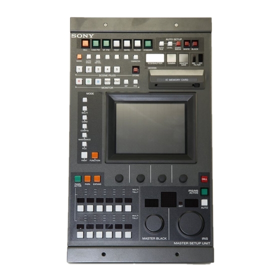
各部の名称と働き 操作パネル ボタン CAM PW ボタン VF PW ボタン テスト信号出力選択ボタン CLOSE ボタン STANDARD ボタン AUTO SETUP 部 AUTO SETUP AUTO LEVEL START/ WHITE BLACK CAM PW VF PW TEST BARS CLOSE STANDARD BREAK /CCU ON/OFF カメラ 機能 ボタン 表示部 5600K AUTO SKIN CHARACTER ECS/SHUTTER... - Page 8 各部の名称と働き VF PW ( ビューファインダー電源 ボタン AUTO SETUP ( オートセットアップ 部 押して点灯させる と、 ビデオカメ ラのビューフ ァイ ンダーに電源が供 カメ ラの自動調整を行います。 給されます。 も う1度押して消灯させる と、 ビューフ ァイ ンダーへの電源供給が遮 断されます。 AUTO SETUP AUTO LEVEL START/ 4 テスト信号出力選択ボタン WHITE BLACK BREAK 押して点灯させる と、 カメ ラのテス ト信号発生器が作動し、 対応す る信号が出力されます。...
- Page 9 8カメラ /CCU 機能 ON/OFF ボタン MONITOR( モニター出力選択 ボタン ビデオカメ ラやCCUの機能を、 本機からON/OFFする ことができ CCUのWF2 OUTPUT端子およびPIX2 OUTPUT端子からの出 ます。ボタ ン点灯時が ONになり ます。 力信号を切り換えます。 工場出荷時は、 4個のボタ ンにそれぞれ次のスイ ッチ機能が割り当 てられ、 3 個は空きになっています。 MONITOR 5600K AUTO SKIN CHARACTER KNEE DETAIL 1 出力信号選択ボタン WFボタ ン、 PIXボタ ンでCCUのOUTPUT 端子を選択した後、出 5600K: 5600K の電気色温度補正機能...
- Page 10 各部の名称と働き MULTI ( マルチモード インジケーター ンは点灯したままになり ますが、 Rおよび Gボタ ンは点滅を始めま す。 RとGを出力したいと きはぞれぞれのボタ ンを押します。点滅 それぞれ 1〜 12 のカメ ラのモー ドに応じて点灯します。 EXPAND が止ま り点灯します。 ボタ ン点灯時は、 13〜 24 のカメ ラのモー ドに応じて点灯します。 対応するカメ ラが、 マス ター/ス レーブモー ドでマス ターになってい qa カメラ選択部 る と緑に点灯し、 ス レーブになっている と きはオレンジ色に点灯しま す。...
- Page 11 qs 表示部 カード挿入部 ACCESS IC MEMORY CARD MASTER ECS/SHUTTER GAMMA GAIN FILTER ECS/SHUTTER(ECS 周波数 シャッタースピード 表示 ACCESS ( アクセス インジケーター 部 ICメモリ ーカー ドの状態を表示します。 現在選択されているECS周波数またはステップシャ ッ ターのス ピー 表示 意味 対応 ドを表示します。 消灯 カー ドが挿入されていません。 ECS モー ドとシャッターモー ドの切り換え、および ECS 周波数 / 緑色に点灯...
- Page 12 各部の名称と働き MAINTENANCE ( 3 カード取り出しボタン メンテナンス メ ンテナンスメニューを選択 します。 カー ドを取り出すとき押します。 CCUのH位相、 SC位相などの設定やカメ ラの各種メ ンテナン ご注意 スを行います。 ACCESSイ ンジケーターが赤く 点灯している とき (データの読み出 FILE ( ファイル フ ァイ ル操作メニューを選択します。 し/書き込み中)は、 カー ドを取り出さないでく ださい。 データが消え カメラや ICカー ド内のリ ファレンスファイル、 レンズファイル、 てしま う こ とがあ り ます。 シーンフ...
- Page 13 IRIS ( qj アイリス調整部 アイリス調整 つまみ AUTOボタ ン消灯時は、 レンズの絞り を手動調整します。 調整値は F ナンバーで表示部に表示されます。 AUTOボタン点 灯 時は、絞りの自動 調 整 の基 準 値を微 調 整 (±2F) します。 AUTO MASTER BLACK ( マスターブラック 調整部 つまみを回してマス ターブラ ッ ク を手動調整します。 調整値が表示 部に表示されます。 IRIS ql カメラナンバー タリー表示部...
-
Page 14: コネクターパネル
各部の名称と働き コネクターパネル POWER スイッチ AC IN 端子 -AC IN REMOTE POWER CCU/CNU CCU/CNU REMOTE 端子 AUX REMOTE 端子 POWER ( 電源 スイッチ 本機の電源を入 / 切します。 AC IN (AC 電源入力 端子 別売りの電源コー ドでAC電源に接続します。 別売りのプラグホル ダーで電源コー ドを本機に固定する こ とができます。 AUX REMOTE ( 補助リモート... -
Page 15: 基本操作手順
メニューの構成と基本操作 メニューが複数ページある場合は MSU-750 では、メニュー操作により、システム機器の調整など ペイ ン ト メニューやフ ァ ンク シ ョ ンメニューのよ う にメニューが複 様々な機能に対応します。 数ページある場合は、 vまたは Vを押して、必要に応じてメ ニューのページを切り換えます。 基本操作手順 ◆次ページ 「初期画面」参照。 サブメニューがある場合は ボタ ンを押して設定・調整画面を切り換えます。 ◆次ページ 「サブメニュー」 参照。 MODE 項目を設定・調整する。 Clear Home MULTI • 設定・調整項目 (パラメーター) に対応するつまみを回して CARD CONFIG (またはボタ... -
Page 16: メニュー画面の基本構成
メニューの構成と基本操作 メニュー画面の基本構成 初期画面 (ペイントメニュー) 押すと、メニューの ページ目 設定値をクリアすることができます。 Clear Home に戻ります。 調整画面参照 V Mod Skin Sat / Detail Detail Contrast いずれかを押して、メニュー この画面で調整可能な項目 項目群 Gamma のページを切り換えます。 Black White Flare の名称が表示されます。調整したい /Knee 項目 項目群 の部分を押すと、押し ページ番号 総ページ数 た部分が反転表示となり、パネルの (1/3 は、ぺイントメニューが全部 下半分が調整画面になります。 で ページあり、現在 ページ目が... - Page 17 ファンクションメニュー画面 Operation 選択時 この画面の設定は、 それぞれ対応する表示部(9(J)ページ)に表示 されます。 押すと、前に選択されていたメニュー Exit 画面に戻ります。 Operation 押して反転させると、この画面で [Ctrl]反転時に、希望のボタンを押して フィルターを選択できる状態になり Ctrl 反転させると、対応するフィルターが ます。 選択されます。[Ctrl]非反転時は、ビデ オカメラで選択されているフィルター Shutter に対応するボタンが反転します。 Master Gain Shutter Gamma 2000 30.0 0.45 それぞれ対応する位置の調整つまみで それぞれ対応する位置の調整つまみを回すか、v Vを押 調整できます。 して設定できます。vを押すたびに値が大きくなり、V を押すたびに小さくなります。押し続けると連続して 変わります。 選択時 押すと、前に選択されていたメ Exit ニュー画面に戻ります。 Operation それぞれ対応する機能を ON/OFF します。...
-
Page 18: メニュー項目
メニューの構成と基本操作 メニュー項目 操作/調整項目欄で●が付いている項目は調整つまみに割り当てられる項 目、それ以外の項目は、 メニュー画面上で操作する項目です。 マルチ制御メニュー MULTI ( ボタンで選択) メニュー 操作 調整項目 機能 Master/Slave Master マスター機の指定 Slave ス レーブ機の指定 All Slave すべてのカメ ラをス レーブ機に指定 All Off すべてのカメ ラのス レーブ指定を解除 Character Character on CNUキャ ラク ター出力 ON/OFF Default デフォル ト表示選択 System <#-#> コン ト ロールシステムの設定状態表示 Auto <#-#>... - Page 19 メンテナンスメニュー ( MAINTENANCE ボタンで選択) 次メニュー 次メニュー サブメニュー 操作 調整項目 機能 Adjusting Black Shading R/G/B H Saw/H Para/V Saw/V Para ブラ ッ クシェーディ ング調整 ● Auto B. Shading オー ト ブラ ッ クシェーディ ング調整 White Shading R/G/B H Saw/H Para/V Saw/V Para ホワイ ト シェーディ ング調整 ● White ホワイ トバラ ンス調整画面の選択 Auto W. Shading オー ト ホワイ ト シェーディ ング調整 Black Set Black Set R/G/B...
- Page 20 メニューの構成と基本操作 ファイル操作メニュー FILE ( ボタンで選択) メニュー サブメニュー 操作 調整項目 機能 Reference Ref Store リ フ ァ レンスフ ァイ ル登録 Ref Transfer CAM ->CARD リ フ ァ レンスフ ァイ ル転送 (カメ ラからICカー ド) CARD ->CAM リ フ ァ レンスフ ァイ ル転送 (ICカー ドからカメ ラ) CARD ->CAMs リ フ ァ レンスフ ァイ ル転送 ((ICカー ドから複数のカメ ラ) CAM ->CAMs リ...
- Page 21 ペイントメニュー PAINT ( ボタンで選択) ペイ ン ト メニューには1〜3があ り 、 メニュー画面上で切り換えます。 ペイントメニュー メニュー サブメニュー 操作 調整項目 機能 Black R/G/B/Master ブラ ッ クバラ ンス調整 ● オー ト ブラ ッ クバラ ンス調整 White R/G/B ホワイ トバラ ンス調整 ● オー ト ホワイ トバラ ンス調整 Flare R/G/B フ...
- Page 22 メニューの構成と基本操作 ペイントメニュー (続き) メニュー 操作 調整項目 機能 Skin Detail 1/2/3 (項目共通) Level スキンディ テールレベル調整 ● Phase スキンディ テール色相調整 ● Width スキンディ テール色相幅調整 ● Saturation スキンディ テールサチュ レーシ ョ ン調整 ● Auto Hue # スキンディ テールオー ト ヒュー調整 (チャ ンネル別) Gate # スキンディ テールゲー トON/OFF (チャ ンネル別) Skin Dtl # スキンディ...
- Page 23 ペイントメニュー メニュー サブメニュー 操作 調整項目 機能 Matrix Matrix 1 R–G/G–B/B–R マ ト リ ッ クス定数設定 ● Matrix 2 R–B/G–R/B–G マ ト リ ッ クス定数設定 ● Multi Phase マルチマ ト リ ックス領域選択 ● マルチマ ト リ ックス色相設定 ● Saturation マルチマ ト リ ックス彩度設定 ●...
- Page 24 メニューの構成と基本操作 ファンクションメニュー FUNCTION ( ボタンで選択) メニュー 操作 調整項目 機能 Operation Ctrl フ ィ ルター リ モー ト/ローカルモー ドの選択 ND (1/2/3/4/5) NDフ ィ ルターの選択 (Ctrl 反転時) CC (A/B/C/D/E) CCフ ィ ルターの選択(Ctrl 反転時) Shutter シャ ッ ターモー ドの ON/OFF ECS モー ドのON/OFF Shutter シャ...
-
Page 25: 暗証番号の設定
Adjusting めのエンジニアモー ドがあ り ます。 Date / Security Time エンジニアモー ドの使用を特定のオペレーターに限定する と きは、 あ らかじめ暗証番号を設定します。 設定後は、 暗証番号を入力す る こ とによって、 MSU-750をエンジニアモー ドに切り換える こ とがで きます。 [Security]を押す。 暗証番号の設定 セキュ リ ティ メニュー画面になり ます。 Security Menu Exit エンジニアモー ドを使用するための暗証番号は、 次のよ う に設定 ・... - Page 26 初期設定 暗証番号を入力し、 [OK]を押す。 テンキーを使用して任意の暗証番号(1〜8桁)を入力し、 [OK] を押す。 ご注意 入力した暗証番号は、画面上ではすべて*で表示されます。 ご注意 入力した暗証番号は、画面上ではすべて*で表示されます。 セキュ リ ティ メニュー項目が表示されます。 メ ッセージ 「Retype New Code No: (新しい暗証番号を再度 Security Menu Exit 入力してく ださい) 」 が表示されます。 Engineer Mode 確認のため、 手順5で入力した暗証番号を再度入力し、 [OK] Code Status Change を押す。 Engineer Mode セキュ リ ティ メニュー画面に戻り ます。 [Exit]を押す。...
- Page 27 モー ドでの設定が必要になった場合は、 次のよ う に暗証番号を解 ている[Code Enable]を押す (再度押して反転させれば、 設定 除する こ と もできます。 してある暗証番号がまた有効になり ます) 。 PARAボタ ン、 PANEL ACTIVEボタ ンおよびカメ ラ選択ボタ ン 手順 3 で [Code Delete]を押したときは、 メ ッセージ 「Code 1を押したまま、 MSU-750 の電源を入れる。 Delete, OK?」 が表示されるので、 [OK]を押してエンジニアプ ロテクシ ョ ン画面に戻る。 PARA ボタン [Exit]を押す。...
-
Page 28: セキュリティステータスの設定
初期設定 [Security]を押す。 セキュリティステータスの設定 セキュ リ ティ メニュー画面になり ます。 必要に応じて、 MSU-750のコ ン ト ロ−ル機能を制限する こ とができ ます。 Security Menu Exit この設定はエンジニアモー ドで行います。 操作 メニュー操作部 Engineer Mode コンフィギュレーションメニュー MODE Configuration Menu MULTI [Engineer Mode]を押して反転させる。 CARD Camera CONFIG テンキーと、暗証番号(Code No.)入力欄が表示されます。 MAINTENANCE FILE Engineer Mode... - Page 29 Engineer Mode 次の手順で操作します。 View Paint Full Lock Mode Only コンフィギュレーションメニュー ステータスを設定する。 MODE Configuration Menu [Ref. Enable] : MSU-750 でのリ フ ァ レンスフ ァイ ルの設定を許 MULTI 可する (工場出荷時: ON)。 CARD Camera [Lens Enable] : MSU-750 でのレンズフ ァイ ルの設定を許可す CONFIG MAINTENANCE る (工場出荷時: ON)。 FILE [OHB Enable] : MSU-750 での OHBフ ァイ ルの設定を許可す...
-
Page 30: Msu-750の動作環境の設定
初期設定 時計を合わせるには 時刻を合わせる。 1) [Time]を押して反転させる。 MSU-750には、 ICメモリ ーカー ドにリ フ ァ レンス フ ァイ ルやシーンフ ァ イ ルを保存した日時を記録するための時計が内蔵されています。 Date / Time Set Exit 時計合わせは、次の手順で行います。 1998/ 7 /1 MSUコンフ ィ ギュレーシ ョ ンメニューの[Date/Time]を押す。 ( WED ) 11: 47: 51 時計合わせメニューに切り換わり 、現在の設定が表示されま... - Page 31 [Buzzer]を押して反転させる。 の明るさを設定するには MSU-750では、 操作ボタ ンやタ リ ー表示部のLEDの明る さ を調整 ディ スプレイ の下半分が、 ブザー設定画面になり ます。 できます。 調整は、次の手順で行います。 Clear Home MSUコンフ ィ ギュレーシ ョ ンメニューの[MSU Adjusting]を押し LED Disp Buzzer EL Bright Bright Bright てMSU 設定メニューに切り換える。 Buzzer Volume Level Call Touch Switch MSU 設定メニューの [LED Bright]を押して反転させる。...
- Page 32 初期設定 ディスプレイの明るさを設定するには ディスプレイの明るさを設定するには メニュー操作部のディ スプレイ の明る さ を調整でき ます。 LEDディ スプレイ (カメ ラ番号イ ンジケーター) などのの明る さ を調 調整は、次の手順で行います。 整できます。 調整は、次の手順で行います。 MSUコンフ ィ ギュ レーシ ョ ンメニューの[MSU Adjusting]を押し てMSU 設定メニューに切り換える。 MSUコンフ ィ ギュレーシ ョ ンメニューの[MSU Adjusting]を押し て MSU 設定メニューに切り換える。 MSU 設定メニューの[EL Bright]を押して反転させる。 MSU 設定メニューの...
- Page 33 スイッチ動作を選択するには スクリーンセーバーを設定するには 一定時間MSU-750を操作しなかった場合、 メニュー操作部のディ 調整画面での RGB の切り換えとPIX2 OUTPUTおよび WF2 OUTPUT端子の出力を連動させるかど うか (PIX/WF Synchro設 スプレイ 保護のためスク リ ーンセーバーが働き ます。 定) 、 オールモー ドのON/OFF (PIX/WF All Mode設定) 、 またモ 必要に応じて、 ON/OFFしたり 、 動作するまでの時間を調整する こ ニター出力選択ボタンの動作モー ド (PIX/WF Control Mode 設 とができます。 設定は、次の手順で行います。 定) を設定するこ とができ ます。...
- Page 34 初期設定 PIX/WF Control Mode の設定 MONITOR (モニター出力選択) ボタ ンの動作モー ドを選択できま す。 希望のモー ドのボタ ンを反転させます。 [Direct]: ダイ レク トモー ド。 MONITORのR、 G、 Bの各ボタ ンを押して点灯させる と、 前に 押されていたボタ ンは解除されて消灯し、 新たに押したボタ ン の信号に切り換わり ます。 例えばR+G信号を出力したいと きは、 Rボタ ンを押したままGボ タ ンを同時に押します。 [Alternate]: オルタネー トモー ド。 MONITORのR、 G、 Bの各ボタ ンを押して点灯させる と、 既に 点灯しているボタ...
- Page 35 仕様 一般 電源 AC 100 〜 240 V、 50/60 Hz 消費電流 0.4 A 動作温度 0℃〜 45℃ 最大ケーブル長 200 m 最大外形寸法 204× 354× 67 mm (幅 / 高さ/ 奥行き) 質量 約 3.5 kg 入出力端子 REMOTE CCU/CNU 8ピンマルチコネク ター (1) 8ピンマルチコネク ター (1) AC IN 3ピン (1) 付属品 オペレーシ ョ ンマニュアル (1) メ ンテナンスマニュアル Part 1 (1) 別売り品 AC 電源コー ドDK-2401(J) 構成部品:電源コー...
- Page 37 English For the customers in Europe WARNING This product with the CE marking complies with both the To prevent fire or shock hazard, do not expose the unit to EMC Directive (89/336/EEC) and the Low Voltage Directive rain or moisture. (73/23/EEC) issued by the Commission of the European Community.
- Page 38 Initial Settings ................... 22(E) Specifying the Security Code ............22(E) Setting the Security Status ............. 25(E) Setting the Operating Conditions of the MSU-750 ....... 26(E) Specifications ..................33(E) Manuals for the BVP-700/900-series video camera system Three types of manuals are provided for the BVP-700/...
-
Page 39: Overview
These features ensure easy and error-free use of this unit. Touch panel for various operations In addition to the buttons and controls, the MSU-750 has a touch panel which permits various items to be selected and adjusted in menu format. -
Page 40: Locations And Functions Of Parts
Locations and Functions of Parts Operation Panel ALL button CAM PW button VF PW button Signal output select buttons CLOSE button STANDARD button AUTO SETUP block AUTO SETUP AUTO LEVEL START/ WHITE BLACK CAM PW VF PW TEST BARS CLOSE STANDARD BREAK Camera/CCU function ON/OFF buttons Display window block... - Page 41 7AUTO SETUP block 3VF PW (viewfinder power) button For automatic adjustments of cameras. Press and light up this button to turn the power supply to the viewfinder ON. When you press the button again, it goes dark and the power supply is turned off. AUTO SETUP 4Signal output select buttons Press and light up one of these buttons to activate the...
- Page 42 Locations and Functions of Parts 8Camera/CCU function ON/OFF buttons q;Monitor output select buttons Various functions of the video camera or the CCU can Press to select the output signal from the WF2 and be turned on and off from this unit (ON when the PIX2 OUTPUT connectors of CCU.
- Page 43 of the connectors flash. Note Press the button for the signal to be output to select it An appropriate camera command network unit (CNU- again. 700, etc.) is required to control multiple cameras using For example, when you light both the WF and PIX the camera select function.
- Page 44 Flashes in orange The battery of the card in the slot is almost exhausted. While the card The higher the gamma effect, the lower the value. stays in the MSU-750, the MSU-750 supplies the power to the card. 3 MASTER GAIN display window However when the card is ejected, the data cannot be maintained.
- Page 45 3 Eject button FUNCTION: Selects Function menu to control Press to eject the inserted IC card. various camera and CCU functions. For items of each menu, see “Menu Items” on page 15(E). Note Do not eject a card when the ACCESS indicator is lit 2 EL display/touch panel in red (it means that the data is being read from or Displays the menu selected with the MODE buttons...
- Page 46 Locations and Functions of Parts qj Iris control block 4 Iris control When the AUTO button is not lit, you can adjust the iris manually by turning the control. The adjustment value is displayed in f numbers on the display. When the AUTO button is lit, the reference value for automatic iris adjustment can be set in a range of ±2f AUTO...
- Page 47 Connector Panel 1 POWER switch 2 AC IN connector POWER -AC IN REMOTE CCU/CNU 4 CCU/CNU REMOTE connector 3 AUX REMOTE connector 1 POWER switch Turns on and off the power of this unit. 2 AC IN (AC power input) connector Connect to an AC power source using an optional AC power cord.
-
Page 48: Basic Operating Procedure
Menu Configuration and Basic Menu Operations The MSU-750 provides menu operations for various When a submenu is shown Press the desired submenu item to change the functions such as adjustments of system equipment. display. See “Submenu” on the next page. -
Page 49: Basic Configuration Of Menu Display
Basic Configuration of Menu Display Initial display (Paint menu) To clear the adjusted values Clear Home Press to return to the first page (see the adjustment display). of the menu. V Mod Skin Sat / Detail Detail Contrast The names of the items (item Press either to flip the pages of Gamma groups) are displayed. - Page 50 Menu Configuration and Basic Menu Operations Function menu displays When “Operation” is selected The settings on this display are displayed on the display window area (page 8(E)). Press to return to the Exit previously selected menu. Operation You may select the ND and CC filters by Press to set it to inverse video Ctrl pressing these buttons with [Ctrl] in...
-
Page 51: Menu Items
Menu Items The “Control items” marked with • are those assigned to the control knobs. The other items are operated on the menu display. Multi-Control menu (selected by pressing the MULTI button) Menu Control item Function Master/Slave Master Specifies the master unit. Slave Specifies the slave units. - Page 52 Menu Configuration and Basic Menu Operations Maintenance menu (selected by pressing the MAINTENANCE button) Menu 2ndary menu Submenu Control item Function Adjusting Black Shading R/G/B • H Saw/H Para/V Saw/V Para Adjusts the black shading. Auto B. Shading Executes the auto black shading. White Shading R/G/B •...
- Page 53 File control menu (selected by pressing the FILE button) Menu Submenu Control item Function Reference Ref. Store Stores the reference file. Ref. Transfer CAM ->CARD Transfers the reference file (from a camera to an IC card). CARD ->CAM Transfers the reference file (from an IC card to a camera). CARD ->CAMs Transfers the reference file (from an IC card to multiple cameras).
- Page 54 Menu Configuration and Basic Menu Operations Paint menus (selected by pressing the PAINT button) There are three Paint menus 1 through 3 to be selected on the menu display. Paint menu 1 Menu Submenu Control item Function Black • R/G/B/Master Adjusts the black balance.
- Page 55 Paint menu 1 (continued) Menu Control item Function SAT/Contrast • Saturation Adjusts the saturation. • Contrast Adjusts the contrast. Saturation Turns the saturation ON/OFF. Contrast Turns the contrast ON/OFF. Paint menu 2 Menu Control item Function Gamma Gamma 0.40/ 0.45/ 0.50 Sets the step gamma.
- Page 56 Menu Configuration and Basic Menu Operations Paint menu 3 Menu Submenu Control item Function Matrix Matrix 1 • R-G/G-B/B-R Adjusts the matrix coefficients. Matrix 2 • R-B/G-R/B-G Adjusts the matrix coefficients. Multi • (Patterns) Selects a range. • Phase Adjusts the multi matrix phase. •...
- Page 57 Function menu (selected by pressing the FUNCTION button) Menu Control item Function Operation Ctrl Selects the filter remote or local mode. ND (1/2/3/4/5) Selects ND filters. CC (A/B/C/D/E) Selects CC filters. Shutter Turns the shutter mode ON/OFF. Turns the ECS mode ON/OFF. •...
-
Page 58: Specifying The Security Code
Initial Settings For a system using the MSU-750, you will need to set MSU Configuration Exit parameters for control of your system from the MSU- 750 as well as the operating conditions of the MSU- 750. MSU SW Adjusting The MSU-750 has Engineer mode, which allows you... - Page 59 When you next press [Engineer Mode] on the Security Menu, the numeric keys appear, the code input is Press [Code Change]. requested, and the MSU-750 will enter Engineer mode if you enter the code properly and press [OK]. The numeric keys and field for entering the old code No.
- Page 60 As the message “Code Delete OK?” is displayed if you press [Code Delete] in step 3, press [OK] to Turn on the power to the MSU-750 while holding PARA, PANEL ACTIVE and camera select button return to the Engineer Protection display.
-
Page 61: Setting The Security Status
Press [Security]. Setting the Security Status The Security Menu display appears. You can limit the control functions of the MSU-750 when required. This status setting is enabled in Engineer mode. Security Menu Exit Operation Proceed as follows: Engineer Mode Configuration Menu MODE Press [Engineer Mode] to set it to inverse video. -
Page 62: Setting The Operating Conditions Of The Msu-750
MSU-750 The display changes to the Security Status setting display. By using the MSU Configuration menu, you can also set the built-in clock of the MSU-750 and adjust Security Status various conditions of the MSU-750, such as the sound Exit... - Page 63 To set the built-in clock To set the time: 1) Press [Time]. The MSU-750 has a built-in clock to record the date and time when reference and scene files are saved to IC memory cards. Date/Time Set Exit To set the clock, proceed as follows.
- Page 64 Initial Settings Press [Buzzer] to set it to inverse video. To adjust the brightness of the LEDs The lower half of the display becomes the Buzzer You can adjust the brightness of the LEDs of the panel Volume Level adjustment display. buttons and camera number/tally indication window.
- Page 65 To adjust the brightness of the EL display To adjust the brightness of the LED displays You can adjust the brightness of the display of the menu control block. You can adjust the brightness of the LED displays To adjust the brightness, proceed as follows. (camera number indicators) on the control panel.
- Page 66 The screen saver can be activated to protect the menu You can specify whether to switch the outputs from display when the MSU-750 is not operated for a the PIX2 OUTPUT and WF2 OUTPUT connectors in synchronization with RGB switching on the certain time.
- Page 67 PIX/WF All Mode setting Turn on or off PIX/WF All mode. Press the [ON] button to turn on or off the mode. On ([ON] in inverse video): The MONITOR (monitor output select) buttons have effect on all the connected cameras of the same group. Off: The MONITOR (monitor output select) buttons have effect only on a camera selected with the camera select button.
- Page 68 Specifications General Power requirements 100 to 240 V AC, 50/60 Hz Current consumption 0.4 A Peak inrush current (1) Power ON, current probe method: 30A(100V), 60A (240V) (2) Hot switching inrush current, measured in accordance with European standard EN55103-1: 14A (230V) Operating temperature 0°C to 45°C (32°F to 113°F) Maximum cable length 200 m (656 feet) 204 ×...
- Page 69 The material contained in this manual consists of information that is the property of Sony Corporation and is intended solely for use by the purchasers of the equipment described in this manual. Sony Corporation expressly prohibits the duplication of any...
- Page 70 Sony Corporation Broadcasting & Professional Systems Company Printed in U.S.A. MSU-750 (SY) 1999.05.76 © 1999 3-866-895-01(1)