Advertisement
Quick Links
Advertisement

Related Manuals for Mitsubishi Electric Apricot FT S Pentium Series


Summary of Contents for Mitsubishi Electric Apricot FT S Pentium Series
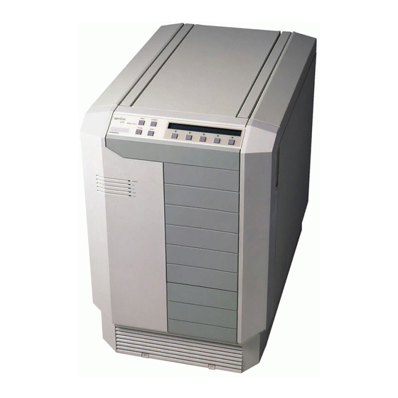
- Page 1 ADD-ON INSTALLATION GUIDE FT//s Pentium apricot MITSUBISHI ELECTRIC...
- Page 2 All rights reserved; no use or disclosure without written consent. Copyright © Apricot Computers Limited 1993 Published by Apricot Computers Limited 3500 Parkside Birmingham Business Park B37 7YS MITSUBISHI ELECTRIC Printed in the United Kingdom Part no. 15225231...
-
Page 3: Table Of Contents
Contents Introduction 2 Anti-static precautions 3 Power down procedure 4 Power up procedure 4 Removing the left side panel 5 Adapter cards 6 Upgrading memory 8 Processor upgrades 12... -
Page 4: Introduction
Introduction This guide contains instructions on installing expansion cards, extra memory and processor upgrades in your computer. This document should be your only source of information when installing any of these. You should read this document before purchasing extra memory or a processor upgrade. If, having read the relevant instructions, you are not confident about installing the upgrade, you may wish to have your supplier or service organisation install it for you. -
Page 5: Anti-Static Precautions
Anti-static precautions All electronic components and equipments are sensitive to static electricity. Even small electrostatic discharges can render components useless or severely shorten their working life, therefore you should always take preventive measures. No work should be carried out on any item unless it is in a Special Handling Area (SHA) as defined in BS CECC 00015:Part 1. -
Page 6: Power Down Procedure
Power down procedure If LOC Technology is in use, a user of appropriate authority must be logged on before the system can be powered down. 1. Push the button STANDBY 2. Confirm by pushing the button under the ‘Y’ on the LCD display. -
Page 7: Removing The Left Side Panel
Removing the left side panel The left side panel (as viewed from the front) is located by three pegs at the front, and secured by two thumbscrews and a keylock at the rear. The left side panel allows access to the electronics bay where the motherboard and power distribution board are located. -
Page 8: Adapter Cards
Adapter cards Eight 32-bit Micro Channel slots are available on the motherboard for adapter cards. One slot is always occupied by a hard disk controller. Each slot has a blanking plate in the rear panel, and a notch in the bridge assembly at the front of the system unit. - Page 9 It is recommended that slots 6 and 1 are left unoccupied (except for video cards), and slot 5 is left unoccupied (except for a second drive controller). Any other adapter cards should be fitted in slots 2, 3, 5 and 8 working down the system unit.
-
Page 10: Upgrading Memory
Upgrading memory The FT//s Pentium motherboard has eight SIMM sockets which support a maximum of 256 Mbytes of RAM. These eight sockets are arranged in two banks of four. If SIMMs are installed in a bank all four SIMMs must be identical. The eight SIMM sockets are located at the top front of the motherboard as shown in the following illustration. - Page 11 Apricot supplies and supports upgrades of 16, 32, 64 and 128 Mbyte capacities. The following table lists the possible capacities: Bank capacity (Mbytes) Total capacity Bank 0 Bank 1 (Mbytes) Note For all cases the SIMMs in bank 0 could be swapped with those in bank 1 with no adverse affect.
- Page 12 Installing SIMMs Obtaining access To obtain access to the SIMM sockets you must remove the left side panel as described in Removing the left side panel . Removing SIMMs If you wish to install an upgrade in a bank which is already occupied you must first remove the existing SIMMs.
- Page 13 2. Position the SIMM by the socket with the SIMM tilted slightly towards the rear of the system unit. 3. Lower the SIMM into the socket, and ensure that the SIMM is properly located in the connector. 4. Pushing gently on the top corners rotate the SIMM backwards until it clips into place.
-
Page 14: Processor Upgrades
Processor upgrades The FT//s Pentium motherboard is fitted with a Zero Insertion Force (ZIF) processor socket, ready for higher performance Pentium variants as they become available. The FT//s Pentium motherboard is ready to accept any processor with a Pentium compatible pinout, and a maximum external clock speed of 60MHz. - Page 15 The processor is installed in a ZIF socket. A lever attached to the socket clamps the processor securely in the socket when it is parallel to the motherboard. 5. Carefully rotate the lever from the secure position until it is perpendicular to the motherboard FREE LOCKED The first and last 15°...
- Page 16 Installation You are ready to install your new upgrade processor. 1. The upgrade processor and socket are keyed to ensure that the processor can only be installed in one orientation. One corner of the socket has an extra hole inside the others, the processor has a corresponding extra pin.
- Page 17 PROCESSOR IN CENTRE Warning If the processor is misaligned it will not go into the socket, and any attempt to force it will damage the processor, or the socket, or both. 3. Gently insert the upgrade processor making sure that it is correctly aligned with the socket and that you do not bend or otherwise damage the pins.
- Page 18 APRICOT COMPUTERS LIMITED 3500 PARKSIDE BIRMINGHAM BUSINESS PARK BIRMINGHAM B37 7YS. MITSUBISHI ELECTRIC Part No 15225231 Revision No 01...