Table of Contents
Advertisement
Quick Links
Advertisement
Table of Contents

Summary of Contents for Olivetti EXPLOR@460
- Page 1 User’s Manual EXPLOR@460...
-
Page 2: Liability Disclaimer
EXPLOR@460 Copyrights ©2016 All rights reserved. The information in this document is subject to change without prior notice in order to improve reliability, design and function and does not represent a commitment on the part of the manufacturer. This document contains proprietary information protected by copyright. All rights are reserved. No part of this manual may be reproduced by any mechanical, electronic, or other means in any form without prior written permission of the manufacturer. -
Page 3: Table Of Contents
EXPLOR@460 Contents Copyrights ....................ii Liability Disclaimer ................ii Regulatory Information ................ii CE Notice ......................ii Contents ....................iii 1. Hardware Setup .................. 4 1.1. Packing Contents ..................4 1.2. Quick Tour ..................... 5 Front View ...................... 5 Back View....................... 5 Back Panel I/O .................... -
Page 4: Hardware Setup
EXPLOR@460 Hardware Setup 1.1. Packing Contents 1. EXPLOR@460X 1 5. Recovery DVD x 1 2. Power Adapter X 1 6. Safety and Disposal Information Series X 1 3. EU Power Cord X 1 7. Drive and Utility DVD X 1 4. -
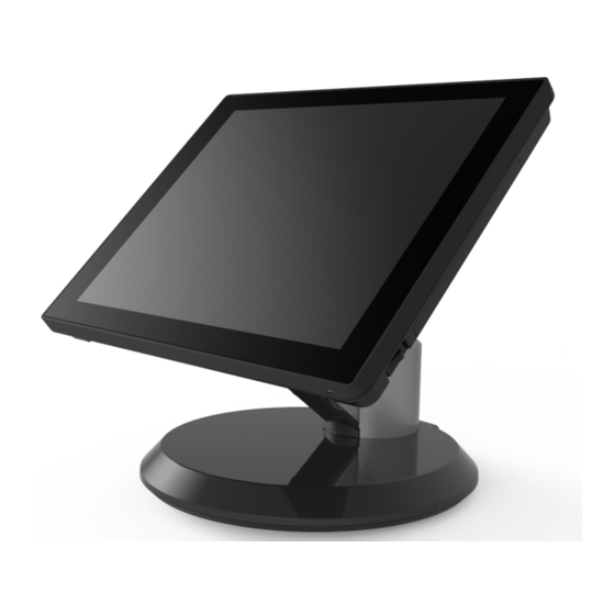
Page 5: Quick Tour
EXPLOR@460 1.2. Quick Tour Front View LED Indicator The Power indicator will glow green when power is on. Back View Customer Display mounting Power switch hole cover Hinge Cover I/O cover MSR cover Chapter 1... -
Page 6: Back Panel I/O
EXPLOR@460 Back Panel I/O 19VDC in 12VDC out USB 3.0 CD/DIO (for cash drawer) Mini Display Port COM1 COM3 COM2 USB2.0 x 4 CAUTION * Note: Please use 10-pin RJ50 connector, 8-pin RJ45 is incompatible. Chapter 1... -
Page 7: Basic Peripherals Installation
EXPLOR@460 1.3. Basic Peripherals Installation All cables and wires from peripherals to the POS device are recommended to connected as the direction as shown below. Power Adapter Important! Plug the AC adapter into the POS/PPC, and then connect to the mains power supply. -
Page 8: Usb Mouse, Usb Keyboard And Usb Odd
EXPLOR@460 USB Mouse, USB Keyboard and USB ODD Connect your USB Mouse, USB Keyboard and USB ODD to USB ports on the back panel of the device. LAN Cable Connect one end of RJ-45 LAN cable to the LAN port on the back panel of the device, another end to your internet device. -
Page 9: Cash Drawer
EXPLOR@460 Cash Drawer Connect one end of RJ-12 cable to the Cash Drawer port on the back panel of the device, another end to your cash drawer. Customer Display 1. Remover the customer display mounting hole cover from the device and pull out the connector from the device. - Page 10 EXPLOR@460 3. Mount the customer display to the device and tighten the two PHILLIPS M3 screws as shown below. 4. Finished. B. Power Supply Configuration Power up the device and hit the DEL key to enter the BIOS. When the BIOS screen appears use the TAB key to select Advanced.
- Page 11 EXPLOR@460 Caution: Never enable the 12 V without the customer display attached and be sure to disable the 12 V before removing the customer display. NOTE: The figure above is for reference only; it is possible that the actual screen on your device does not agree with it.
-
Page 12: 2Nd Display
EXPLOR@460 2nd Display 1. Make sure that all items (shipped with your 2nd display) listed below are ready. 2nd display support base bracket Plastic bush M3 screw X 4 Plastic spacer M4 screw X 2 2. Remove the 2nd display mounting hold cover from the base. - Page 13 EXPLOR@460 4. Feed one head of the cables (depends on your application) through the base of the device as shown below. 5. Remove the film on the back of the plastic spacer; and then stick the spacer to the base bracket as shown.
- Page 14 EXPLOR@460 8. Connect the heads of the cables to the ports of the back I/O panel of the 2nd display, and then tighten the four M3 screws to fix the 2nd display support onto the 2nd display as shown below.
- Page 15 EXPLOR@460 11. Install the IO panel cover onto the device. 12. Attach the front cable cover back to the base. 13. Finished. Now you can adjust the horizontal angle of the 2nd display. Chapter 1...
-
Page 16: Msr
EXPLOR@460 1. Remove the MSR cover from the device. 2. Connect the cable of the MSR assembly to the device. 3. Tighten the two PHILLIPS M3 screws to fix the MSR assembly as shown below. Chapter 1... - Page 17 EXPLOR@460 4. Finished. Note: The RS232 MSR is powered by COM5, Baud rate is 9000, 8, n, 1. Chapter 1...
-
Page 18: Adjust Angle
EXPLOR@460 1.4. Adjust Angle Chapter 1... -
Page 19: Turn On The Device
EXPLOR@460 1.5. Turn on the device 1. Make sure all peripherals are connected properly. 2. Press and hold the power switch until the power indicator on the front panel glow green. Power Switch Chapter 1... -
Page 20: I/O Definition
EXPLOR@460 I/O Definition Please refer the detailed technical information about all I/O ports as followings. 2.1. Power Connector Signal Name Signal Name Chapter 5... -
Page 21: Serial Port
EXPLOR@460 2.2. Serial Port R232 RS422 RS485 Chapter 5... -
Page 22: Vga Port
EXPLOR@460 2.3. VGA Port VGA DE-15 Description Description KEY/PWR GREEN BLUE ID0/RES ID2/RES ID1/SDA HSync RED_RTN VSync GREEN_RTN ID3/SCL BLUE_RTN Chapter 5... -
Page 23: Com 1.2 (10-Pin Rj50)
EXPLOR@460 2.4. COM 1.2 (10-Pin RJ50) Signal Name Signal Name XRIA_N XRXDA XDSRA_N XRTSA_N XCTSA_N XDTRA_N XTXDA XDCDA_N Chapter 5... -
Page 24: Cash Drawer
EXPLOR@460 2.5. Cash Drawer Description Description 12V / 19V D_OUT0 D_OUT1 D_IN Chapter 5... - Page 25 EXPLOR@460 Cash Drawer Control The Cash Drawer Controller use one I/O addresses to control the Cash Drawer. Register Location: 48Ch Attribute: Read / Write Size: 8-bit BIT7 BIT6 BIT5 BIT4 BIT3 BIT2 BIT1 BIT0 Attribute Reserved Read Reserved Write Reserved Reserved Cash Drawer “DOUT bit0”...
- Page 26 EXPLOR@460 Note: Please follow the Cash Drawer control signal design to control the Cash Drawer. Cash Drawer Control Command Example Use Debug.EXE program under DOS or Windows98 Command Cash Drawer O 48C 04 Opening O 48C 00 Allow to close Set the I/O address 48Ch bit2 =1 for opening Cash Drawer by “DOUT bit0”...
-
Page 27: Specification
EXPLOR@460 Specification Chapter 5... - Page 28 EXPLOR@460 Main Board Intel® Bay Trail-Mobile/Desktop SoC Processor: Celeron® J1900 Graphic Intel® HD Graphics System Memory Cooling Solution Fan-less Windows Embedded POSReady 7 Windows 7 Professional for Embedded Systems Windows Embedded 8.1 Industry Display 15" TFT LCD Panel Size Brightness...
- Page 29 EXPLOR@460 Black / Silver Color Material Plastic / Aluminum Certifications CE / WEEE / RoHS Dimension (W x D x H) 36.5x23x34.1cm (13.4x9x13.4inch) Net Weight / Gross 6.8kg, 15.1lb / 8.8 kg, 19.6lb Weight Operation Temperature 0 to 40°C Storage Temperature -20 ~ 60°C,...