
Related Manuals for AOpen DT2462M


Summary of Contents for AOpen DT2462M
-
Page 1: User Guide
MEDICAL GRADE TOUCH DISPLAY User Guide 23.8” LCD Touch Screen Monitor Model: DT2462M... -
Page 2: Table Of Contents
Table of Contents User Guide .............................. 1 Introduction ............................. 3 Monitor description ......................3 Box of contents ........................3 Product overview ........................ 4 Important Information ........................8 Safety information ......................8 Environmental information ....................10 Regulatory information ...................... 11 Equipment Symbols ......................12 Cleaning the Display ........................ -
Page 3: Introduction
1. Introduction 1.1 Monitor description The equipment is applied for healthcare that is intended for general use in hospital environment for data collection and display for reference. It shall not be used with life support system or for medical diagnosis. Type of equipment: Portable (on a table) Intended location: Medical environment Intended User Profile... -
Page 4: Product Overview
1.3 Product overview Front View The image below shows the front view of the display. Image 1-1 Front view 1. P-CAP touch 2. Bezel 3. LED 4 / 47... - Page 5 Side View The image below shows the control keys located in the right bottom corner of the display. Image 1-2 Control Key 1. Menu / Enter key / Scrolling key 5 / 47...
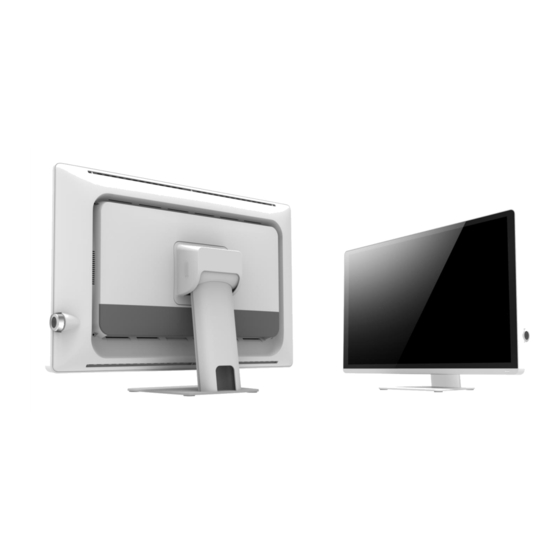
- Page 6 Rear View Image 1-3 Rear view 1. Rear cover 2. IO cover 3. Monitor stand 4. Hinge cover 6 / 47...
- Page 7 Available Connections Image 1-4 Available connections (bottom view) RS232 Audio Display Port POWER 7 / 47...
-
Page 8: Important Information
2. Important Information Safety information General recommendations Read the safety and operating instructions before operating the device. Save the safety and operating instructions for future reference. Adhere to all warnings on the device and in the operating instructions manual. Follow all instructions for operation and use. - Page 9 Power cords: • Do not overload wall outlets and extension cords as this may result in fire or electric shock. • Main leads protection (U.S.: Power cord): Power cords should be routed so that they are not walked upon or pinched by items placed upon or against them. Pay particular attention to cords at plugs and receptacles.
-
Page 10: Environmental Information
Environmental information Disposal Information Waste Electrical and Electronic Equipment This symbol on the product indicates that under the European Directive 2012/19/EU, governing waste from electrical and electronic equipment, this product must not be disposed of with other municipal waste. Please dispose of your waste equipment by handing it over to a designated collection point for the recycling of waste electrical and electronic equipment. -
Page 11: Regulatory Information
Regulatory information Indications for use The monitor (23.8” Touch Screen LCD monitor) is applied for healthcare that is intended for general use in hospital environment for data collection and display for reference. FCC class B This device complies with Part 15 of the FCC Rules. Operation is subject to the following two conditions: (1) This device may not cause harmful interference, and (2) this device must accept any interference received, including interference that may cause undesired operation. -
Page 12: Equipment Symbols
Equipment Symbols Electrical and electronic equipment symbols Indicates the device meets the requirements of the applicable EC directives. Indique que l'appareil satisfait aux exigences des directives CE en vigueur. Indicates compliance with Part 15 of the FCC rules Indique la conformité à la partie 15 des règles de la FCC. Indicates the device is approved according to the TUV regulations for Canada and US Indique que l'appareil est approuvé... - Page 13 Caution ATTENTION Consult accompanying documents. Consultez les documents accompagnés. Indicates this device must not be thrown in the trash but must be recycled, according to the European WEEE (Waste Electrical and Electronic Equipment) directive. Indique que cet appareil ne doit pas être jeté à la poubelle mais doit être recyclé, conformément à...
-
Page 14: Cleaning The Display
3. Cleaning the Display Cleaning instructions To clean the display Cleaning the display using a sponge, cleaning cloth, or soft tissue with lightly moistened recognized cleaning product for medical equipment. Read and follow all labeled instructions on the cleaning product. In case of doubt about a certain cleaning product, use plain water. CAUTION: ... -
Page 15: Emc Notice
EMC notice Electromagnetic emissions The monitor is intended for use in the electromagnetic environment specified below. The customer or the user of the monitor should assure that it is used in such an environment. Electromagnetic environment – Emissions test Compliance Guidance The monitor uses RF energy only for its internal function. - Page 16 Electromagnetic immunity The monitor is intended for use in the electromagnetic environment specified below. The customer or the user of the monitor should assure that it is used in such an environment. Immunity test Electromagnetic IEC 60601 Test levels Compliance level environment –...
- Page 17 Immunity test IEC 60601 Test levels Compliance level Electromagnetic environment – guidance Conducted RF Portable and mobile RF 3 V at 0,15 - 80MHz 3 V at 0,15 - 80MHz communications equipment IEC 61000-4-6 6 V at ISM bands 6 V at ISM bands should be used no closer to any part of the monitor, including cables, than the...
- Page 18 Recommended separation distance The monitor is intended for use in an electromagnetic environment in which radiated RF disturbances are controlled. The customer of the user of the monitor can help prevent electromagnetic interference by maintaining a minimum distance between portable and mobile RF communications equipment (transmitters) and the monitor as recommended below, according to the maximum output power of the communications equipment.
- Page 19 Pulse LTE Band 13, modulation b) 704-787 217 Hz GSM 800 / 900, Pulse TETRA 800, modulation b) 800-960 iDEN 820 18 Hz CDMA 850, LTE Band 5 GSM 1800; 1720 CDMA 1900; GSM 1900; Pulse modulation b) 1700-1990 DECT; 1845 LTE Band 1, 3, 217 Hz...
- Page 20 CAUTION The unit is for exclusive interconnection with IEC 60XXX certified equipment outside of patient environment and IEC 60601-1 certified equipment inside the patient environment. This device complies with EN60601-1-2, To minimize the interference from other equipment, a minimum 0.5 m distance shall be kept form other potential electromagnetic sources, such as the Cell Phone. The power cable connector is the primary means of detaching the system from the power supply.
- Page 21 ATTENTION L'unité est destinée à une interconnexion exclusive avec des équipements certifiés IEC 60XXX en dehors de l'environnement du patient et des équipements certifiés IEC 60601-1 à l'intérieur de l'environnement du patient. Cet appareil est conforme à la norme EN60601-1-2. Pour minimiser les interférences provenant d'autres équipements, une distance minimale de 0,5 m doit être maintenue par rapport à...
-
Page 22: Monitor Installation
4. Monitor Installation WARNING: Sufficient expertise is required to install this equipment. All devices and complete setup must be tested before operation. AVERTISSEMENT : Une expertise suffisante est requise pour l'installation de cet équipement. Tous les appareils et la configuration complète doivent être testés avant d'être mis en service. -
Page 23: Stand Removal & Vesa Mount Installation
4.2 Stand removal & VESA mount installation This monitor provided with a validated stand. The monitor has been designed to be used in landscape position with a maximum tilt of -5° to 30° backward. If a different stand is needed in the final application, the monitor VESA interface (VESA 100 mm standard) could be used. - Page 24 Image 4-2-2 Remove the 4x M4 screws Image 4-2-3 Remove the stand from the monitor 24 / 42...
- Page 25 5. Attach the monitor in landscape position to a 100 mm VESA mounting bracket. Mounting in portrait position is not feasible. Image 4-2-4 VESA mount is located at the back of the monitor. 25 / 42...
-
Page 26: Daily Operation
5. Daily Operation 5.1 Main power switch The monitor is switched on or off with the main switch, sees image 1-2 Control key. 5.2 Power/Status indication During start-up the monitor performs signal detection before going into normal operation mode. Depending on the detection result, the status LED on the side of the monitor will show different LED color. -
Page 27: Osd Menu Operation
6. OSD Menu Operation The Charts displays the function tree and brief explanations of the functions. Color, OSD, and other adjustments have submenus under each tree. 6.1 On-Screen Display The LCD monitor features an On-Screen Display (OSD) menu with easily identifiable icons designed to make adjustment of your monitor display settings a more user-friendly process. - Page 28 Color Mode Clock/Phase olor Mode Exit Exit Color Temperature Clock Exit Phase 9300K Audio 6500K Exit 5400K Input User Exit Exit Digital Line In Green Mute Blue Exit Gamma Exit Natural Volume Gamma 2.2 DICOM Management Exit Scaling Source Exit Exit Full Auto Select...
-
Page 29: Main Menu
6.4 Main Menu MAIN MENU D Exit Auto Setup T K Brightness Contrast L U Display Color Mode V Clock / Phase 0 Audio ] Management X Operating Hours O : Enter N S + / - Image 6-4 Main OSD menu 6.4.1 Exit To exit the OSD menu. -
Page 30: Brightness
6.4.3 Brightness This function allows the user to adjust the monitor’s brightness setting manually. Brightenss ㄎㄙㄙㄙㄙㄙㄙㄙㄙㄙㄙㄙㄙㄙㄙㄙㄘㄧ 100 Image 6-4-3 Brightness OSD menu 6.4.4 Contrast This function allows the user to adjust the contrast setting of the monitor manually. Contrast ㄎㄙㄙㄙㄙㄙㄙㄙㄙㄙㄙㄙㄙㄙㄙㄙㄘㄧ 100 Image 6-4-4 Contrast OSD menu 6.4.5 Display (Only Support Analog) Display... -
Page 31: Color Mode
• V. Position: The function allows users manually adjust the image position vertically on the screen. V. Position ㄎㄙㄙㄙㄙㄙㄙㄙㄙㄙㄙㄙㄙㄙㄙㄙㄘㄧ 100 Image 6-4-5-2 V. Position OSD menu 6.4.6 Color Mode Color Mode Exit D Color Temperature G Gamma ! Image 6-4-6 Color Mode OSD menu ... -
Page 32: Clock / Phase (Only Support Analog)
Red: Adjust red and equivalent colors at the range from 0 to 100. The greater the value is, the deeper the color is, and vice versa. Green: Adjust green and equivalent colors at the range from 0 to 100. The ... -
Page 33: Audio
Phase: Allows users to adjust the phase of the display setting manually. Phase ㄎㄙㄙㄙㄙㄙㄙㄙㄙㄙㄙㄙㄙㄙㄙㄙㄘㄧ 100 Image 6-4-7-2 Phase OSD menu 6.4.8 Audio Audio Exit D Input @ = Mute ] Volume Image 6-4-8 Audio OSD menu Exit: To exit the Audio of the OSD menu. ... -
Page 34: Management
Volume: Allows users to adjust the audio output of the display setting. Volume ㄎㄙㄙㄙㄙㄙㄙㄙㄙㄙㄙㄙㄙㄙㄙㄙㄘㄧ 100 Image 6-4-8-3 Audio Volume OSD menu 6.4.9 Management Management D Exit Scaling < OSD Display W Language 4 Source Y Power Key Lock # Recall 5... -
Page 35: Osd Display
6.4.9.2 OSD Display OSD Display Exit D OSD H. Position 9 OSD V. Position [ Image 6-4-9-2 OSD Display menu Exit: To exit the OSD Display of the OSD menu. OSD H. Position: Allows users to set OSD menu in horizontal position on the display. -
Page 36: Source
6.4.9.4 Source Source Exit D Auto Source > F E E Image 6-4-9-4a Source OSD menu Exit: To exit the Source of the OSD menu. Auto Source: Allows users to Enable or Disable the Auto Select function of the display setting. -
Page 37: Recall
6.4.9.6 Recall Exit: To exit the Recall function of the OSD menu. Yes: Allows users to recall the display setting back to factory default setting. Recall Exit D A Image 6-4-9-6 Recall OSD menu 6.4.10 Operating Hours Keep records of the monitor operating hours. -
Page 38: Supported Video Modes
6.5 Supported Video Modes ※Compliant Graphic Signal Timing (VGA, DVI & DP) Pixel-rate Frame-rate Resolution Line-rate [kHz] [MHz] [Hz] 640x480 25.200 31.500 60.000 640x480 31.500 37.861 72.809 640x480 31.500 37.500 75.000 720x400 28.322 31.469 70.087 800x600 36.000 35.156 56.250 800x600 40.000 37.879 60.317... -
Page 39: Technical Specifications
7. Technical Specifications Product description DT2462M / 23.8” LCD Touch Screen Monitor Screen technology AHVA Active screen size (diagonal) 604.70 mm (23.81”) Active screen size (H x V) 527.04 mm (H) x 296.46 mm (V) Aspect ratio (H:V) 16:9 Resolution... - Page 40 Dimensions (W x H x D) 581 x 400 x 175 mm Dimensions packed 702 x 277 x 526 mm (W x H x D) Net Weight with stand 9.3 kg ± 0.2 kg Tilt Angle -5 ±2 and 30 ±2 degrees Mounting standard VESA (100 x 100 mm) Certifications...
-
Page 41: Outline Dimension
8. Outline Dimension Image 8-1 Outline dimension 41 / 42... - Page 42 Image 8-2 Outline dimension with monitor tilt -5° & 30° backward 42 / 42...
- Page 43 AOPEN Rosmalen Netherlands Stadionlaan 151 -153, 5246 JT Phone (+31) 73 646 6400 AOPEN DT2462M User Guide 20200818 v0 43 / 42...