Hach Polymetron 9610sc SiO2 Installation Manual
Hide thumbs
Also See for Polymetron 9610sc SiO2:
- Installation manual (164 pages) ,
- Operation manual (468 pages) ,
- Installation manual (478 pages)
Advertisement
Quick Links
Advertisement

Related Manuals for Hach Polymetron 9610sc SiO2


Summary of Contents for Hach Polymetron 9610sc SiO2
- Page 1 DOC023.97.80246 Polymetron 9610sc Si0 , OS/2013 Edition 1 Installation...
- Page 3 Table 1 General specifications (continued) Table of contents Specifications on page 3 Specification Details General information on page 4 Maximum altitude 2000 m (6560 ft) Installation on page 7 Four; load impedance: 600 Ω maximum 4–20 mA outputs Connection: 22 to 16 AWG wire, 22 to 20 AWG recommended, twisted pair shielded wire Specifications Alarm relay outputs...
- Page 4 C A U T I O N Container: 2 L, PETE with polypropylene caps Indicates a potentially hazardous situation that may result in minor or moderate The accuracy is based on using Hach supplied reagents only. injury. General information N O T I C E Indicates a situation which, if not avoided, may cause damage to the instrument.
- Page 5 on the instrument, will be included with a danger or caution statement in This symbol identifies the presence of a strong corrosive or other the manual. hazardous substance and a risk of chemical harm. Only individuals qualified and trained to work with chemicals should handle chemicals This is the safety alert symbol.
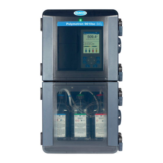
- Page 6 protection against harmful interference when the equipment is operated Figure 1 Product overview in a commercial environment. This equipment generates, uses and can radiate radio frequency energy and, if not installed and used in accordance with the instruction manual, may cause harmful interference to radio communications.
- Page 7 W A R N I N G Figure 2 Door removal Personal injury hazard. Instruments or components are heavy. Use assistance to install or move. W A R N I N G Personal injury hazard. The object is heavy. Make sure that the instrument is securely attached to a wall, table or floor for a safe operation.
- Page 8 Figure 4 Ports for four sample streams Figure 3 Ports for one or two sample streams 1 Not used 9 Sample 1 inlet 5 Sample 2 bypass drain 2 Sample 4 bypass 6 Sample 1 bypass 10 Sample 2 inlet drain drain 1 Drain vent-keep open...
- Page 9 N O T I C E Figure 5 Ports for six sample streams Do not connect the drain lines to other lines or backpressure and damage to the analyzer can occur. Make sure that the drain lines are open to air. N O T I C E To prevent backpressure and damage to the analyzer, make sure that the analyzer is higher than the facility drain(s) used and that the drain line has a...
- Page 10 • Collect samples from locations that are sufficiently distant from points Figure 6 Sample and drain lines of chemical additions to the process stream. • Make sure that the samples are sufficiently mixed. • Make sure that all chemical reactions are complete. Connect the sample stream Install each sample line into the center of a larger process pipe to minimize interference from air bubbles or bottom sediment.
- Page 11 The bypass flow can be adjusted when the analyzer is in shutdown Figure 9 Bypass flow rate adjustment - multi-streams mode. Adjust the flow rate of the sample bypass line with the flow valve as shown in Figure 8 Figure 9.
- Page 12 W A R N I N G D A N G E R Electrical shock and fire hazards. For a cord-connected instrument, Electrocution hazard. Do not connect AC power directly to a DC make sure to install the instrument so that the cord can be powered instrument.
- Page 13 Remove the access cover Figure 12 Connections on the main circuit board Remove the access cover to connect to the wiring terminals. Refer to Figure Figure 11 Access cover removal 1 Dual monitor 4 Digital inputs 7 Power out connection Wiring connections overview 2 Smart probe 5 Power in...
- Page 14 Table 3 AC wiring information (AC models only) W A R N I N G Electrical shock and fire hazards. Make sure that the supplied cord and non- locking plug meet the applicable country code requirements. Terminal Description Color—North Color—EU America W A R N I N G Protective Earth (PE)
- Page 15 Connect a dual monitor Figure 13 Power connection An external sc controller can connect to the analyzer. Connect a Hach cable 6789400 to the external sc controller and the dual monitor connection of the analyzer. Refer to Wiring connections overview on page 13.
- Page 16 Connect to the relays Figure 14 Device connection D A N G E R Electrocution hazard. Do not mix high and low voltage. Make sure that the relay connections are all high voltage AC or all low voltage DC. C A U T I O N Fire hazard.
- Page 17 Connect to the digital inputs Figure 15 Isolated TTL type digital input The analyzer can receive a digital signal from an external device, such as a flow meter to stop measurements when flow stops. Each discrete input is used to enable/disable the corresponding sample channel. Each digital input can be configured as an isolated TTL type digital input or as a relay/open-collector type input.
- Page 18 Install the stir bar Install the analyzer bottles A stir bar is included in the installation kit. Prior to the installation, C A U T I O N remove the funnel cover, funnel and colorimeter cover. Refer to Figure 17. Install the stir bar in the sample cell of the colorimeter as shown in the illustrated steps.
- Page 19 Figure 18 Stir bar installation Preparation for use The physical installation is now complete. Refer to the operations manual to set up the analyzer for the first use. English 19...
- Page 20 Tel. +49 (0) 2 11 52 88-320 SWITZERLAND Fax (970) 669-2932 Fax +49 (0) 2 11 52 88-210 Tel. +41 22 594 6400 orders@hach.com info@hach-lange.de Fax +41 22 594 6499 www.hach.com www.hach-lange.de © Hach Company/Hach Lange GmbH, 2013. All rights reserved. Printed in U.S.A.
- Page 21 DOC023.97.80269 Polymetron 9610sc Si0 , OS/2013 Edition 1 Operations...
- Page 22 Table of contents Use of hazard information D A N G E R General information on page 3 Indicates a potentially or imminently hazardous situation which, if not avoided, will User interface and navigation on page 5 result in death or serious injury. Startup on page 7 W A R N I N G...
- Page 23 Product overview This symbol indicates that a risk of electrical shock and/or electrocution exists. D A N G E R Chemical or biological hazards. If this instrument is used to monitor a treatment process and/or chemical feed system for which there are This symbol indicates that the marked item can be hot and should not regulatory limits and monitoring requirements related to public health, be touched without care.
- Page 24 Status indicator light Figure 2 Keypad description When the analyzer power switch is on, a status indicator light is on. Refer to Table Table 1 Status indicator definitions Light color Definition Green The analyzer is in operation with no warnings, errors or reminders. Yellow The analyzer is in operation with active warnings or reminders.
- Page 25 Figure 3 Measurement screen Figure 4 System status screen 1 Calibration status information 3 Reagent (Rx) and standards (Sx) 1 Home (main measurement screen) 6 Relays (second icon shown if with fluid level indicators (%) additional relay installed) 2 PROGNOSYS service indicator bar 4 PROGNOSYS measurement 2 Measurement channel 7 Parameter...
- Page 26 Additional display formats 3. Select an option. From the main measurement screen, additional display formats are Option Description available: MEASUREMENT Set the measurement value for the selected VALUE channel. Select between AUTO SCALE and • Single channel analyzers: MANUALLY SCALE. Enter the minimum and maximum ppb value in the MANUALLY SCALE •...
- Page 27 3. Stir the solution until the reagent fully dissolves. Items to collect: 4. Let the solution temperature decrease to approximately 25 °C. • Concentrated sulfuric acid, H , 95–97%, analytical quality, 25 mL 5. Dilute to the mark with deionized water. Mix fully. •...
- Page 28 3. Stir the water and slowly add a small quantity of the sulfuric acid. The 4. Close the analytics panel. solution becomes warm. Stir the solution again and add the remaining sulfuric acid in small quantities. The solution becomes hot. Start the analyzer setup 4.
- Page 29 100% full. IMPORTANT: make sure to push LEVELS enter, then select USER PREPARED STANDARDS if the standards were prepared in-house. Select HACH W A R N I N G PREPARED STANDARDS if the standards were Potential fire and explosion hazard. This equipment is intended for only aqueous prepared by the manufacturer.
- Page 30 • GRAB SAMPLE OUT: This option is used to extract a sample directly 2. Select one of the options. from a sample line for external analysis. Option Description Measure a grab sample or standard MEAS MODE Changes the mode of the measurement cycle. Use the grab sample funnel to measure grab samples taken from other Options: interval or continuous (default).
- Page 31 Set up the calculation Option Description Set up variables, parameters, units and formulas for the analyzer. MANAGE DEVICES Installs or removes input modules. Refer to Manage devices on page 12 for more information. 1. Select CALCULATION. INSTRUMENT Shows the analyzer information. Refer to View 2.
- Page 32 4. Select SET FUNCTION>PID CONTROL and then select the Option Description applicable options in the ACTIVATION menu. SELECT Select the output. Options: None if the output is not SOURCE configured, the analyzer name or calculation if a Option Description calculation formula has been configured. Refer to Set up SET MODE AUTO—the signal is automatically controlled by the...
- Page 33 5. Select SET FUNCTION>LOGARITHMIC and then select the Option Description applicable options in the ACTIVATION menu. SET FUNCTION Selects a function. ALARM—The relay starts when the upper or lower alarm value is triggered. FEEDER Option Description CONTROL—The relay shows if a process value is larger SET 50% VALUE Sets the value corresponding to 50% of the process or falls below a setpoint.
- Page 34 Option Description Option Description OFF DELAY Sets a delay time (0–300 seconds) to set the relay off OffMax TIMER Sets the maximum time the relay stays off (default = (default = 5 seconds). 0 min). ON DELAY Sets a delay time (0–300 seconds) to set the relay on OnMin TIMER Sets the time the relay stays on, independent from the (default = 5 seconds).
- Page 35 Table 2 Analyzer data (continued) Set the error hold mode Element Definition 1. Select SETUP SYSTEM>SETUP OUTPUTS>ERROR HOLD MODE. SAMPLE TEMP Sample pre-heater block temperature (typically 45 °C to 2. Select an option. 55 °C (113 °F to 131 °F) but could reach 58 °C (136.4 °F)) Option Description...
- Page 36 LINK2SC-compatible photometers. Use an SD memory card for the data exchange. Refer to the LINK2SC Reference A/D count used to compensate for natural documentation on http://www.hach.com for a detailed description of the color and turbidity. LINK2SC procedure.
- Page 37 manufacturer recommends to use an SD card with a minimum of 2 GB 4. When the upgrade is complete, the display shows TRANSFER storage capacity. COMPLETE. Remove the SD card. 5. Restart the instrument for the upgrade to take effect. 1.
- Page 38 3. Select STD SOLUTION and enter the standard value in ppb. 4. Select a schedule option for calibration. Option Description TIME BASE Sets the interval between calibrations. Options: DAYS or HOURS. WEEK DAY Selects the day or days of the week for calibration when TIME BASE is set to DAY.
- Page 40 Tel. +49 (0) 2 11 52 88-320 SWITZERLAND Fax (970) 669-2932 Fax +49 (0) 2 11 52 88-210 Tel. +41 22 594 6400 orders@hach.com info@hach-lange.de Fax +41 22 594 6499 www.hach.com www.hach-lange.de © Hach Company/Hach Lange GmbH, 2013. All rights reserved. Printed in U.S.A.
- Page 41 Polymetron 9610sc Si0 , OS/2013 Edition 1 Maintenance and Troubleshooting...
- Page 42 English ........................................3 Français ......................................15 Español .......................................27 Português ......................................40 中文 ........................................52 日本語 ........................................63 한글 ........................................75 ไทย ..........................................87...
- Page 43 Table of contents Use of hazard information D A N G E R General information on page 3 Indicates a potentially or imminently hazardous situation which, if not avoided, will Maintenance on page 4 result in death or serious injury. Troubleshooting and diagnostics on page 10 W A R N I N G...
- Page 44 Maintenance schedule This symbol indicates that a risk of electrical shock and/or electrocution exists. Table 1 shows the recommended schedule of maintenance tasks. Facility requirements and operating conditions may increase the frequency of some tasks. This symbol indicates that the marked item can be hot and should not Table 1 Maintenance schedule be touched without care.
- Page 45 View maintenance information Put the analyzer back into operation Use the service menu to view or reset the service history for the After maintenance tasks are complete, start the analyzer. instrument parts. 1. Make sure that all the tubing is connected and that the lower door is 1.
- Page 46 New tubing, valves and other sample conditioning equipment may be Figure 1 Funnel and colorimeter access contaminated with silicate-based substances (oils, dust). These may contribute to slightly high readings until they are cleaned. 1. Flush the sample line with sample for one to two hours. 2.
- Page 47 Clean the grab sample funnel Figure 2 Clean the sample cell and stir bar Clean the grab sample funnel before and after each use. Refer to Figure Figure 3 Clean the grab sample funnel Replace the reagent(s) or standard(s) C A U T I O N Chemical exposure hazard.
- Page 48 Replace the reagent(s) or standard(s) before the level in the analyzer D A N G E R bottle(s) is less than 10%. Measurements are not accurate when the level is less than 10%. Fire hazard. Use the same type and current rating to replace fuses. 1.
- Page 49 Prepare the analyzer for storage Figure 5 Replace the fuses C A U T I O N Chemical exposure hazard. Obey laboratory safety procedures and wear all of the personal protective equipment appropriate to the chemicals that are handled. Refer to the current safety data sheets (MSDS/SDS) for safety protocols.
- Page 50 3. Select UPGRADE SOFTWARE and confirm. Select the device and Option Description upgrade version, if applicable. CURRENT Shows the current instrument statuses that follow: 4. When the upgrade is complete, the display shows TRANSFER STATUS OPERATION—Current measurement mode. SAMPLE COMPLETE. Remove the SD card. CHANNEL—Current sample channel.
- Page 51 Option Description Option Description SYSTEM DATA Shows the system information. TEMPERATURE— OUTPUT Shows the current status outputs 1–4. Shows the measured temperature of the A/D device in STATUS Celsius (C). POWER SOURCE FREQUENCY—Shows SIMULATE Shows only when a sensor or module is connected. After the line power frequency (Hz).
- Page 52 Start an analyzer test Option Description The user can complete tests to check the analyzer operation. AIR PUMP Change and control the air pressure. SET SETPOINT—Range: 1–9.99 psi. LOW and HIGH DEADBAND—Range: 0–1 psi. SET LOW and HIGH 1. Push diag, then select PERFORM TEST. VALUE—Range: 5–99.99 psi.
- Page 53 Replacement parts and accessories (continued) Replacement parts and accessories (continued) Description Item no. Description Item no. Colorimeter assembly, LR phosphate 6786801 Reagent bottle tray 6765900 Colorimeter assembly, HR phosphate 6786802 Stir bar 6772600 Colorimeter cell 6768000 Y strainer 6784800 Colorimeter cover 6766900 Accessories Fan filter plug...
- Page 54 Replacement parts and accessories (continued) Description Quantity Item no. Standard 1 HR Phosphate, 9611sc 2037102 Stainless steel sample adapter kit 6786600 Sample cooler 1757700 Sodium Hydroxide Solution, 1 N (5%), 900 mL 104553 Sodium Hydroxide Solution, 1 N (5%), 3.60 L 104517 14 English...
- Page 55 Tel. +49 (0) 2 11 52 88-320 SWITZERLAND Fax (970) 669-2932 Fax +49 (0) 2 11 52 88-210 Tel. +41 22 594 6400 orders@hach.com info@hach-lange.de Fax +41 22 594 6499 www.hach.com www.hach-lange.de © Hach Company/Hach Lange GmbH, 2013. All rights reserved. Printed in U.S.A.