Table of Contents
Advertisement
Quick Links
Advertisement
Table of Contents

Summary of Contents for ESI KPG Series
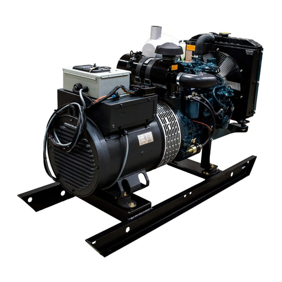
- Page 1 OPERATIONS & MAINTENANCE MANUAL ESI Designed and built Kubota 03 Series Diesel Engine Mecc Alte ECP or ECO Gen End APplicable models KPG-14-D15-MR2S KPG-15-D17-MR2S KPG-18-V20-MR2S KPG-20-V22-MR2S KPG-23-V20T-MR2S KPG-24-V24-MR2S www.ESIalaska.com...
- Page 2 ESIalaska.com THIS PAGE INTENTIONALLY LEFT BLANK Anchorage: Fairbanks: Seattle: Williston: 7780 Old Seward Hwy 1919 Van Horn Road 17660 W. Valley Hwy 5064 Bennett Loop Anchorage, AK 99518 Fairbanks, AK 99701 Tukwilla, WA 98188 Williston, ND 58801 (907) 341-2250 | (877) 341-2250 (907) 458-9049 | (888) 868-9049 (425) 251-6119 (701) 774-5312...
- Page 3 ESIalaska.com General Information & Warranty Anchorage: Fairbanks: Seattle: Williston: 7780 Old Seward Hwy 1919 Van Horn Road 17660 W. Valley Hwy 5064 Bennett Loop Anchorage, AK 99518 Fairbanks, AK 99701 Tukwilla, WA 98188 Williston, ND 58801 (907) 341-2250 | (877) 341-2250 (907) 458-9049 | (888) 868-9049 (425) 251-6119 (701) 774-5312...
- Page 4 ESIalaska.com THIS PAGE INTENTIONALLY LEFT BLANK Equipment Source, Inc.
- Page 5 OPERATORS MANUAL KPG Generator Kubota Powered Generators by ESI SPECIFICATIONS See product specification sheet for product www.ESIalaska.com specifications For Parts & Service: Fairbanks, Alaska 907.458.9049 FAI-Parts@ESIalaska.com Anchorage, Alaska 907.341.2250 ANC-Parts@ESIalaska.com Seattle, Washington 425.251.6119 FAI-Parts@ESIalaska.com Williston, North Dakota 701.774.5312 Williston-Sales@ESIalaska.com Anchorage:...
- Page 6 Read and understand this manual before operating the machine to avoid serious injury or death. General Description ESI built KPG generators come in a variety of configurations and sizes. Refer to unit specifications and manual components for specific details. General operation and maintenance remains the same for all of these units.
- Page 7 KPG GENERATOR IMPORTANT SAFETY INSTRUCTIONS 2 IMPORTANT SAFETY INSTRUCTIONS WARNING SAVE THESE INSTRUCTIONS. This manual contains important instructions that should be followed during the operation and maintenance of the generator, battery and heater. Training Never allow untrained personnel to operate or service the machine. Take time to read the ...
- Page 8 Units placed in storage must be stored out of the elements and protected from rain, snow and sunlight. The warranty will be voided for units left exposed to the elements during storage. ESI built unit enclosures provide sufficient protection when properly closed.
- Page 9 Refer to the ESI Warranty Summary for further details. Consider using a load bank to maintain minimum loading on the engine.
- Page 10 KPG GENERATOR Operation Long Run Oil Tank (LRT) A LRT equipped ESI generator has increased service intervals up to 3000 hours o Oil change intervals should be determined using an oil sample analysis at regular intervals to determine maximum service interval.
- Page 11 KPG GENERATOR Maintenance Records 5 Maintenance CAUTION Some of the following maintenance operations should only be completed by a trained technician. Do not attempt to open electrical panels unless you are a trained technician. Maintenance schedule must be adhered to and documented in order to maintain warranty.
- Page 12 KPG GENERATOR Maintenance Records Every Year Replace air cleaner element Air filter element Clean Generator (blow out with air) and inspect may need cleaning Change Engine Oil and Oil Filter more frequently depending on environmental conditions Every 800 hours Check valve clearance ...
- Page 13 KPG GENERATOR Maintenance Records 6 Maintenance Records Table 2. Machine Data Machine Serial Number Engine Serial Number Generator Serial Number Table 3. Maintenance Records Date Engine Hours Service Description of work completed Personnel Service Location Rev August 2019 | Copyright © 2019 Equipment Source, Inc...
- Page 14 KPG GENERATOR Maintenance Records Rev August 2019 | Copyright © 2019 Equipment Source, Inc...
- Page 15 KPG GENERATOR Maintenance Records Rev August 2019 | Copyright © 2019 Equipment Source, Inc...
- Page 16 KPG GENERATOR Maintenance Records Rev August 2019 | Copyright © 2019 Equipment Source, Inc...
- Page 17 ESIalaska.com Commonly Replaced KPG Parts See next page for LRT options and remote fuel filters when applicable Kubota Model Oil Filter Air Filter Fuel Filter Oil Capacity Engine KPG-05 Z482 15426-32430 P822686 12581-43012 2.6 Liters / 0.69 Gal KPG-06-NG DG972 3.4 Liters / 0.90 Gal HH150-32430 1G659-11222...
- Page 18 ESIalaska.com This Page Intentionally Blank Equipment Source, Inc.
- Page 19 Misc GCI Spec Generators Phase Configuration TCC = TCC Clinic Back Up Reconectable 12-Lead Gen End Make Dedicated Single Phase Mecc Alte 4-Lead Stamford Dedicated Three Phase Marathon Dedicated Three Phase Switchable: 208/240 to 240/480 K:\00_Literature\32_Price Book\00_Working Files\ESI Product Pricing and Inventory...
- Page 20 ESIalaska.com THIS PAGE INTENTIONALLY LEFT BLANK Anchorage: Fairbanks: Seattle: Williston: 7780 Old Seward Hwy 1919 Van Horn Road 17660 W. Valley Hwy 5064 Bennett Loop Anchorage, AK 99518 Fairbanks, AK 99701 Tukwilla, WA 98188 Williston, ND 58801 (907) 341-2250 | (877) 341-2250 (907) 458-9049 | (888) 868-9049 (425) 251-6119 (701) 774-5312...
- Page 21 No person, agent or dealer is authorized to give any between the skid and mounting surface) voids the warranties on the behalf of ESI, nor is to assume for this warranty. Consult the product operator’s manual for company any other liability in connection with any of ESI’s required installation procedures.
- Page 22 Learn how to operate and work safely. Know your the repair or replacement of defective parts. IN NO EVENT equipment and its limitations. Always keep the engine WILL ESI BE LIABLE FOR LOSS OF USE, LOSS OF PROFITS, in good condition. LOSS...
- Page 23 KUBOTA ENGINE AMERICA CORPORATION LIMITED WARRANTY ON INDUSTRIAL ENGINES AND REPLACEMENT PARTS EFFECTIVE JANUARY 1, 2009 OUR WARRANTY TO YOU engine installation to optimize functionality/performance within the We warrant to you, the original purchaser, that all parts (except those OEM’s equipment order maintain...
- Page 24 ESI highly recommends that skid mounted generators be installed with adequate fluid containment and other safeties including but not limited to remote monitoring. The installer and operator of the generator must adhere to all laws and regulations governing the installation and operation of the generator.
- Page 25 ESIalaska.com Alternator Manual Anchorage: Fairbanks: Seattle: Williston: 7780 Old Seward Hwy 1919 Van Horn Road 17660 W. Valley Hwy 5064 Bennett Loop Anchorage, AK 99518 Fairbanks, AK 99701 Tukwilla, WA 98188 Williston, ND 58801 (907) 341-2250 | (877) 341-2250 (907) 458-9049 | (888) 868-9049 (425) 251-6119 (701) 774-5312 Equipment Source, Inc.
- Page 26 ESIalaska.com THIS PAGE INTENTIONALLY LEFT BLANK Equipment Source, Inc.
- Page 27 ALTERNATORI AUTOREGOLATI SERIE ECO-ECP ISTRUZIONI PER L’USO E LA MANUTENZIONE SELF- REGULATING ALTERNATORS SERIES ECO-ECP OPERATING AND MAINTENANCE INSTRUCTIONS ALTERNATEURS AUTO - REGULES SERIE ECO-ECP MANUEL D’INSTRUCTION ET DE MAINTENANCE SELBSTREGELNDER GENERATOR SERIE ECO-ECP BETRIEBS-UND WARTUNGSANLEITUNG ALTERNADORES AUTOREGULADOS SERIE ECO-ECP INSTRUCCIONES PARA USO Y MANTENIMIENTO...
- Page 28 INDEX INDICE 2 ÷ 3 DESCRIZIONE MACCHINA MACHINE DESCRIPTION 4 ÷ 5 PREMESSA INTRODUCTION 4 ÷ 5 IDENTIFICAZIONE MACCHINA MACHINE IDENTIFICATION 4 ÷ 5 VERIFICA ALLA CONSEGNA INSPECTION ON DELIVERY 4 ÷ 13 PRESCRIZIONI DI SICUREZZA SAFETY REQUIREMENTS 14 ÷ 17 TRASPORTO E IMMAGAZZINAMENTO TRANSPORT AND STORAGE 16 ÷...
- Page 29 PREMESSA INTRODUCTION I generatori della serie ECO-ECP, rispondono The ECO-ECP alternators comply with the alle direttive CEE 2006/42, 2006/95, EEC 2006/42, 2006/95, 2004/108 directives 2004/108 e relative modifiche; pertanto non and their amendments; therefore they pose presentano pericolo per l’operatore, se no danger to the operator if they are installed, installati, usati, manutenuti secondo le used and maintained according to the...
- Page 30 PRESCRIZIONI SAFETY DI SICUREZZA REQUIREMENTS Durante la consultazione del presente In consulting this use and maintenance manuale d’uso e manutenzione troverete manual, you will find several symbols, which alcuni simboli; questi hanno un preciso have a specific meaning, as illustrated below. significato qui di seguito illustrato.
- Page 31 PRESCRIZIONI SAFETY DI SICUREZZA REQUIREMENTS ADDETTO ALLA MOVIMENTAZIONE HANDLER Identifica il tipo di operatore a cui è This symbol identifies the type of riservato l’intervento trattato. operator in charge of the operation Questa qualifica presuppone una piena described. conoscenza e comprensione delle This qualification requires a complete informazioni contenute nel manuale knowledge and understanding of the...
- Page 32 PRESCRIZIONI SAFETY DI SICUREZZA REQUIREMENTS Before installing the generator, arran- Al momento dell’installazione le norme gements must be made to earth the prevedono che il generatore sia collegato a machine. This is the reason why you must terra. make sure that the grounding system is in Per questa ragione assicurarsi che l’impianto good conditions and in compliance with the di messa a terra sia efficiente ed in...
- Page 33 SAFETY PRESCRIZIONI REQUIREMENTS DI SICUREZZA Nelle vicinanze della macchina non ci devo- No person must wear fluttering clothes (such no essere persone con indumenti svolaz- as scarves, etc.) near the machine and any zanti tipo: sciarpe, fular, bracciali, etc e garment must be fastened with elastic bands qualsiasi indumento deve essere chiuso con at its ends.
- Page 34 TRASPORTO E TRANSPORT IMMAGAZZINAMENTO AND STORAGE GEFAHR PERICOLO PELIGRO DANGER In funzione della destinazione, gli alternatori Alternators will be packed for shipment in a possono essere imballati per la spedizione in manner suitable to their mode of transport vari modi. and final destination.
- Page 35 TRASPORTO E TRANSPORT IMMAGAZZINAMENTO AND STORAGE Ricordarsi che, una volta che il generatore Once the generator is coupled with an sara’ accoppiato al motore primario, o engine, mounted on a baseframe, or installed montato su un basamento, o installato in un on a complete generating set, it cannot be telaio in modo da formare un corpo unico, lifted by its lifting bolts.
- Page 36 MECHANICAL ACCOPPIAMENTO COUPLING MECCANICO ISTRUZIONI PER MONTAGGIO IN INSTRUCTIONS FOR THE ASSEM- FORMA COSTRUTTIVA MD35. BLING GENERATORS WITH Un allineamento impreciso può causare MD35 FORM. vibrazioni e danneggiamenti dei A bad alignment may cause vibrations cuscinetti. E’ consigliabile inoltre and bearing damages. It is advisable to verificare compatibilità...
- Page 37 MECHANICAL ACCOPPIAMENTO COUPLING MECCANICO g) inserire ed avvitare parzialmente la g) Insert and partially tighten the relativa vite che blocca i dischi al screws that lock the disks to the volano. Tenendo ferma la ventola flywheel. Keeping the fan still (ECP28), (ECP28), ruotare il volano affinchè...
- Page 38 ACCOPPIAMENTO ELECTRICAL ELETTRICO CONNECTIONS GEFAHR PERICOLO DANGER PELIGRO L’accoppiamento elettrico e’ a cura dell’utiliz- All electrical output connections are the zatore finale ed e’ eseguito secondo la sua responsibility of, and are at the discretion of, sola discrezione. the end user. Per l’ingresso nella scatola morsetti si racco- When making terminal box connections, all manda di utilizzare passacavi e serracavi in...
- Page 39 ACCOPPIAMENTO ELECTRICAL ELETTRICO CONNECTIONS IMPORTANTE : IMPORTANT : il controllo di tensione va eseguito a vuoto the generator output voltage must be con l’alternatore funzionante a frequenza checked under no-load conditions, with the nominale. correct setting of frequency. Agendo sul potenziometro tensione dei re- The voltage may be adjusted by ±...
- Page 40 ACCOPPIAMENTO ELECTRICAL ELETTRICO CONNECTIONS IMPORTANTE IMPORTANT Nel funzionamento normale del generatore In normal functioning, only the green led has deve essere acceso solamente il led verde. to be lit. Tutte queste segnalazioni possono essere All these indicators can be remotely remotate a distanza e manipolate per usi controlled and adjusted, for any type of use, diversi tramite l’utilizzo del dispositivo...
- Page 41 ACCOPPIAMENTO ELECTRICAL ELETTRICO CONNECTIONS FUNZIONAMENTO IN PARALLELO PARALLEL OPERATION Nel caso si voglia far funzionare dei gene- Should the alternators be required to operate ratori in parallelo e’ necessario montare un in parallel, it is necessary to add a paralleling dispositivo che assicura un identico statismo device to ensure equal droop of generator sulla caretteristica esterna.
- Page 42 STARTING AND AVVIAMENTO STOPPING OPERATIONS E ARRESTO La strumentazione per l’avviamento, la All the instrumentation for starting, running conduzione e l’arresto del sistema e’ a carico and stopping the system shall be provided by dell’installatore. the installer. LE OPERAZIONI DI AVVIAMENTO, STARTING, RUNNING CONDUZIONE E ARRESTO DEVONO...
- Page 43 MANUTENZIONE MAINTENANCE Gli interventi di manutenzione sul Maintenance operations on Mecc Alte generatore Mecc Alte si possono generators can be divided into routine dividere in ordinari e straordinari; in ogni extraordinary maintenance caso qualsiasi intervento deve essere operations; both cases, autorizzato dal responsabile della operations must be authorised by the sicurezza, a macchina ferma e isolata...
- Page 44 MANUTENZIONE MAINTENANCE Il valore misurato di resistenza verso T h e f i g u r e r e s u l t i n g f r o m t h e terra di tutti gli avvolgimenti deve essere measurement of the windings’...
- Page 45 MANUTENZIONE MAINTENANCE d) Pulizia esterna ed interna del d) Internal and external cleaning of generatore. the generator. Per la pulizia esterna del generatore è For the external cleaning of the possibile utilizzare dell’aria compressa; generator, you can use compressed air. vietiamo assolutamente l’uso...
- Page 46 MANUTENZIONE MAINTENANCE -) sfilare il rotore utilizzando un mezzo di -) Use a lifting device equipped with soft sollevamento con funi morbide ma di ropes of an adequate lifting capacity to portata adeguata; verificare che i mezzi extract rotor. Make sure that the lifting di sollevamento predisposti siano devices are suitable for the weight of comunque adeguati per i pesi dei...
- Page 47 MANUTENZIONE MAINTENANCE -) nel caso di alternatori della serie 38, -) When dealing with versions 38, togliere le viti di bloccaggio dei settori remove clamp screws from the diodes porta diodi del ponte rotante, mentre nel area of the rotating bridge, whilst when caso di alternatori della serie 40-43-46 dealing with versions 40, 43 and 46, togliere il bullone di bloccaggio e tirando...
- Page 48 MANUTENZIONE MAINTENANCE -) per il montaggio del nuovo cuscinetto, -) To insert new bearing, heat it with a riscaldare lo stesso con un apposito suitable magnetic device dispositivo magnetico -) Put on safety gloves and insert -) indossando gli appositi guanti anti- bearing into its place scottatura, montare il cuscinetto nella sua sede...
- Page 49 MANUTENZIONE MAINTENANCE In ogni caso, indipendentemente dal However, we recommend that a check programma stabilito, raccomandiamo di should be done, regardless of the procedere a tale manutenzione nelle schedules, in the following cases: seguenti ipotesi : -) in case of rust -) presenza di ruggine -) in case of corrosion -) segni evidenti di corrosione...
- Page 50 MANUTENZIONE MAINTENANCE Generatore tipo 28-31-32. Generator versions: 28-31-32. Procedura di verifica per diodi rotore Procedure to check the diodes of the eccitatrice. exciter rotor. Strumentazione necessaria : Necessary equipment : • • batteria 12V 12V battery • • lampada 12V-21W (o in alternativa 12V-21W lamp (or alternatively 6.8Ω- 30W Resistance) resistenza 6.8Ω-30W)
- Page 51 MANUTENZIONE MAINTENANCE Replacement of exciter Sostituzione dell’eccitatrice Generator versions: 28-31-32-34 Generatore tipo 28-31-32-34. Follow these instructions to remove Per smontare l’eccitatrice dell’alter- exciter of the 28-31-32-34 versions: natore della serie 28-31-32-34, attenersi alle seguenti istruzioni : -) togliere il coperchio anteriore -) remove front lead -) sfilare il rotore utilizzando un mezzo di -) Use a lifting device equipped with soft...
- Page 52 MANUTENZIONE MAINTENANCE -) per smontare il rotore eccitatrice, -) To insert exciter rotor, use a suitable puller, which can be easily constructed inserire adeguato estrattore facilmente costruibile o reperibile presso or forwarded by the manufacturer upon la nostra sede request. f) Replacement of voltage regulator f) Sostituzione regolatore...
- Page 53 MANUTENZIONE MAINTENANCE Controllo della tensione residua g) Check of residual voltage La seguente procedura è applicabile ai For generators equipped with an generator i muniti r egolator e electronic regulator, you must perform elettronico e deve essere applicata the following procedure. This must be nell’eventualità...
- Page 54 ANOMALIE E RIMEDI DEFECTS AND REMEDIES IL GENERATORE NON SI ECCITA ALTERNATOR DOES NOT EXCITE - Controllare il fusibile. - Substitute fuse. - Increase speed by 15%. - Aumentare la velocità del 15%. - Applicare per un istante al “+” e al “ -” - For an instant apply on “+”...
- Page 55 Disegno esploso e Exploded view and Vue eclatee et Explosionszeichung Dibujo piezas de la nomenclativo terminology nomenclature und Bezeichnung maquina y nomenclatura ECO 31N/2 ECP 28/2 ECO 32/4 ECP 28/4 ECP 34 ECO 38N ECO-ECP MANUAL January 2012 revision 30...
- Page 56 RESISTENZA DEGLI AVVOLGIMENTI A 20 °C AMBIENTE Tavola WINDING RESISTENCES AT 20 °C AMBIENT Table RESISTANCE DES ENROULEMENTS A TEMPERATURE AMBIANTE 20 °C Abbildung WICKLUNGWIDERSTAND BEI 20 °C UMGEBUNGTEMPERATUR RESISTENCIA DE LOS BOBINADOS A 20 °C AMBIENTE Tabla GENERATORI 4 POLI - 4 POLE GENERATORS - ALTERNATEURS 4 POLES GENERATOREN 4 POLIG - GENERADORES 4 POLOS GENERATORE GENERATOR ECCITATRICE EXCITER...
- Page 57 Tavola COLLEGAMENTI GENERATORI Table CONNECTIONS ALTERNATORS CONNECTIONS ALTERNATEURS Abbildung ANSCHLUSSE DER GENERATOREN CONEXION ALTERNADOR Tabla Tavola Table Abbildung Tabla ECO-ECP MANUAL January 2012 revision 30...
- Page 58 SCHEMA ELETTRICO CON S.R.7/2-G ELECTRICAL DIAGRAM WITH S.R.7/2-G SCHEMA ELECTRIQUE AVEC S.R.7/2-G SCHALTPLAN MIT S.R.7/2-G ESQUEMA ELECTRICO CON S.R.7/2-G Tavola Table Abbildung Tabla Tavola SCHEMA ELETTRICO CON U.V.R.6/1-F ELECTRICAL DIAGRAM WITH U.V.R.6/1-F Table SCHEMA ELECTRIQUE AVEC U.V.R.6/1-F Abbildung SCHALTPLAN ECO MIT U.V.R.6/1-F Tabla ESQUEMA ELECTRICO CON U.V.R.6/1-F N o t e :...
- Page 59 Tavola SCHEMA ELETTRICO 12 MORSETTI CON S.R.7/2-G 12 WIRES ELECTRICAL DIAGRAM WITH S.R.7/2-G Table SCHEMA ELECTRIQUE 12 BORNES AVEC S.R.7/2-G Abbildung SCHALTPLAN MIT 12 KLEMMEN UND S.R.7/2-G Tabla ESQUEMA ELECTRICO 12 HILOS CON S.R.7/2-G Tavola SCHEMA ELETTRICO 12 MORSETTI CON U.V.R.6/1-F 12 WIRES ELECTRICAL DIAGRAM WITH U.V.R.6/1-F Table SCHEMA ELECTRIQUE 12 BORNES AVEC U.V.R.6/1-F...
- Page 60 Tavola SCHEMA ELETTRICO RIFERIMENTO TRIFASE Table ELECTRICAL DIAGRAM WITH THREEPHASE SENSING SCHEMA ELECTRIQUE REFERENCE TRIPHASE Abbildung SCHALTPLAN MIT DREIPHASIGEN ISTWERT Tabla ESQUEMA ELECTRICO CON REFERENCIA TRIFASICA Tavola SCHEMA ELETTRICO 12 MORSETTI RIFERIMENTO TRIFASE Table 12 WIRES ELECTRICAL DIAGRAM WITH THREEPHASE SENSING Abbildung SCHEMA ELECTRIQUE 12 BORNES REFERENCE TRIPHASE SCHALTPLAN MIT 12 KLEMMEN UND DREIPHASIGEN ISTWERT...
- Page 61 Tavola SCHEMA ELETTRICO 12 MORSETTI CON S.R.7/2-G (ZIG-ZAG) 12 WIRES ELECTRICAL DIAGRAM WITH S.R.7/2-G (ZIG-ZAG) Table SCHEMA ELECTRIQUE 12 BORNES AVEC S.R.7/2-G (ZIG-ZAG) Abbildung SCHALTPLAN MIT 12 KLEMMEN UND S.R.7/2-G (ZIG-ZAG) Tabla ESQUEMA ELECTRICO 12 HILOS CON S.R.7/2-G (ZIG-ZAG) Tavola SCHEMA ELETTRICO 12 MORSETTI CON U.V.R.6/1-F (ZIG-ZAG) 12 WIRES ELECTRICAL DIAGRAM WITH U.V.R.6/1-F (ZIG-ZAG) Table...
- Page 62 Tavola COMANDO MANUALE/AUTOMATICO CON REGOLATORE S.R.7/2-G AUTOMATIC/MANUAL COMMAND WITH S.R.7/2-G REGULATOR Table COMMANDE MANUELLE/AUTOMATIQUE AVEC REGULATEUR S.R.7/2-G Abbildung UMSCHALTER MANUELL/AUTOMATISCH MIT S.R.7/2-G REGLER Tabla COMANDO MANUAL/AUTOMATICO CON REGULADOR S.R.7/2-G Tavola COMANDO MANUALE/AUTOMATICO CON REGOLATORE U.V.R.6/1-F AUTOMATIC/MANUAL COMMAND WITH U.V.R.6/1-F REGULATOR Table COMMANDE MANUELLE/AUTOMATIQUE AVEC REGULATEUR U.V.R.6/1-F Abbildung...
- Page 63 Tavola COLLEGAMENTO CAVI UTTILIZZATORE 28-31-32-34 USER CABLES CONNECTION 28-31-32-34 Table CONNEXION DES CÂBLES PAR L’UTILISATEUR 28-31-32-34 Abbildung VERBRAUCHERKABELANSCHLUSS 28-31-32-34 Tabla CONEXIÓN CABLES USUARIO 28-31-32-34 Tavola SCATOLA REGOLAZIONE 28-31-32 TERMINAL BOX 28-31-32 Table BOITIER DE REGULATION 28-31-32 Abbildung REGLERKASTEN 28-31-32 Tabla CAJA DE REGULACION 28-31-32 Collegamento serie stella / Series star connection / Connection serie etoile / Stern-Reihen-Schaltung / Connexion en serie estrella ECO-ECP MANUAL January 2012 revision 30...
- Page 64 SCATOLA REGOLAZIONE 28-31-32 CON DISPOSITIVO DI PARALLELO Tavola TERMINAL BOX 28-31-32 WITH PARALLEL DEVICE Table BOITIER DE REGULATION 28-31-32 AVEC DISPOSITIF DE PARALLELE REGLERKASTEN 28-31-32 MIT EINRICHTUNG FUR PARALLELBETRIEB Abbildung CAJA DE REGULACION 28-31-32 CON DISPOSITIVO DE PARALELO Tabla Collegamento serie stella / Series star connection / Connection serie etoile / Stern-Reihen-Schaltung / Connexion en serie estrella Tavola SCATOLA REGOLAZIONE 34 TERMINAL BOX 34...
- Page 65 Tavola SCATOLA REGOLAZIONE 34 CON DISPOSITIVO DI PARALLELO Table TERMINAL BOX 34 WITH PARALLEL DEVICE BOITIER DE REGULATION 34 AVEC DISPOSITIF DE PARALLELE Abbildung REGLERKASTEN 34 MIT EINRICHTUNG FUR PARALLELBETRIEB Tabla CAJA DE REGULACION 34 CON DISPOSITIVO DE PARALELO Collegamento serie stella / Series star connection / Connection serie etoile / Stern-Reihen-Schaltung / Connexion en serie estrella Tavola COLLEGAMENTO CAVI UTTILIZZATORE 38-40 Table...
- Page 66 Tavola SCATOLA REGOLAZIONE 38 Table TERMINAL BOX 38 BOITIER DE REGULATION 38 Abbildung REGLERKASTEN 38 Tabla CAJA DE REGULACION 38 Collegamento serie stella / Series star connection / Connection serie etoile / Stern-Reihen-Schaltung / Connexion en serie estrella Tavola SCATOLA REGOLAZIONE 38 CON DISPOSITIVO DI PARALLELO Table TERMINAL BOX 38 WITH PARALLEL DEVICE BOITIER DE REGULATION 38 AVEC DISPOSITIF DE PARALLELE...
- Page 67 Tavola TABELLA COPPIE DI SERRAGGIO PER MORSETTIERE Table TERMINAL BOARD TIGHTENING TORQUE TABLE Abbildung TABLEAU DE COUPLE DE SERRAGE POUR PLANCHETTE A BORNES KLEMMENBRETT AUZUGSMOMENT TABELLE Tabla TABLA PAR DE TORQUE POR PLACA DE BORNES DIAMETRO DI FILETTATURA Df COPPIA DI SERRAGGIO (Nm) THREAD DIAMETER Df TIPO TIGHTENING TORQUE (Nm)
- Page 68 Tavola VOLUMI D’ARIA, RUMOROSITA’ E PESI Table AIR FLOW, NOISE AND WEIGHT VOLUME D’AIR, BRUIT ET POIDS Abbildung LUFTMENGE, GERÄUSCH UND GEWICHT Tabla VOLUMEN DE AIRE, RUIDO E PESO GENERATORI A 4 POLI - 4 POLE GENERATORS ALTERNATEURS 4 POLES GENERATOREN 4 POLIG - GENERADORES 4 POLOS Volume d’aria Rumore...
- Page 69 Tavola PROCEDURA VERIFICA PER DIODI ROTORE ECCITATRICE Table PROCEDURE TO CHECK THE DIODES OF THE EXCITER ROTOR PROCEDURE POUR CONTROLER LES DIODES DU STATOR D’EXCITATRICE Abbildung VORGEHENSWEISE ZUR PRÜFUNG DER DIODEN IM ERREGERROTOR Tabla PROCEDIMIENTO DE CONTROL PARA DIODOS ROTOR EXCITATRIZ ALTERNATORE TIPO / ALTERNATOR TYPE / ALTERNATEUR TYPE / GENERATORTYP / ALTERNADOR TIPO : 28-31-32 Lampada / Lamp / Lampe / Lampara Batteria...
- Page 70 dimensions in mm ECP 28 FORMA FORM FORME B3/B14 TIPO / TYPE 28 1VS/4-2VS/4 28 0S/4-S/4 28 1L/4-2L/4 28 1L/2-2L/2 28 3L/2 28 VL TIPO / TYPE TIPO / TYPE 28-1VS/4 28-1L/2 28-2VS/4 28-2L/2 28-0S/4 28-3L/2 28-S/4 28-VL/2 28-1L/4 * Center of Gravity 28-2L/4 28-VL/4 dimensions in mm...
- Page 71 dimensions in mm ECP 28 Giunti a dischi FORMA FORM FORME MD35 Disc coupling Disque de monopalier Scheibenkupplung N° α1 N° fori 6 ½ 30,2 215,9 60° 7 ½ 30,2 241,3 222,25 45° 263,52 244,47 11 60° 53,8 314,32 295,27 11 45°...
- Page 72 APPENDICE DSR DSR APPENDIX REGOLATORE DIGITALE DSR DSR DIGITAL REGULATOR Ulteriori informazioni sul regolatore DSR sono scaricabili nell’area download del sito web al seguente indirizzo : www.meccalte.com Further information about DSR regulator are available in the web site download area at following address : www.meccalte.com INSTALLAZIONE...
- Page 73 A bordo di alternatori nuovi di fabbrica il DSR è già tarato, in caso di DSR regulator, on board of new generators, is already calibrated; in regolatori sciolti (ad es. ricambi) o qualora siano richieste variazioni di case of loose regulators (ie spare parts) or in case of wiring cablaggio o di taratura, per garantirne il corretto funzionamento esso modifications or adjusting, to guarantee its correct working, it must be dovrà...
- Page 74 Descrizione evento Azione Description of event Action LED OFF LED ON LED ON Checksum EEprom Ripristino dati default, Blocco CHECKSUM Reset default, Blockage SHORT CIRCUIT Sovratensione / Overvoltage Sottotensione / Under voltage APO Corto circuito /Short circuit APO, Massima corrente, Blocco Hz or O.S.
- Page 75 SCC0104/00 Alternatori a 6 morsetti, riferimento trifase/6 terminal alternators, three-phase sensing riferimento trifase, tensioni fase neutro da 140 a 280V three phase sensing, phase to neutral voltages from 140 to 280V SCC0106/00 Alternatori a 12 morsetti, riferimento trifase/12 terminal alternators, three-phase sensing riferimento trifase, tensioni fase neutro da 140 a 280V three phase sensing, phase to neutral voltages from 140 to 280V Alternatori a 12 morsetti, riferimento trifase/12 terminal alternators, three-phase sensing...
- Page 76 GARANZIA WARRANTY GARANTIE GARANTIE GARANTIA Die Firma Mecc Alte gibt La Mecc Alte garantisce la Mecc Alte warrants the La société Mecc Alte Mecc alte garantiza la 24 Monate Garantie ab buona costruzione good manufacture garantit bonne buena construccion Zeitpunkt qualita' propri quality of all its products for...
- Page 77 ESIalaska.com Engine Manual Anchorage: Fairbanks: Seattle: Williston: 7780 Old Seward Hwy 1919 Van Horn Road 17660 W. Valley Hwy 5064 Bennett Loop Anchorage, AK 99518 Fairbanks, AK 99701 Tukwilla, WA 98188 Williston, ND 58801 (907) 341-2250 | (877) 341-2250 (907) 458-9049 | (888) 868-9049 (425) 251-6119 (701) 774-5312 Equipment Source, Inc.
- Page 78 ESIalaska.com THIS PAGE INTENTIONALLY LEFT BLANK Equipment Source, Inc.
- Page 79 California Proposition 65 WARNING Engine exhaust, some of its constituents, certain vehicle components and fluids, contain or emit chemicals known to the State of California to cause cancer and birth defects or other reproductive harm.
- Page 80 1J464-8916-4...
- Page 81 FOREWORD You are now the proud owner of a KUBOTA Engine. This engine is a product of KUBOTA quality engineering and manufacturing. It is made of fine materials and under a rigid quality control system. It will give you long, satisfactory service. To obtain the best use of your engine, please read this manual carefully.
-
Page 82: Table Of Contents
CONTENTS SAFE OPERATION ....................1 SERVICING OF THE ENGINE ..................1 NAMES OF PARTS .....................2 PRE-OPERATION CHECK ..................3 BREAK-IN.........................3 DAILY CHECK......................3 OPERATING THE ENGINE ..................4 STARTING THE ENGINE(NORMAL)...............4 COLD WEATHER STARTING .................5 STOPPING THE ENGINE ..................6 CHECKS DURING OPERATION ................6 Radiator Cooling water(Coolant) ..................6 Oil pressure lamp ...................... - Page 83 CONTENTS Adjusting Fan Belt Tension .................... 22 CARRIAGE AND STORAGE ..................23 CARRIAGE......................23 STORAGE ......................23 TROUBLESHOOTING ....................24 SPECIFICATIONS .....................26 WIRING DIAGRAMS....................32...
- Page 84 SAFE OPERATION SAFE OPERATION Careful operation is your best assurance against an accident. Read and understand this section carefully before operating the engine. All operators, no matter how much experience they may have, should read this and other related manuals before operating the engine or any equipment attached to it.
- Page 85 SAFE OPERATION 3. CHECK BEFORE STARTING & OPERATING THE ENGINE A Be sure to inspect the engine before operation. Do not operate the engine if there is something wrong with it. Repair it immediately. A Ensure all guards and shields are in place before operating the engine.
- Page 86 SAFE OPERATION 6. EXHAUST GASES & FIRE PREVENTION A Engine exhaust fumes can be very harmful if allowed to accumulate. Be sure to run the engine in a well ventilated location and where there are no people or livestock near the engine.
- Page 87 SAFE OPERATION 8. CAUTIONS AGAINST BURNS & BATTERY EXPLOSION A To avoid burns, be cautious of hot components, e.g. muffler, muffler cover, radiator, hoses, engine body, coolants, engine oil, etc. during operation and after the engine has been shut off. A DO NOT remove the radiator cap while the engine is running or immediately after stopping.
- Page 88 SAFE OPERATION 10. ANTI-FREEZE & DISPOSAL OF FLUIDS A Anti-freeze contains poison. Wear rubber gloves to avoid personal injury. In case of contact with skin, wash it off immediately. A DO NOT mix different types of Anti-freeze. The mixture can produce a chemical reaction causing harmful substances.
- Page 89 SAFE OPERATION A Replace fuel pipes and lubricant pipes with their hose clamps every 2 years or earlier whether they are damaged or not. They are made of rubber and age gradually. A When servicing is performed together by two or more persons, take care to perform all work safely.
-
Page 90: Safe Operation
SERVICING OF THE ENGINE SERVICING OF THE ENGINE Your dealer is interested in your new engine and has the desire to help you get the most value from it. After reading this manual thoroughly, you will find that you can do some of the regular maintenance yourself. -
Page 91: Names Of Parts
NAMES OF PARTS NAMES OF PARTS (1) Intake manifold (10) Oil filler plug (2) Speed control lever (11) Exhaust manifold (3) Engine stop lever (12) Alternator (4) Injection pump (13) Starter (5) Fuel feed pump (14) Oil level gauge (6) Cooling fan (15) Oil pressure switch (7) Fan drive pulley (16) Flywheel... -
Page 92: Pre-Operation Check
PRE-OPERATION CHECK PRE-OPERATION CHECK BREAK-IN During the engine break-in period, observe the following by all means: 1. Change engine oil and oil filter cartridge after the first 50 hours of operation. (See "ENGINE OIL" in "PERIODIC SERVICE" section.) 2. When ambient temperature is low, operate the machine after the engine has been completely warmed up. DAILY CHECK To prevent trouble from occurring, it is important to know the conditions of the engine well. -
Page 93: Operating The Engine
OPERATING THE ENGINE OPERATING THE ENGINE STARTING THE ENGINE(NORMAL) 1. Set the fuel lever to the "ON" position. To avoid personal injury: A Do not allow children to approach the machine while the engine is running. A Be sure to install the machine on which the engine is installed, on a flat place. -
Page 94: Cold Weather Starting
OPERATING THE ENGINE 4. Insert the key into the key switch and 8. Warm up the engine at medium speed turn it to the "OPERATION" position. without load. A If the glow lamp should redden too quickly or too slowly, immediately ask your KUBOTA dealer to check and repair it. -
Page 95: Stopping The Engine
OPERATING THE ENGINE STOPPING THE ENGINE CHECKS DURING OPERATION While running, make the following checks to see that all 1. Return the speed control lever to low parts are working correctly. idle, and run the engine under idling conditions. BRadiator Cooling water(Coolant) 2. -
Page 96: Fuel
OPERATING THE ENGINE REVERSED ENGINE REVOLUTION AND BFuel REMEDIES To avoid personal injury: To avoid personal injury: A Fluid escaping from pinholes may be A Reversed engine operation can make invisible. Do not use hands to search the machine reverse and run it for suspected leaks;... -
Page 97: Maintenance
MAINTENANCE MAINTENANCE To avoid personal injury: A Be sure to conduct daily checks, periodic maintenance, refueling or cleaning on a level surface with the engine shut off and remove the key. A Before allowing other people to use your engine, explain how to operate, and have them read this manual before operation. -
Page 98: Service Intervals
MAINTENANCE SERVICE INTERVALS Observe the following for service and maintenance. Ref. Interval Item page Every 50 hours Check of fuel pipes and clamp bands See NOTE Change of engine oil (depending on the oil pan) 15 to 17 Cleaning of air cleaner element Cleaning of fuel filter Every 100 hours Check of fan belt tightness... - Page 99 MAINTENANCE A The jobs indicated by must be done after the first 50 hours of operation. *1 Air cleaner should be cleaned more often in dusty conditions than in normal conditions. *2 After 6 times of cleaning. *3 Consult your local KUBOTA Dealer for this service. *4 Replace only if necessary.
- Page 100 MAINTENANCE A Oil used in the engine should have API classification and Proper SAE Engine Oil according to the ambient temperatures as shown below: Above 25 (77 ) SAE30, SAE10W-30 or 15W-40 to 25 to 77 ) SAE10W-30 or 15W-40 Below -10 (14 ) SAE10W-30...
-
Page 101: Periodic Service
PERIODIC SERVICE PERIODIC SERVICE FUEL Sulfur, Copper Cetane weight Strip Fuel is flammable and can be dangerous. You should Number Corrosion handle fuel with care. 0.50 No. 3 To avoid personal injury: A Do not mix gasoline or alcohol with A Cetane Rating : The minimum recommended Fuel diesel fuel. -
Page 102: Air Bleeding The Fuel System
PERIODIC SERVICE [GRAVITY FEED SYSTEM] A Be sure to use a strainer when filling the fuel tank, or dirt or sand in the fuel may cause trouble in the fuel injection pump. A For fuel, always use diesel fuel. You are required not to use alternative fuel, because its quality is unknown or it may be inferior in quality. -
Page 103: Checking The Fuel Pipes
PERIODIC SERVICE BChecking the fuel pipes BCleaning the fuel filter pot Every 100 hours of operation, clean the fuel filter in a clean place to prevent dust intrusion. 1. Close the fuel filter lever. To avoid personal injury; A Check or replace the fuel pipes after stopping the engine. -
Page 104: Fuel Filter Cartridge Replacement
PERIODIC SERVICE ENGINE OIL BFuel filter cartridge replacement 1. Replace the fuel filter cartridge with a new one every 400 operating hours. To avoid personal injury: 2. Apply fuel oil thinly over the gasket and tighten the A Be sure to stop the engine before cartridge into position by hand-tightening only. -
Page 105: Changing Engine Oil
PERIODIC SERVICE 4. If the oil level is too low, remove the oil filler plug, and add new oil to the prescribed level. BChanging engine oil 5. After adding oil, wait more than 5 minutes and check the oil level again. It takes some time for the oil to drain down to the oil pan. -
Page 106: Replacing The Oil Filter Cartridge
PERIODIC SERVICE RADIATOR BReplacing the oil filter cartridge Coolant will last for one day's work if filled all the way up before operation start. Make it a rule to check the coolant level before every operation. To avoid personal injury: A Be sure to stop the engine before changing the oil filter cartridge. -
Page 107: Checking Coolant Level, Adding Coolant
PERIODIC SERVICE 3. When the coolant level drops due to evaporation, add water only up to the full level. BChecking coolant level, adding coolant 4. Check to see that two drain cocks; one is at the 1. Remove the radiator cap, after the engine has crankcase side and the other is at the lower part of the completely cooled, and check to see that coolant radiator as figures below. -
Page 108: Changing Coolant
PERIODIC SERVICE BChanging coolant BChecking radiator hoses and clamp bands 1. To drain coolant, always open both drain cocks and simultaneously open the radiator cap as well. With the radiator cap kept closed, a complete drain of water is impossible. To avoid personal injury: 2. -
Page 109: Cleaning The Radiator (Inside)
PERIODIC SERVICE Freezing Point Boiling Point * Vol % BCleaning the radiator (inside) Anti-freeze 1. Clean up the coolant line inside in the following cases. A As per the SERVICE INTERVALS list. A When changing the coolant. 2. Use a radiator cleaning agent. This helps wash 1.013 10 Pa (760... -
Page 110: Air Cleaner
PERIODIC SERVICE AIR CLEANER BEvacuator valve Since the air cleaner employed on this engine is a dry Open the evacuator valve once a week under ordinary type, never apply oil to it. conditions - or daily when used in a dusty place - to get rid 1. -
Page 111: Dust Indicator (Optional)
PERIODIC SERVICE FAN BELT BDust indicator (optional) BAdjusting Fan Belt Tension If the red signal on the dust indicator attached to the air cleaner is visible, the air cleaner has reached the service level. To avoid personal injury: Clean the element immediately, and reset the signal with A Be sure to stop the engine and the "RESET"... -
Page 112: Carriage And Storage
CARRIAGE AND STORAGE CARRIAGE AND STORAGE CARRIAGE STORAGE To avoid personal injury: To avoid personal injury: A Fix the engine securely not to fall A Do not clean the machine with engine during operation. running. A Do not stand near or under the A To avoid the danger of exhaust fume engine while carrying it. -
Page 113: Troubleshooting
TROUBLESHOOTING TROUBLESHOOTING If the engine does not function properly, use the following chart to identify and correct the cause. B When it is difficult to start the engine B When engine suddenly stops Cause Countermeasures Cause Countermeasures Check the fuel tank and fuel filter. Check the fuel tank and refill the fuel, Remove water, dirt and other if necessary. - Page 114 TROUBLESHOOTING B When engine overheats Cause Countermeasures Engine oil * Check oil level. Replenish oil as insufficient required. Fan belt broken or * Change belt or adjust belt tension. elongated Coolant insufficient * Replenish coolant. Excessive * Add water only or change to coolant concentration of with the specified mixing ratio.
-
Page 115: Specifications
SPECIFICATIONS SPECIFICATIONS Model D1503-M-E3 D1703-M-E3 D1803-M-E3 Type Vertical, water-cooled, 4-cycle diesel engine Number of cylinders Bore and stroke 83 x 92.4 87 x 92.4 87 x 102.4 mm (in.) (3.27 x 3.64) (3.43 x 3.64) (3.43 x 4.04) Total displacement 1.499 1.647 1.826... - Page 116 SPECIFICATIONS Model V2003-M-E3 V2203-M-E3 Type Vertical, water-cooled, 4-cycle diesel engine Number of cylinders Bore and stroke 83 x 92.4 87 x 92.4 mm (in.) (3.27 x 3.64) (3.43 x 3.64) Total displacement 1.999 2.197 L (cu.in.) (121.94) (134.07) Combustion chamber Spherical Type (E-TVCS) SAE NET Intermittent kW / rpm 29.8 / 2800...
- Page 117 SPECIFICATIONS Model V2403-M-E3 V2403-M-T-E3 Type Vertical, water-cooled, 4-cycle diesel engine Number of cylinders Bore and stroke 87 x 102.4 mm (in.) (3.43 x 4.04) Total displacement 2.434 L (cu.in.) (148.53) Combustion chamber Spherical Type (E-TVCS) SAE NET Intermittent kW / rpm 33.9 / 2700 41.2 / 2700 H.P.
- Page 118 SPECIFICATIONS Model D1703-M-E3BG V2003-M-E3BG Type Vertical, water-cooled, 4-cycle diesel engine Number of cylinders Bore and stroke 87 x 92.4 83 x 92.4 mm (in.) (3.43 x 3.64) (3.27 x 3.64) Total displacement 1.647 1.999 L (cu.in.) (100.51) (121.94) Combustion chamber Spherical Type (E-TVCS) 15.1 / 1800 (20.2 / 1800) 18.2 / 1800 (24.4 / 1800)
- Page 119 SPECIFICATIONS Model V2003-M-T-E3BG V2203-M-E3BG Type Vertical, water-cooled, 4-cycle diesel engine Number of cylinders Bore and stroke 83 x 92.4 87 x 92.4 mm (in.) (3.27 x 3.64) (3.43 x 3.64) Total displacement 1.999 2.197 L (cu.in.) (121.94) (134.07) Combustion chamber Spherical Type (E-TVCS) 24.5 / 1800 (32.8 / 1800) 20.2 / 1800 (27.1 / 1800)
- Page 120 SPECIFICATIONS Model V2403-M-E3BG Type Vertical, water-cooled, 4-cycle diesel engine Number of cylinders Bore and stroke 87 x 102.4 mm (in.) (3.47 x 4.04) Total displacement 2.434 L (cu.in.) (148.53) Combustion chamber Spherical Type (E-TVCS) 22.1 / 1800 (29.6 / 1800) SAE NET Continuous kW / rpm H.P.
-
Page 121: Wiring Diagrams
WIRING DIAGRAMS WIRING DIAGRAMS... - Page 122 WIRING DIAGRAMS...
- Page 123 ESIalaska.com Accessories Anchorage: Fairbanks: Seattle: Williston: 7780 Old Seward Hwy 1919 Van Horn Road 17660 W. Valley Hwy 5064 Bennett Loop Anchorage, AK 99518 Fairbanks, AK 99701 Tukwilla, WA 98188 Williston, ND 58801 (907) 341-2250 | (877) 341-2250 (907) 458-9049 | (888) 868-9049 (425) 251-6119 (701) 774-5312 Equipment Source, Inc.
- Page 124 ESIalaska.com THIS PAGE INTENTIONALLY LEFT BLANK Equipment Source, Inc.
- Page 127 ESIalaska.com NOTES: Anchorage: Fairbanks: Seattle: Williston: 7780 Old Seward Hwy 1919 Van Horn Road 17660 W. Valley Hwy 5064 Bennett Loop Anchorage, AK 99518 Fairbanks, AK 99701 Tukwilla, WA 98188 Williston, ND 58801 (907) 341-2250 | (877) 341-2250 (907) 458-9049 | (888) 868-9049 (425) 251-6119 (701) 774-5312 Equipment Source, Inc.