Table of Contents
Advertisement
Quick Links
Advertisement
Table of Contents

Related Manuals for HP 6236B


Summary of Contents for HP 6236B
- Page 1 Artisan Technology Group is your source for quality new and certified-used/pre-owned equipment SERVICE CENTER REPAIRS WE BUY USED EQUIPMENT • FAST SHIPPING AND DELIVERY Experienced engineers and technicians on staff Sell your excess, underutilized, and idle used equipment at our full-service, in-house repair center We also offer credit for buy-backs and trade-ins •...
- Page 2 OPERATING SERVICE MANUAL FOR: MODEL 6236B, SERIALS 1705A-00101 AND ABOVE MODEL 6237B, SERIALS 1706A-00101 AND ABOVE * For instruments with serial numbers above those listed, a change page may be included. Refer to Appendix A for manual back- dating changes applying to Model 6236A and 6237 A supplies.
-
Page 3: Specifications
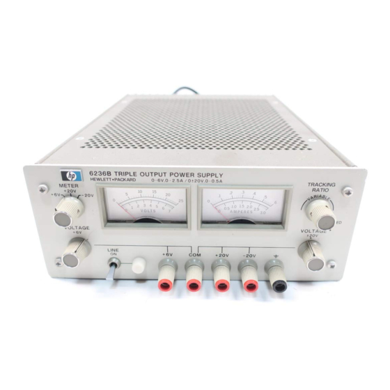
0.5 amps with an additional single output that in The front panel also contains a line switch and a the Model 6236B is rated at 0 to+6 volts and up to 2.5 pilot light, a voltmeter and an ammeter, and a meter... - Page 4 (S3) is set for the line voltage to be used. (See CAUTION notice in paragraph 3-2 for additional information.) Table 1-1. Specifications, Model 6236B and 6237B NOTE Model 6237 B 0 to +18V Output: Maximum rated output current is 1.0A.
-
Page 5: Instrument And Manual Identification
Packard field office (see the list at the rear of this manual power supply, starting with 00101. for addresses). Specify the model number, serial number prefix, and the HP Part Number provided on the title page. Table 1-1. Specifications, Models 6236B and 6237B (Continued) RESOLUTION:... -
Page 6: Section Ii Installation
SECTION II INSTALLATION INITIAL INSPECTION Before shipment, this instrument was inspected and found to be free of mechanical and electrical defects. As soon as the instrument is unpacked, inspect for any damage that may have occurred in transit. Save all packing materials until the inspection is completed. -
Page 7: Input Power Requirements
Figure 2-4 illustrates the standard configu- of this model operate from a 47-63 Hz single-phase line. rations of power cord plugs used by HP. Above each draw- ing is the HP option number for that configuration of power... -
Page 8: Section Iii Operating Instructions
The following steps describe the use of the Model 6236B or 6237B front panel controls and indicators illus- e. Set the ±20V VOLTAGE control for a 20-volt meter trated in Figure 3-1 and serve as a brief check that the sup- indication and short the +20V output terminal to the com- ply is operational. -
Page 9: Operation Beyond Rated Output
(see Figure 3-2). load and short-circuit protection circuit for the +6V output of the Model 6236B reduces the output current limit as the 2. Check the rating of the installed fuse and repla- output terminal voltage decreases. -
Page 10: Parallel Operation
A high-current output pulse may damage load components before the average output current is large enough to cause Figure 3-3. Current Limit Characteristics of the 6V Supply the current limiting circuit to operate. (Model 6236B) -
Page 11: Section Iv Principles Of Operation
+20-volt regulator. It has a fixed current By comparing its output to a high-stability refer- limit at 110% of its 1.0 amp output. ence, the 0 to +6-volt regulator (6236B) or 0 to +18- volt regulator (6237B) holds its output voltage at the 4-10 The reference and bias supply provides reference value determined by a front panel control. - Page 12 and returning control to the voltage comparison amplifier. with the voltage across R1. Since R2 is connected between the -6.2V reference supply and a point that feedback action 4-20 Turn-On/Turn-Off Control. When the power supply holds near -16mV, its current remains constant. This is turned on or off, Q15 in the turn-on control circuit with- current flows through R1 to produce a voltage drop across holds turn-on bias from Q1 while the regulator bias voltages...
- Page 13 -305mV potential on its non-inverting in- 4-26 0 To +6-Volt Regulator (Model 6236B) put. When this happens, the output of this amplifier goes positive and forward biases CR45. Since the current through...
- Page 14 4-39 Turn-On/Turn-Off Control Circuit values, paragraphs 4-15 through 4-21, which describe the voltage comparison amplifier, OR-gate, driver, series regu- lator, current limit circuit, turn-on control, and circuit 4-40 Immediately after the supply is energized and protection components of the +20-volt regulator circuit, until the output of the -12.4-volt regulator reaches about also apply to the +18-volt regulator.
-
Page 15: Test Equipment Required
----- Voltage Equipped with voltmeter Transformer accurate within 1 volt Oscilloscope Sensitivity: 100µV/cm. Display transient re- HP 180C with 1821A, Differential input. sponse and ripple and and 1801A or 1803A noise waveforms. plug-ins. Repetitive Rate: 60 Hz, 2µs Measure transient See Figure 5-5. -
Page 16: General Measurement Techniques
All instructions in this section apply to Models 5-11 Selecting Load Resistors. Power supply specifica- 6236B and 6237B unless otherwise indiated. tions are checked with a full load resistance connected 5-15 Rated Output, Tracking, Meter Accuracy, across the supply output. The resistance and wattage of... - Page 17 +18V supply should be 1.1 A performance test. ±5%. r. (Steps (r) through (t) apply to the 6236B only.) Rated Output and Ammeter Accuracy Connect the test setup shown in Figure 5-3 to the +6V f. Connect 40Ω 10W load resistors across both of the 20V output.
- Page 18 8.3 milliseconds (1/120 Hz) or 16.7 milliseconds (1/60 Hz). Since the fundamental ripple frequency present Figure 5-3. Output Current, Test Setup on the output of an HP supply is 120 Hz (due to full-wave rectification). an oscilloscope display showing a 120 Hz 5-19 Source Effect (Line Regulation) ∆...
- Page 19 an oscilloscope with sufficient bandwidth (20 MHz) must 5-24 Figure 5-4B shows a correct method of measuring be used. Ripple and noise measurements can be made at the output ripple of a constant voltage power supply any input ac line voltage combined with any dc output using a single-ended scope.
-
Page 20: Troubleshooting
current changes are to be achieved. Instead, a mercury- h. Adjust the sync controls separately for the positive wetted relay should be used for loading and unloading the and negative going transients so that not only the recovery supply. Connect it in the load switching circuit shown in waveshape but also as much as possible of the rise time of Figure 5-5. - Page 21 Table 5-2. Miscellaneous Troubles SYMPTOM CHECK - PROBABLE CAUSE High ripple a. Check operating setup for ground loops (see paragraph 5-22). b. Check main rectifiers (CR11, CR12, CR31, CR32, CR51, CR52) for open. c. Supply may be operating in current limit mode. Check current limit adjustment, paragraph 5-26, steps (l) thru (t).
- Page 22 RESPONSE NEXT ACTION Check output of +6V supply a. Normal a. If the output of this supply is normal (Model 6236B) unloaded but its voltage falls when or+18V supply loaded, check the current limit adjust (Model 6237B). ment, paragraph 5-16, steps (q) thru (t).
- Page 23 Table 5-5. +20V Supply Troubleshooting SYMPTOM STEP - ACTION RESPONSE - PROBABLE CAUSE High output voltage 1. Attempt to turn down a. If output voltage remains high, check Q1, Q15, (higher than rating) loop by shorting Q15 emitter- and CR9 for short. to-base b.
- Page 24 Table 5-6. -20V Supply Troubleshooting (Continued) SYMPTOM STEP - ACTION RESPONSE - PROBABLE CAUSE 3. Measure voltage at TP14. a. If TP14 is approx. -0.7V, check for open CR26 or defective U2. b. If TP14 is approx. +0.7V, check Z1 for open from pin 7 to 12 or for short from pin 6 to 12.
-
Page 25: Repair And Replacement
Notice that both the commercial and alternate re- 0002); for Options 220 or 240, use a normal time- placements listed in Table 6-4 apply only to the HP power constant 1-amp fuse (HP Part No. 2110-0001). supplies covered by this manual and their use in any other... -
Page 26: Meter Calibration
+6V (or +18V) output. Make the total resistance of R L current when a decreasing load resistance increases it to and the current sampling resistor 2.4 ohms (Model 6236B) 2.75A ±5%. or 18 ohms (6237B) to permit operating the supply at its 5-50 +18V Supply (Model 6237B). -
Page 27: Section Vi Replaceable Parts
SECTION VI REPLACEABLE PARTS Table 6-1. Reference Designators (Continued) INTRODUCTION = plug V = vacuum tube, This section contains information for ordering re- Q = transistor neon bulb, placement parts. Table 6-4 lists parts in alpha-numeric R = resistor photocell, etc. order by reference designators and provides the following S = switch VR = zener diode... - Page 28 Table 6-3. Code List of Manufacturers CODE MANUFACTURER ADDRESS CODE MANUFACTURER ADDRESS 01121 Allen Bradley Co. Milwaukee, WI 09353 C & K Components Inc. Newton, MA 02114 Ferroxcube Corp. Saugerties, NY 19701 Electra/Midland Corp. Mineral Wells, TX 02582 Clarostat Mfg. Co., Inc. Dover, NH 27014 National Semiconductor...
- Page 29 Diode, Si 1.5A 200V 1N4999 1901-0416 CR53, 54 6236B Not used 6237B Diode, Si 1A 200V 1N5059 1901-0327 CR55, 56 Diode, Si 1A 200V 1N5059 1901-0327 CR57 Diode, stabistor 150mA 15V STB523 03508 1901-0460 CR59 Diode, Si 1A 200V 1N5059 1901-0327 * 6236B/6237B...
- Page 30 01121 0686-5115 fxd, comp 10k 5% 1/2W EB1035 01121 0686-1035 var, 10k 02582 2100-3461 (VOLTAGE +6V or +18V) 6236B fxd, film 8.66k 1% 1/8W Type MF4C, T-9 19701 0698-8076 6237B fxd, film 2.87k 1% 1/8W Type MF4C-1 19701 0698-7631 fxd, ww 0.1 10% 3W...
- Page 31 Table 6-4. Replaceable Parts (Continued) REF. MFR. MFR. DESIG. DESCRIPTION PART NO. CODE PART NO. 6236B fxd, film 330 1% 1/8W Type MF4C, T-9 19701 0698-5663 6237B fxd, film 3.83k 1% 1/8W Type MF4C-1 19701 0698-3153 fxd, film 110k 1% 1/8W...
- Page 32 SJ1528 04713 1853-0063 Q3, 8 Power NPN Si 2N3055 (Note 1) 1854-0563 Circuit Board - Mechanical Heat Dissipator (CR51, 52, Q2, Q11 in 6236B; Q2 in 6237B) 207-CB 05820 1205-0033 Heat Sink (Q11) 28480 5000-6025 Spacer (for Q11 heatsink) 28480...
- Page 33 Delete R76, R77, and all references to the variable tracking ratio feature. CHANGE 2: Change potentiometers R1 and R41 to 10kΩ panel-mounted type, HP Part No. 2100-1854. CHANGE 3: Delete ferrite bead L3, 9170-0894, from the lead of diode CR49.
-
Page 34: Section Vii Circuit Diagrams
The component location diagram for power supply 6236B and 6237B. The test points (circled numbers) Models 6236B and 6237B is given below. The illustration shown on the schematic correspond to those on the shows the physical locations and reference designations component location diagram and in the troubleshooting of parts mounted on the printed circuit card. - Page 36 9-8- 77 Note 1: Change 1 applies to the following instruments from earlier production runs. Model 6236B: serial 1705A-00502, -505, -507, -526, -533, -534, -536, -541, -544, -546, -547, -573, -577, -594. Model 6237B: serial 1706A-00263, -264, -269, -272, -291, -296, -298, -299.
- Page 37 Artisan Technology Group is your source for quality new and certified-used/pre-owned equipment SERVICE CENTER REPAIRS WE BUY USED EQUIPMENT • FAST SHIPPING AND DELIVERY Experienced engineers and technicians on staff Sell your excess, underutilized, and idle used equipment at our full-service, in-house repair center We also offer credit for buy-backs and trade-ins •...