Advertisement
Table of Contents
September, 1984
New Information
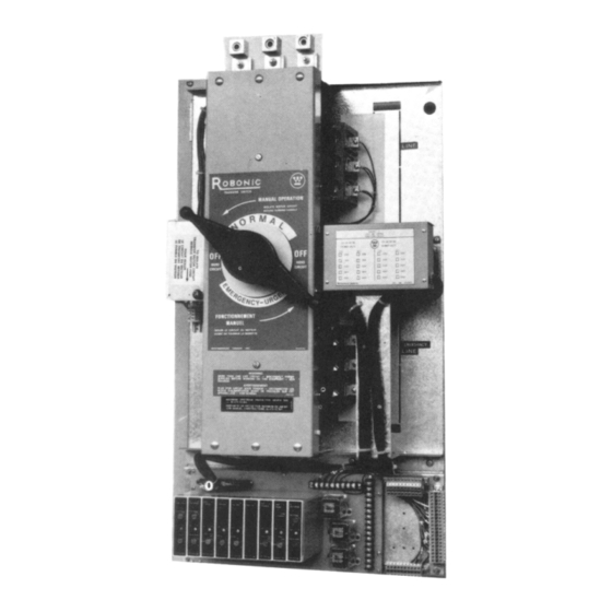
AUTOMATIC TRANSFER SWITCH
Westinghouse Canada
Electronics, Control and Distribution Products Division
Instruction Leaflet
30-471 (E)
Page 1
Robonic II Automatic
Transfer Switches
Operation and
Maintenance Manual
Index
Warranty ......................................... 2
Westinghouse Offices ..................... 3
General Description ........................ 4
Component Identification ................ 7
LRO Description ............................. 5
RO Description ............................... 6
PRO Description ............................. 6
Application Information ................... 7
Logic Control .................................. 7
Replacing Parts ............................ 13
Trouble Shooting Guide ................ 14
Recommended Maintenance ........ 14
Advertisement
Table of Contents

Related Manuals for Westinghouse 30-471 (E)


Summary of Contents for Westinghouse 30-471 (E)
-
Page 1: Table Of Contents
Robonic II Automatic Transfer Switches Operation and Maintenance Manual Index Warranty ... 2 Westinghouse Offices ... 3 General Description ... 4 Component Identification ... 7 LRO Description ... 5 RO Description ... 6 PRO Description ... 6 Application Information ... 7 Logic Control ... -
Page 2: Warranty
Instruction Leaflet 30-471 (E) Page 2 Warranty The company warrants the apparatus to be supplied hereunder to be of the kind designated or specified. The company shall repair or replace any defective part or parts, f.o.b. the company’s factory, repair shop or warehouse, which prove to be defective under normal and proper use within one year from the date of shipment, provided that the purchaser gives the Company immediate written notice of any... -
Page 3: Westinghouse Offices
London Ottawa Sarnia Sudbury Thunder Bay Toronto Windsor Winnipeg Westinghouse products for electrical utilities are available through the listed Utility Sales offices. Call the office nearest you. Utility Sales Offices Fredericton Halifax Montreal Toronto For Service Westinghouse Service Centres provide after-sales service, installation and start-up supervision,... -
Page 4: General Description
“Transfer switch, type B means an automatic transfer switch that (does) employ integral overcurrent protection”. Westinghouse Robonics in type A are equipped with special instantaneous magnetic only interrupter. The trip settings of these special interrupter are set (and fixed) at higher than standard values. -
Page 5: Lro Description
Solid State Logic Control Panel Type LRO Robonic II Automatic Transfer Switch Rated 30 amperes through 100 amperes at 600 volts Ac maximum 50 or 60 Hertz. The mechanism is a lever operated device controlled by a 120 volt unidirectional motor. The transfer motor drives a nylon cam which in turn operates a steel lever by sliding a pin along a slot in the back of the lever. -
Page 6: Ro Description
Instruction Leaflet 30-471 (E) Page 6 Type “RO” Robonic II Automatic Transfer Switch A complete line rated from 150 amperes through 1000 amperes at 600 volts Ac or at 250 volts Dc. The transfer mechanism consists of the transfer motor, a gear train and two breaker operating cams. -
Page 7: Component Identification
Table 1 — Interrupting, Closing and Withstand Rating — Robonic Type A Robonic rms symmetrical amperes Continuous Rating Type 600 Vac 30 to 100 amps 14,000 150 to 225 amps 22,000 300 to 1000 amps 22,000 1200 to 3000 amps 65,000 Since type A Robonics employ magnetic only breakers, their interrupt- ing, closing and withstand ratings are the same value. - Page 8 Instruction Leaflet 30-471 (E) Page 8 Both under and overfrequency cards are factory calibrated at 60 Hz. The actual values of pickup and dropout are as follows: Type Dial Setting Underfrequency Underfrequency Overfrequency Overfrequency Undervoltage / Underfrequency Module S#1288C58G01 Option# 5A, 26F Monitors one phase of power source.
- Page 9 Adjustments Timer and frequency modules can be adjusted as per module front plate. Voltage sensing modules can be adjusted as follows: Undervoltage Module Description Set Dropout knob maximum Counter-clockwise Set pick-up knob maximum Counter-clockwise Increase line volts to desired Dropout value (normally 70%) LED should be “ON”...
- Page 10 Instruction Leaflet 30-471 (E) Page 10 This time delay relay is an octual plug-in, sychronous motor type. It is complete with clutch and mechanical load switch giving one instantane- ously operated normally open contact and a timed single pole double throw contact in a dust-tight grey capsule.
- Page 11 It may be used to start an engine-generator set at selected intervals, at least once per week, but without causing the transfer switch to operate and transfer the load to the generator supply. At the end of the interval it will cause the engine-generator to shutdown.
- Page 12 Instruction Leaflet 30-471 (E) Page 12 Schematic of Robonic II Transfer Switch Consider the Robonic II in the normal operating position, with normal power available and the normal interrupter closed. The following are energized: U.V. (undervoltage module), TDES (time delay engine start), and NR (normal relay).
-
Page 13: Replacing Parts
Replacing Parts The Robonic Automatic Transfer Switch has been designed to have all components accessible and readily removable from the front of the panels. The Robonic Transfer Switch is divided into two basic sections. The upper section consists of the main contacts and transfer mechanism, the lower section consisting of all the automatic control devices. -
Page 14: Trouble Shooting Guide
Instruction Leaflet 30-471 (E) Page 14 Trouble Shooting Guide Symptoms Possible Causes • refusal to re-transfer to normal • a voltage sensing relay did not source upon restoration energize • emergency to normal time delay relay has failed • a loose control connection •...