Table of Contents
Advertisement
Quick Links
Total Access
CONTENTS
1. GENERAL ................................................................... 1
2. INSTALLATION .......................................................... 2
3. OPTIONS ..................................................................... 2
4. TESTING ..................................................................... 5
5. SPECIFICATIONS ....................................................... 6
6. MAINTENANCE ......................................................... 6
7. WARRANTY AND CUSTOMER SERVICE .............. 7
Figures
Figure 1. Total Access 750 BCU, List 2 ............................. 1
Figure 2. Time Slot Usage .................................................. 4
Figure 3. Bantam Jack Monitoring Points .......................... 6
Figure 4. DB-9 Connector Pinout ....................................... 6
Tables
Table 1. Compliance Codes ............................................... 2
Table 2. DIP Switch S1 Options ......................................... 3
Table 3. Pinout Connectors for RJ-48 TI Interface ............ 5
Table 4. Pinout Connectors for RJ-48 FTI Interface .......... 5
Table 5. LED Indication ...................................................... 5
Table 6. Specifications ....................................................... 8
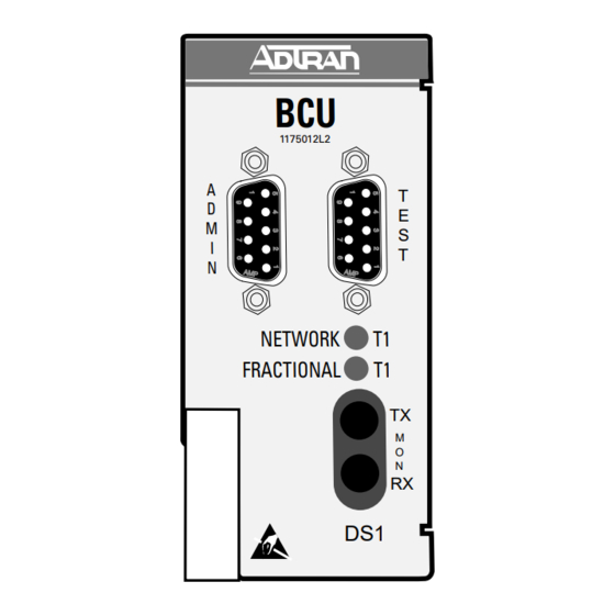
1. GENERAL
This practice provides installation and operation
procedures for the ADTRAN Total Access
Bank Controller Unit (BCU) common module, List 2.
The BCU L2 adds the capability to support Fractional
T1 operation via a DSX-1 interface port (RJ-48) on
the rear of the TA 750 Chassis. This port is
commonly used to interface with PBX equipment.
The TA 750 BCU L2 module is designed specifically
for the ADTRAN Total Access 750 and is not used in
any other product. Figure 1 is an illustration of the
TA 750 BCU.
Revision History
This document has been revised to include Windows
Hyperterminal PASSWORD information, and update
Switch settings.
Features
The TA 750 BCU, P/N 1175012L2, includes the
following features:
•
Controls all common equipment and access
modules.
Trademarks: Any brand names and product names included in this document are
61175012L2-5D
Bank Controller Unit with Fractional T1 (DSX-1)
TM
TA 750 BCU with Fractional T1 (DSX-1)
Installation and Maintenance
750
TM
Section 61175012L2-5, Issue 4
trademarks, registered trademarks, or trade names of their respective holders.
CLEI Code: SIUXJKBB_ _
Figure 1. Total Access 750 BCU, List 2
•
Supports DSX-1 short haul T1 interface.
•
T1 network termination.
•
Built-in Channel Service Unit (CSU).
•
Provides VT 100 craft interface via faceplate
DB-9 connector.
•
Bantam Jacks provide access to Network T1.
•
LED network status indication.
•
T1 performance monitoring.
•
Supports TR-08 signaling.
•
UL 1950 compliant.
•
Meets NEBS Level 3 requirements.
General Description
The TA 750 BCU L2 is a common module plug-in
unit designed for the TA 750. The BCU, with a built-
in CSU, provides all control functions for the TA 750
common units and all individual access modules. A
faceplate ADMIN DB-9 provides access for a VT100
terminal for screen menu provisioning, and bantam
test jacks provide, transmit, and receive monitoring.
An additional TEST DB-9 provides timing for DS0
test equipment. Faceplate LEDs show status
information for the network and Fractional (DSX-1)
T1. The unit is comprised of a main circuit board and
Section 61175012L2-5D
Issue 4, July 2000
T
E
S
T
TX
M
O
N
RX
DS1
1
Advertisement
Table of Contents

Related Manuals for ADTRAN Total Access 750 BCU DSX-1


Summary of Contents for ADTRAN Total Access 750 BCU DSX-1
-
Page 1: Table Of Contents
The TA 750 BCU L2 module is designed specifically • UL 1950 compliant. for the ADTRAN Total Access 750 and is not used in • Meets NEBS Level 3 requirements. any other product. Figure 1 is an illustration of the TA 750 BCU. -
Page 2: Installation
Fractional T1 Changes or modifications not expressly approved by (DSX-1) interface. ADTRAN could void the user's authority to operate this equipment. DIP switch S1 must be provisioned while the BCU is withdrawn from the chassis. Once installed, any... -
Page 3: Table 2. Dip Switch S1 Options
Table 2. DIP Switch S1 Options Switch Function Description S1-1 S1-3 Setting S1-1 .... Framing Format ESF* S1-3 .... TR-08 Signaling TR-08 Digroup A TR-08 Digroup B, C, or D S1-2 .... Line Code Format ..Enables Bipolar Eight-Zero Substitution (B8ZS) which allows for Clear Channel operation for the T1 carrier system, or Alternate Mark Inversion (AMI). -
Page 4: Figure 2. Time Slot Usage
1. Select Bank Controller (1), Provisioning (2), NOTE FT1 (2), FT1 Channels (4) If a timeslot is assigned to the Fractional T1 2. Figure 2 shows the current time slots in use by (DSX-1) port and an access module is inserted the TA 750. -
Page 5: Testing
Table 5. LED Indication Table 3. Pinout Connectors for RJ-48 TI Interface : f f . r e i t c . t s Faceplate Bantam Jack The faceplate bantam jack provides a means to monitor the network T1 connected to the rear of the TA 750 chassis. -
Page 6: Specifications
(such as maintenance for design operation. Hyperterminal) require that the current session ADTRAN does not recommend that repairs be be disconnected and reconnected after changing attempted in the field. Repair services are obtained by from one baud rate to another. -
Page 7: Warranty And Customer Service
7. WARRANTY AND CUSTOMER SERVICE ADTRAN will replace or repair this product within 10 years from the date of shipment if it does not meet its published specifications or fails while in service (see: ADTRAN Carrier Networks Equipment Warranty, Repair, and Return Policy and Procedure, document: 60000087-10A). -
Page 8: Table 6. Specifications
Table 6. Specifications : e t s t i , r a : e t z i l : l a : e t t i c & & s t r " 6 " 3 " 0 . b l i t a º...