Table of Contents
Advertisement
Advertisement
Table of Contents

Summary of Contents for Exmark SD270SB20
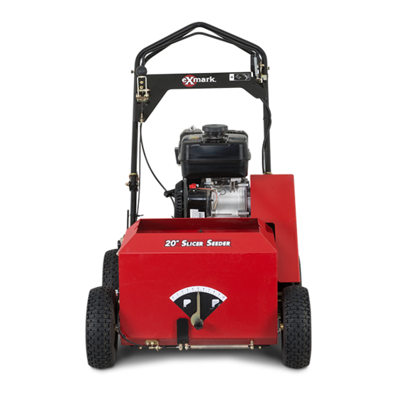
- Page 1 SLICER SEEDER For Serial Nos. 313,652,088 & Higher Part No. 4501-674 Rev. A...
- Page 2 Replacements may be ordered through the engine manufacturer. Exmark reserves the right to make changes or add improvements to its products at any time without incurring any obligation to make such changes to products manufactured previously.
-
Page 3: Introduction
Introduction CONGRATULATIONS on the purchase of your Exmark Slicer Seeder. This product has been carefully designed and manufactured to give you a maximum amount of dependability and years of trouble-free operation. This manual contains operating, maintenance, adjustment, and safety instructions for your Exmark Slicer Seeder. -
Page 4: Table Of Contents
Contents Introduction ............3 Safety ..............5 Safety Alert Symbol ......... 5 Safe Operating Practices ........5 Safety and Instructional Decals ....... 9 Specifications ............13 Model Numbers ..........13 Systems ............13 Dimensions............13 Torque Requirements ........13 Setup ..............14 Setup the Handle ..........14 Product Overview ..........14 Operation ..............15 Controls ............15... -
Page 5: Safety
Indicates an imminently hazardous situation which, if safely perform the job. Only use accessories and not avoided, Will result in death or serious injury. attachments approved by Exmark. WARNING: Black lettering / Orange background. • Wear appropriate clothing including safety glasses, Indicates a potentially hazardous situation which, if substantial footwear, and hearing protection. - Page 6 Safety DANGER DANGER In certain conditions gasoline is extremely In certain conditions during fueling, static flammable and vapors are explosive. electricity can be released causing a spark which can ignite gasoline vapors. A fire or A fire or explosion from gasoline can burn explosion from gasoline can burn you and you, others, and cause property damage.
- Page 7 Safety Operation – Before clearing blockages. – Whenever you leave the machine. WARNING • Stop engine, wait for all moving parts to stop: Operating engine parts, especially the muffler, – Before refueling. become extremely hot. Severe burns can occur on contact and debris, such as leaves, grass, –...
- Page 8 Tall grass can Unauthorized modifications to the original hide obstacles. equipment or failure to use original Exmark • Watch for ditches, holes, rocks, dips and rises that parts could lead to serious injury or death.
-
Page 9: Safety And Instructional Decals
Exmark equipment dealer or labels. distributor or from Exmark Mfg. Co. Inc. • Replace all worn, damaged, or missing safety • Safety signs may be affixed by peeling off the signs. - Page 10 Safety 116-9985 1. Read and understand 3. AC terminal - orange the operator’s manual wire connects to engine before servicing this harness 121-6203 machine. 2. Positive terminal - red 4. Negative terminal - black 1. Bypass lever position for 3. Read the Operator’s and blue wires wire operating the machine...
- Page 11 Safety 116-8648 1. To start the engine, read the Operator’s manual - (1) Park 3. Cutting blades - release the blade control bail (neutral the machine on a level surface (2) Fill the engine with oil position) to disengage the cutting blades; hold the blade (3) Move the control bars to a neutral position (4) Start control bail against the handle to engage the cutting the engine.
- Page 12 Safety 116-8537...
-
Page 13: Specifications
• Engine Specifications: See your Engine Owner’s Tread Turf TL Manual Size 11 x 4.0-4 • Engine Oil Type: Exmark 4–Cycle Premium Ply Rating Engine Oil Pressure 13 psi • RPM: Full Speed: 3800 ±100 RPM (No Load) (90 kPa) -
Page 14: Setup
Product Overview Setup Product Overview Setup the Handle 1. Raise the handle to the operating position. Figure 4 1. Seeder control lever 6. Seed hopper 2. Drive bail 7. Seeding rate gauge G016884 3. Handle 8. Depth control lever 4. Blade control bail 9. -
Page 15: Operation
Operation Operation on the distance between the bail and the handle. When the bail is released, the unit will stop moving. Note: Determine the left and right sides of the machine from the normal operating position. Controls Choke Control Located on the engine. The choke is used to aid in starting a cold engine. -
Page 16: Pre-Start
Operation Note: The last notch on the handle does not latch Push the lever forward to start the seed flow and pull it rearward to stop the seed flow. on the slot. To release the drive wheels, pull up on the handle, Park Brake Lever pull it out until the last notch engages in the slot. - Page 17 Operation 2. On the front RH side of the engine, rotate the engine on/off switch clockwise to the “ON” position. 3. On the rear RH side of the engine, move the choke lever rearward to the “ON” position. On a warm engine, leave the choke in the “OFF” position.
- Page 18 Operation Note: If the unit creeps forward or rearward DANGER when the drive bail is in the neutral position, stop When the machine is in operation, contact with the engine and adjust the self-propel drive cable rotating or moving parts will severely injure (see Adjusting the Self-Propel Drive in the hands and feet.
-
Page 19: Operating Tips
Operation Adjusting the Cutting Blade Depth 1. Bring the unit to a full stop. 2. Disengage the cutting blades. 3. Stop the engine and wait for all moving parts to stop before leaving the operating position. Disconnect the wire from the spark plug. 4. -
Page 20: Transporting
Operation engine to bog down, raise the blades a bit and make a few passes before lowering them to the full depth. Transporting Transporting a Unit WARNING Loading the machine onto a trailer without strong enough or properly supported ramps could be dangerous. -
Page 21: Maintenance
Maintenance Maintenance Note: Determine the left and right sides of the machine from the normal operating position. WARNING WARNING If you leave the wire on the spark plug, someone Tipping the machine may cause the fuel to leak could accidentally start the engine. Accidental from the carburetor or the fuel tank. -
Page 22: Periodic Maintenance
If it make a grinding noise and is halting, oil fill cap, remove cap and fill to the “FULL” the bearings are worn; replace them when the mark on the dipstick. Exmark 4-Cycle Premium blades are replaced. Engine Oil is recommended; refer to the Engine 8. -
Page 23: Check For Loose Hardware
WARNING serious personal injury or death. Oil may be hot after engine has been run. Always install the original Exmark blades, Contact with hot oil can cause severe personal blade drivers, and blade bolts as shown. injury. -
Page 24: Check Condition Of Belts
Maintenance 2. Stop engine, wait for all moving parts to stop, and remove spark plug wire. Engage parking brake. 3. Place a suitable drain pan under the oil drain and remove the oil drain plug. 4. After the oil has drained, replace the plug. 5. -
Page 25: Change Hydraulic Transmission Filters And Fluid
1/2–1 1/4 inches (13–32 mm) below the top of the fill port. Thread Locking Adhesives Exmark Premium Hydro Oil is recommended. Thread locking adhesives such as “Loctite 242” Mobil 1 15W50 is an acceptable alternative. or “Fel-Pro, Pro-Lock Nut Type” are used on the 9. -
Page 26: Adjustments
Maintenance Adjustments 2. Disconnect the wire from the spark plug. 3. Close the fuel valve. Note: Shut off engine, wait for all moving parts to 4. Disconnect the fuel line by loosening the tube stop, and remove spark plug wire before servicing, clamp at the carburetor. -
Page 27: Adjusting The Self-Propel Drive Belt Tension
Maintenance g016901 Figure 14 Figure 15 1. Top/Bottom adjustment 4. Turnbuckle nuts 2. Cable 5. Self-propel drive bail 5. To tighten the belt, loosen the four mounting 3. Jam nut nuts/bolts securing the pulley carriage to the frame and move the carriage to the left, tightening the belt, then secure the four mounting nuts and •... -
Page 28: Cleaning
Maintenance Cleaning 2. Raise the cutting blades to the highest position. 3. Pull the seeder control lever to the Off position. Clean Engine and Exhaust 4. Loosen the nuts on the seed gate control cable (see Figure 17). System Area Service Interval: Before each use or daily (May be required more often in dry or dirty... -
Page 29: Cleaning Under The Belt Cover
Maintenance Waste Disposal Note: It will take two people to tip the machine rearward safely. 5. Remove the debris with a hardwood scraper. Motor Oil Disposal Avoid burrs and sharp edges. Engine oil is a pollutant to the environment. Dispose 6. -
Page 30: Troubleshooting
Troubleshooting Troubleshooting Important: It is essential that all operator safety mechanisms be connected and in proper operating condition prior to use. When a problem occurs, do not overlook the simple causes. For example: starting problems could be caused by an empty fuel tank. The following table lists some of the common causes of trouble. - Page 31 No Claim of breach of warranty shall be cause for cancellation provided by Exmark. or rescission of the contract of sale of any Exmark mower. There are no other express warranties except for engine and All implied warranties of merchantability (that the special emission system coverage.
- Page 32 Notes:...
- Page 33 Notes:...
- Page 34 Service Record Date: Description of Work Done: Service Done By:...
- Page 36 Label Here (Included in the Literature Pack) or Fill in Below Engine Model No. and Spec. No. Model No. Engine Serial No. (E/No) Serial No. ©2013 Exmark Mfg. Co., Inc. Part No. 4501-674 Rev. A 2101 Ashland Ave (402) 223-6300 *4501-674* A Beatrice, NE 68310...