Table of Contents
Advertisement
Copyright
This publication, including all photographs, illustrations and software, is protected
under international copyright laws, with all rights reserved. Neither this manual, nor
any of the material contained herein, may be reproduced without written consent of
the author.
Version 1.0
Disclaimer
The information in this document is subject to change without notice. The manufac-
turer makes no representations or warranties with respect to the contents hereof and
specifically disclaims any implied warranties of merchantability or fitness for any
particular purpose. The manufacturer reserves the right to revise this publication and
to make changes from time to time in the content hereof without obligation of the
manufacturer to notify any person of such revision or changes.
Trademark Recognition
Microsoft, MS-DOS and Windows are registered trademarks of Microsoft Corp.
MMX, Pentium, Pentium-II, Pentium-III, Celeron are registered trademarks of Intel
Corporation.
Other product names used in this manual are the properties of their respective
owners and are acknowledged.
Federal Communications Commission (FCC)
This equipment has been tested and found to comply with the limits for a Class B
digital device, pursuant to Part 15 of the FCC Rules. These limits are designed to
provide reasonable protection against harmful interference in a residential installa-
tion. This equipment generates, uses, and can radiate radio frequency energy and, if
not installed and used in accordance with the instructions, may cause harmful inter-
ference to radio communications. However, there is no guarantee that interference
will not occur in a particular installation. If this equipment does cause harmful
interference to radio or television reception, which can be determined by turning the
equipment off and on, the user is encouraged to try to correct the interference by one
or more of the following measures:
•
Reorient or relocate the receiving antenna
•
Increase the separation between the equipment and the receiver
•
Connect the equipment onto an outlet on a circuit different from that to
which the receiver is connected
•
Consult the dealer or an experienced radio/TV technician for help
Shielded interconnect cables and a shielded AC power cable must be employed with
this equipment to ensure compliance with the pertinent RF emission limits governing
this device. Changes or modifications not expressly approved by the system's manu-
facturer could void the user's authority to operate the equipment.
Preface
Preface
Advertisement
Table of Contents
Troubleshooting

Related Manuals for ECS X79R-AX


Summary of Contents for ECS X79R-AX
- Page 1 Preface Copyright This publication, including all photographs, illustrations and software, is protected under international copyright laws, with all rights reserved. Neither this manual, nor any of the material contained herein, may be reproduced without written consent of the author. Version 1.0 Disclaimer The information in this document is subject to change without notice.
- Page 2 Declaration of Conformity This device complies with part 15 of the FCC rules. Operation is subject to the following conditions: • This device may not cause harmful interference, and • This device must accept any interference received, including interfer- ence that may cause undesired operation Canadian Department of Communications This class B digital apparatus meets all requirements of the Canadian Interference- causing Equipment Regulations.
-
Page 3: Table Of Contents
Preface Chapter 1 Introducing the Motherboard Introduction..................1 Feature....................2 Specifications..................4 Motherboard Components (X79R-AX)........7 Motherboard Components (X79R-AX Deluxe)......9 Chapter 2 11 11 11 11 11 Installing the Motherboard Safety Precautions................11 Choosing a Computer Case............11 Installing the Motherboard in a Case..........11 Checking Jumper Settings.............12 Setting Jumpers..............12... - Page 4 M.I.B. X (MB Intelligent BIOS X ) Menu.......49 Boot Menu .............55 ......Security Menu ...............60 Save & Exit Menu..............61 Updating the BIOS..............63 Chapter 4 Using the Motherboard Software About the Software DVD-ROM/CD-ROM.........65 Auto-installing under Windows XP/Vista/7.......65 Running Setup................66 Manual Installation................68 Utility Software Reference............68 Chapter 5 ®...
-
Page 5: Introducing The Motherboard
USB 3.0 ports, one Buletooth Dongle, one Wireless LAN Dongle, one optical SPDIFO port and audio jacks for microphone, line-in and 8-ch line-out. *1. ECS M.I.B X stands for extreme O.C BIOS interface. Please refer to chapter 3 for detailed setup information. -
Page 6: Feature
6Gb/s Host Controllers • Two Ti Chips, Ti TUSB7340 supports the four USB 3.0 ports at the rear I/O, Ti TUSB7320 supports the Front USB 3.0 header (two ports) *2.Only the X79R-AX has these chips. Memory • Supports DDR3 2400(OC)/2133(OC)/1866(OC)/1600/1333/1066 DDR3 SDRAM with four-channel architecture •... - Page 7 Wake-on-LAN and remote wake-up support Integrated I/O The motherboard has a full set of I/O ports and connectors: • Two RJ45 LAN ports (Only X79R-AX has two ports) • Two eSATA 6Gb/s ports (Only X79R-AX has these ports) • One CLR_CMOS button (Only X79R-AX has this button) •...
-
Page 8: Specifications
- 2 x eSATA 6Gb/s ports supporting external SATA 6Gb/ s devices *1.If you want to know more about the four gray SAS6G1-2/ 3-4 ports near the white SATA ports, please refer to the ECS website. *2.Only the X79R-AX has these chips. - Page 9 1 x PS/2 keyboard/mouse combo port Rear Panel I/O • 1 x CLR_CMOS button (Only X79R-AX has this button) • 2 x eSATA 6Gb/s ports (Only X79R-AX has these ports) • 6 x USB 2.0 ports • 4 x USB 3.0 ports •...
- Page 10 System BIOS • AMI BIOS with 64Mb SPI Flash ROM • Supports Plug and Play 1.0A, DMI • Supports ACPI revision 1.0 specification • Supports S1/STR(S3)/STD(S4) • Supports Hardware monitor • Audio, LAN, USB 3.0, eSATA, Bluetooth and Wireless LAN can be disabled in BIOS •...
-
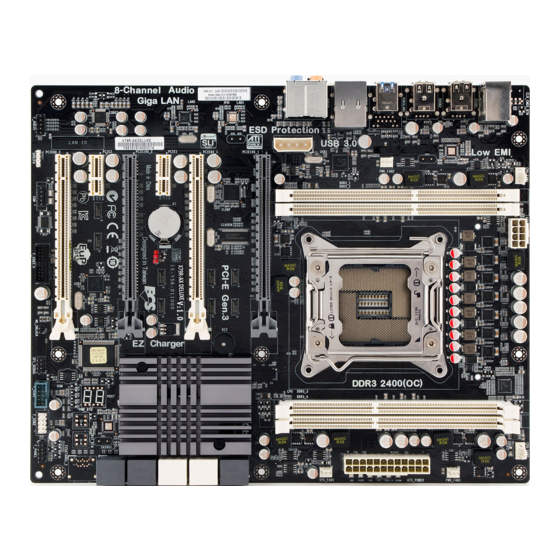
Page 11: Motherboard Components (X79R-Ax)
Motherboard Components (X79R-AX) Introducing the Motherboard... - Page 12 Table of Motherboard Components LABEL COMPONENTS ® 1. CPU Socket Intel Sandy Bridge-E processor in the LGA2011 package 2. DDR3_3~4 240-pin DDR3 SDRAM slots 3. CPU_FAN2 CPU cooling fan connector 4. PWR_FAN1 Power cooling fan connector 5. ATX_POWER Standard 24-pin ATX power connector 6.
-
Page 13: Motherboard Components (X79R-Ax Deluxe)
Motherboard Components (X79R-AX Deluxe) Introducing the Motherboard... - Page 14 Table of Motherboard Components LABEL COMPONENTS ® 1. CPU Socket Intel Sandy Bridge-E processor in the LGA2011 package 2. DDR3_3~4 240-pin DDR3 SDRAM slots 3. CPU_FAN2 CPU cooling fan connector 4. PWR_FAN1 Power cooling fan connector 5. ATX_POWER Standard 24-pin ATX power connector 6.
-
Page 15: Installing The Motherboard
Chapter 2 Installing the Motherboard Safety Precautions • Follow these safety precautions when installing the motherboard • Wear a grounding strap attached to a grounded device to avoid dam- age from static electricity • Discharge static electricity by touching the metal case of a safely grounded object before working on the motherboard •... -
Page 16: Checking Jumper Settings
Do not over-tighten the screws as this can stress the motherboard. Checking Jumper Settings This section explains how to set jumpers for correct configuration of the motherboard. Setting Jumpers Use the motherboard jumpers to set system configuration options. Jumpers with more than one pin are numbered. -
Page 17: Checking Jumper Settings
Checking Jumper Settings The following illustration shows the location of the motherboard jumpers. Pin 1 is labeled. Jumper Settings Type Jumper Description Setting (default) 1-2: NORMAL 2-3: CLEAR CMOS CLR_CMOS 3-pin Clear CMOS CLR_CMOS Before clearing the CMOS, make sure to turn off the system. -
Page 18: Installing Hardware
Installing Hardware Installing the Processor Caution: When installing a CPU heatsink and cooling fan make sure that you DO NOT scratch the motherboard or any of the surface-mount resis- tors with the clip of the cooling fan. If the clip of the cooling fan scrapes across the motherboard, you may cause serious damage to the motherboard or its components. - Page 19 CPU Installation Procedure The following illustration shows CPU installation components. A. Disengaging of the Load Lever · Press the hook of lever (with open 1 signal) to clear retention tab. · Press the hook of another lever (with close 1 signal) to clear another retention tab.
-
Page 20: Installing Memory Modules
1. To achieve better airflow rates and heat dissipation, we suggest that you use a high quality fan with 3800 rpm at least. CPU fan and heatsink installation procedures may vary with the type of CPU fan/ heatsink supplied. The form and size of fan/heatsink may also vary. 2. - Page 21 1.There is no limitation about how to install the DIMMs into the slots in X79, but for best performance and compatibility, we recommend that users install the DIMMs as the above table shows. 2.We suggest users not mix memory type. It is recommended to use the same brand and type memory on this motherboard.
-
Page 22: Expansion Slots
Expansion Slots Installing Add-on Cards The slots on this motherboard are designed to hold expansion cards and connect them to the system bus. Expansion slots are a means of adding or enhancing the motherboard’s features and capabilities. With these efficient facilities, you can in- crease the motherboard’s capabilities by adding hardware that performs tasks that are not part of the basic system. - Page 23 Follow these instructions to install an add-on card: Remove a blanking plate from the system case corresponding to the slot you are going to use. Install the edge connector of the add-on card into the expansion slot. Ensure that the edge connector is correctly seated in the slot. Secure the metal bracket of the card to the system case with a screw.
-
Page 24: Connecting Optional Devices
Connecting Optional Devices Refer to the following for information on connecting the motherboard’s optional devices: F_AUDIO: Front Panel Audio Header The front panel audio header allows the user to install auxiliary front-oriented microphone and line-out ports for easier access. This header supports HD audio by default. - Page 25 For AC’97 HD Front Audio Description Description Front panel microphone input signal Analog ground Microphone power 4 Analog power( +5V ) Right channel to front panel 6 Right channel return from front panel RSVD No pin Left channel to front panel 10 Left channel return from front panel AC’...
- Page 26 If you use AC’ 97 Front Panel, please don’ t tick off “ Using Front Jack Detect ” If you use HD Audio Front Panel, please tick off the option of “ Using Front Jack Detect ” . *For reference only SATA3G1_2 &...
- Page 27 EXSATA6G1_2: Serial ATA III connector (Only the X79R-AX has this connector) This connector is used to support the external Serial ATA devices for the highest data transfer rates (6Gb/s), simpler disk drive cabling and easier PC assembly. It doubles the transfer rate of current SATA 3Gb/s interface.
- Page 28 USB3F: Front Panel USB 3.0 header This Motherboard implements one USB 3.0 header supporting 2 extra front USB 3.0 ports, which delivers 5Gb/s transfer rate. Signal Name Signal Name USB POWER SSRX0+ SSRX0- SSTX0- SSTX0+ SSTX1+ SSTX1- SSRX1+ SSRX1- USB POWER SPDIFO: SPDIF out header This is an optional header that provides an SPDIFO (Sony/Philips Digital Interface) output to digital multimedia device through optical fiber or coaxial connector.
- Page 29 ME_UNLOCK: ME Unlock Header Pin 1-2 Function Short Unlock Open Lock Installing the Motherboard...
-
Page 30: Installing Sata Hard Drives
Installing SATA Hard Drives This section describes how to install SATA hard drives. About SATA Connectors Your motherboard features four SATA 3Gb/s connectors, two EXSATA 6Gb/s connec- tors and six SATA 6Gb/s connectors supporting a total of twelve drives. SATA refers to Serial ATA (Advanced Technology Attachment) is the standard interface for the IDE hard drives which are currently used in most PCs. -
Page 31: Connecting I/O Devices
Connecting I/O Devices The backpanel of the motherboard may has either of the following two I/O ports, please take the actual motherboard for detailed parts. PS/2 Keyboard/Mouse Connect the PS/2 Keyboard or PS/2 Mouse to the PS/2 Combo Port combo port. Use the CLR_CMOS button to clear CMOS. - Page 32 PS/2 Keyboard/Mouse Connect the PS/2 Keyboard or PS/2 Mouse to the PS/2 Combo Port combo port. Connect an RJ-45 jack to the LAN port to connect your LAN Port computer to the Network. USB 2.0 Ports Use the USB 2.0 ports to connect USB 2.0 devices. This jack connects to external optical digital audio out- Optical SPDIF Output put devices.
-
Page 33: Connecting Case Components
Connecting Case Components After you have installed the motherboard into a case, you can begin connecting the motherboard components. Refer to the following: Connect the CPU cooling fan cable to CPU_FAN1/2. Connect the system cooling fan connector to SYS_FAN1. Connect the power cooling fan connector to PWR_FAN1/2. Connect the case switches and indicator LEDs to the F_PANEL. - Page 34 2. Connecting 8/4-pin power cable Users please note that the 8-pin and 4-pin power cables can both be con- nected to the ATX12V connector. When installing 8-pin power cable, the latches of power cable and the ATX12V connector match perfectly. 8-pin power cable When installing 4-pin power cable, the latch falls on the left side of the ATX12V connec-...
- Page 35 ATX_ POWER: ATX 24-pin Power Connector Signal Name Signal Name +3.3V +3.3V +3.3V -12V Ground Ground PS_ON Ground Ground Ground Ground Ground PWRGD +5VSB +12V +12V +3.3V Ground PWR_FAN1/2: FAN Power Connectors Signal Name Function System Ground Power +12V +12V Sense Sensor ATX12V: ATX 12V Power Connector...
-
Page 36: Front Panel Header
Front Panel Header The front panel header (F_PANEL) provides a standard set of switch and LED headers commonly found on ATX or Micro ATX cases. Refer to the table below for information: Signal Function Signal Function HD_LED_P Hard disk LED(+) 2 FP PWR/SLP *MSG LED(+) HD_LED_N Hard disk LED(- ) FP PWR/SLP *MSG LED(-) -
Page 37: Using Bios
Chapter 3 Using BIOS About the Setup Utility The computer uses the latest “American Megatrends Inc. ” BIOS with support for Windows Plug and Play. The CMOS chip on the motherboard contains the ROM setup instructions for configuring the motherboard BIOS. The BIOS (Basic Input and Output System) Setup Utility displays the system’s configuration status and provides you with options to set system parameters. -
Page 38: Resetting The Default Cmos Values
Press the delete key to access BIOS Setup Utility. Resetting the Default CMOS Values When powering on for the first time, the POST screen may show a “CMOS Settings Wrong” message. This standard message will appear following a clear CMOS data at factory by the manufacturer. You simply need to Load Default Settings to reset the default CMOS values. - Page 39 In this manual, default values are enclosed in parenthesis. Submenu items are denoted by a icon . The default BIOS setting for this motherboard apply for most conditions with optimum performance. We do not suggest users change the default values in the BIOS setup and take no responsibility to any damage caused by changing the BIOS settings.
-
Page 40: Main Menu
Advanced Select the advanced icon and press <Enter> or double click the left key of the mouse to display the the following screen. Main Menu This menu shows the information of BIOS and enables you to set the system language, date and time. Main Advanced Chipset... -
Page 41: Advanced Menu
Advanced Menu The Advanced menu items allow you to change the settings for the CPU and other system. Main Advanced Chipset M.I.B.X Boot Security Save & Exit Legacy OpROM Support Enabled/Disabled Onboard Launch PXE OpROM Disabled LAN Option ROM EXSATA Controller Mode AHCI Mode eSATA Controller Mode AHCI Mode... - Page 42 Use this item to enable or disable the Onboard LAN 1. Onboard LAN 2 Controller (Enabled) Use this item to enable or disable the Onboard LAN 2. Only the X79R-AX has this item. Press <Esc> to return to the Advanced Menu page.
- Page 43 PC Health Status On motherboards support hardware monitoring, this item lets you monitor the paeameters for critical voltages, temperatures and fan speeds. Main Advanced Chipset M.I.B. X Boot Security Save & Exit PC Health Status Smart Fan Function System Temperature 49°C CPU Fan1 Speed 0 RPM...
- Page 44 CPU/SYS Fan 1/2 Smart Fan Mode (Normal) These items allow you to select the CPU/System Fan 1/2 Smart Fan mode. Smart Fan Start PWM value (180) This item is used to set the start PWM value of the smart fan. Smart Fan Start PWM TEMP(-) (30) This item is used to set the start PWM temperature of the smart fan.
- Page 45 Power Management Setup This page sets up some parameters for system power management operation. Main Advanced Chipset M.I.B. X Boot Security Save & Exit Power Management Setup About Resume by Ring Resume By Ring Disabled Resume By PME Disabled Resume By USB (S3) Disabled Resume By PS2 KB (S3) Disabled...
- Page 46 ACPI Configuration The item in the menu shows the highest ACPI sleep state when the system enters suspend. Aptio Setup Utility - Copyright (C) 2011 American Megatrends, Inc. Main Advanced Chipset M.I.B. X Boot Security Save & Exit ACPI Settings Select the highest ACPI sleep state the system ACPI Sleep State...
- Page 47 SATA Configuration Use this item to show the mode of serial ATA configuration options. Main Advanced Chipset M.I.B. X Boot Security Save & Exit SATA Configuration (1) IDE Mode. (2) AHCI Mode. (3) RAID Mode. SATA Mode AHCI Mode Aggressive Link Power Management Enabled SATA Port1 Not Present...
- Page 48 SCU SATA 6Gb/s Configuration Use this item to show the information of SCU SATA 6Gb/s configuration. Legacy USB Support (Enabled) Use this item to enable or disable support for legacy USB devices. Setting to Audio Main Advanced Chipset M.I.B. X Boot Security Save &...
- Page 49 All USB Devices (Enabled) Use this item to enable or disable all USB devices. OnChip USB 3.0 Controller (Enabled) Use this item to enable or disable the onchip USB 3.0 controller. Legacy USB Support (Enabled) Use this item to enable or disable support for legacy USB devices. Setting to Audio allows the system to detect the presence of the USB device at startup.
- Page 50 Serial Port 0 Configuration Scroll to this item and press <Enter> to view the following screen: Main Advanced Chipset M.I.B. X Boot Security Save & Exit Enabled or Diabled Serial Serial Port 0 Configuration Port (COM) Serial Port Enabled Device Settings IO=3F8h;...
-
Page 51: Chipset Menu
Chipset Menu The chipset menu items allow you to change the settings for the North Bridge chipset, South Bridge chipset and other system. Main Advanced Chipset M.I.B. X Boot Security Save & Exit PCH Configuration PCH Configuration Me Subsystem Parameters : Select Screen /Click: Select Item Enter/Dbl Click : Select... - Page 52 ME Subsystem Scroll to this item and press <Enter> to view the following screen. Main Advanced Chipset M.I.B. X Boot Security Save & Exit Intel ME Subsystem Configuration ME Subsystem Help ME Version 7.1.20.1119 ME Subsystem Enabled : Select Screen /Click: Select Item Enter/Dbl Click : Select +/- : Change Opt.
-
Page 53: M.i.b. X (Mb Intelligent Bios X) Menu
Security Save & Exit Enabled/Disabled Profile M.I.B. X (MB Intelligent BIOS X) function CPU Configuration CPU Overclocking Function Memory Overclocking Function ECS OC Profile Normal Spread Spectrum Enabled CPU Overclocking Disabled Target CPU BCLK 100 MHz Target Non-Turbo CPU Frequency 3300 MHz... - Page 54 CPU Configuration The item in the menu shows the CPU. Main Advanced Chipset M.I.B. X Boot Security Save & Exit CPU Configuration Enabled for Windows XP and Genuine Intel(R) CPU @ 3.30GHz Linux (OS optimized for CPU Signature 206d5 Hyper-Threading Microcode Patch Technology) and Disabled Max CPU Speed...
- Page 55 Hyper-Threading (Enabled) This item is only available when the chipset supports Hyper-threading and you are using a Hyper-threading CPU. Active Processor Cores (All) Use this item to control the active processr cores. Limit CPUID Maximum (Disabled) Use this item to enable or disable the maximum CPUID value limit. When supports Prescott and LGA775 CPUs, enables this to prevent the system from “rebooting”...
- Page 56 CPU Overclocking Function Scroll to this item to view the following screen: Main Advanced Chipset M.I.B. X Boot Security Save & Exit The Maximum Non-Turbo CPU Ratio Ratio Enhanced Intel SpeedStep Technology Enabled Turbo Mode Enabled Over Clocking Extra Voltage(1/256V) IA Core Current Max(1/8 Amp) 1080 : Select Screen...
- Page 57 These items show your motherboard supporting the XMP profiles 1/2 or not. Press <Esc> to return to the M.I.B. X Menu page. ECS OC Profile (Normal) Use item to select the ECS OC profile. Spread Spectrum (Enabled) If you enable spread spectrum, it can significantly reduce the EMI (Electro-Magnetic Interference) generated by the system.
- Page 58 CPU VCORE Voltage (Default) Use this item to set the CPU VCORE voltage. CPU VCORE (0.804V) This item shows the information of CPU VCORE. CPU VSA Voltage (Default) Use this item to set the CPU VSA voltage. CPU VSA (0.900V) This item shows the information of CPU VSA.
-
Page 59: Boot Menu
Boot Menu This page enables you to set the keyboard NumLock state. Main Advanced Chipset M.I.B. X Boot Security Save & Exit Boot Configuration Select the keyboard NumLock state Bootup NumLock State Quiet Boot Enabled Set Boot Priority 1st Boot Hard Disk: INTEL SS... - Page 60 Hard Disk Drive Priorities Scroll to this item to view the following screen: Main Advanced Chipset M.I.B. X Boot Security Save & Exit Hard Disk Drive Priorities Sets the system boot order 1st Boot P1: INTEL SSDSA2M08... : Select Screen /Click: Select Item Enter/Dbl Click : Select +/- : Change Opt.
- Page 61 USB/IDE Floppy Drive Priorities Scroll to this item to view the following screen: Main Advanced Chipset M.I.B. X Boot Security Save & Exit USB/IDE Floppy Drive Priorities : Select Screen /Click: Select Item Enter/Dbl Click : Select +/- : Change Opt. F1: General Help F2: Previous Values F3: Optimized Defaults...
- Page 62 USB HardDisk Drive Priorities Scroll to this item to view the following screen: Main Advanced Chipset M.I.B. X Boot Security Save & Exit USB HardDisk Drive Priorities : Select Screen /Click: Select Item Enter/Dbl Click : Select +/- : Change Opt. F1: General Help F2: Previous Values F3: Optimized Defaults...
- Page 63 NETWORK Device Priorities Scroll to this item to view the following screen: Main Advanced Chipset M.I.B. X Boot Security Save & Exit NETWORK Device Priorities : Select Screen /Click: Select Item Enter/Dbl Click : Select +/- : Change Opt. F1: General Help F2: Previous Values F3: Optimized Defaults F4: Save &...
-
Page 64: Security Menu
Security Menu This page enables you to set setup administrator password and user password. Main Advanced Chipset M.I.B. X Boot Security Save &Exit Administrator Password Set Setup Administrator Password : Select Screen /Click: Select Item Enter/Dbl Click : Select +/- : Change Opt. F1: General Help F2: Previous Values F3: Optimized Defaults... -
Page 65: Save & Exit Menu
Save & Exit Menu This page enables you to exit system setup after saving or without saving the changes. Main Advanced Chipset M.I.B. X Boot Security Save & Exit Profile Configuration Enabled/Disabled Profile Function Back to EZ Mode Save Changes and Exit Discard Changes and Exit Save Changes and Reset : Select Screen... - Page 66 Set Profile These items allow you to set the profile. Load Profile These items allow you to load the profile. Current File name These items show the current file name. Press <Esc> to return to the Profile Configuration page. Back to EZ Mode This item enables you to back to EZ mode.
-
Page 67: Updating The Bios
Updating the BIOS You can download and install updated BIOS for this motherboard from the manufacturer’s Website. New BIOS provides support for new peripherals, improve- ments in performance, or fixes for known bugs. Install new BIOS as follows: If your motherboard has a BIOS protection jumper, change the setting to allow BIOS flashing. - Page 68 Memo Using BIOS...
-
Page 69: Using The Motherboard Software
Chapter 4 Using the Motherboard Software About the Software DVD-ROM/CD-ROM The support software DVD-ROM/CD-ROM that is included in the motherboard pack- age contains all the drivers and utility programs needed to properly run the bundled products. Below you can find a brief description of each software program, and the location for your motherboard version. -
Page 70: Running Setup
Drivers Tab Setup Click the Setup button to run the software installation program. Select from the menu which software you want to install. Browse CD The Browse CD button is the standard Windows command that allows you to open Windows Explorer and show the contents of the support disk. - Page 71 Click Next. The following screen appears: Check the box next to the items you want to install. The default options are recom- mended. Click Next run the Installation Wizard. An item installation screen appears: Follow the instructions on the screen to install the items. Drivers and software are automatically installed in sequence.
-
Page 72: Manual Installation
Windows Vista/7 will appear below UAC (User Account Control) message after the system restart. You must select “Allow” to install the next driver. Continue this process to complete the drivers installation. Manual Installation Insert the disk in the DVD-ROM/CD-ROM drive and locate the PATH.DOC file in the root directory. -
Page 73: Intel
Chapter 5 ® Intel Rapid Storage Technology enterprise RAID Configu- rations ® The Intel Rapid Storage Technology enterprise allows you to configure RAID 0, and 1 sets on the SATA6G1_2 hard disk drives, RAID 0, 1, 5, and 10 sets on the SATA3G1_2/3_4 hard disk drives and RAID 0, 1, and 10 sets on the SAS6G1_2/3_4 Please refer to the following illustration to configure the RAID. - Page 74 If the RAID is used as a system disk, it only has one mode: ROM RAID. Please refer to the following illustration. This chapter takes the SAS6G1_2/3_4 as a example, the operation of other ports are similar. ® Intel Rapid Storage Technology enterprise RAID Configu- rations...
- Page 75 Complete the following steps before you create a RAID set: Install the Serial ATA hard disk drive (HDD) on your system. Start your computer, then press <Delete> to enter the BIOS setup. The BIOS CMOS Setup Utility screen appears. Use the arrow keys to select Advanced menu, then select SCU SATA 6Gb/s Configuration and press <Enter>.
- Page 76 Use the arrow key to select the Boot, then set the 1 Boot to CD/DVD: PIONEER DVD..., and set the 2 Boot to Hard Disk. Main Advanced Chipset M.I.B. X Boot Security Save & Exit Boot Configuration Sets the system boot order Bootup NumLock State Quiet Boot Enabled...
-
Page 77: Entering Intel Rapid Storage Technology Enterprise Raid Bios Utility
® Entering Intel Rapid Storage Technology enterprise RAID BIOS utility ® During POST, press <Ctrl-I> to enter the Intel Rapid Storage Technology enterprise RAID BIOS menu. ® The main Intel Rapid Storage Technology enterprise RAID BIOS menu appears. Use the arrow keys to select “1.Create RAID Volume”.. Follow the steps to build a RAID0/1/5/10 (depends on the amount of HDDs), then press Creat Volume. -
Page 78: Installing Windows 7 Os From Cd/Dvd
Installing Windows 7 OS from CD/DVD ® Insert the Microsoft Windows 7 installation disk into the disk drive of your computer. When the following screen appears, enter your language and other preferences and click “Next” to continue. Select the “Load Drive”to install the HDDs. The “Browse for Folder”... - Page 79 Find the driver, then press Next to install driver. Get the RAID, then start install OS. ® Intel Rapid Storage Technology enterprise RAID Configu- rations...
-
Page 80: Resetting Disks To Non-Raid
Resetting disks to Non-RAID An HDD that has been previously configured as part of another RAID set in another platform is called a broken RAID HDD. When you install a broken RAID HDD, you cannot select this disk when configuring a RAID ®... - Page 81 If the SATA HDD plugs in SATA6G1_2, you need to set SATA mode to RAID first in the BIOS Setup. If it plugs in SAS6G ports, enter OS then start RSTe application to create RAID. Please refer to the following steps. Start RSTe application.
- Page 82 Select the Array Disks, the following screen shows that two SATA SSD on Controller 1, Phy 0/2 (75GB) are selected, then press Next. Select “Proceed with deleting data” to create the RAID. ® Intel Rapid Storage Technology enterprise RAID Configu- rations...
- Page 83 The a dialogue box pop-up shows that the volume was created successfully, then press OK to finish the process. ® Intel Rapid Storage Technology enterprise RAID Configu- rations...
- Page 84 Memo ® Intel Rapid Storage Technology enterprise RAID Configu- rations...
-
Page 85: Trouble Shooting
Chapter 6 Trouble Shooting Start up problems during assembly After assembling the PC for the first time you may experience some start up problems. Before calling for technical support or returning for warranty, this chapter may help to address some of the common questions using some basic troubleshooting tips. -
Page 86: Start Up Problems After Prolong Use
c) The PC suddenly shuts down while booting up. 1. The CPU may experience overheating so it will shutdown to protect itself. Ensure the CPU fan is working properly. 2. From the BIOS setting, try to disable the Smartfan function to let the fan run at default speed. - Page 88 Memo Trouble Shooting...
-
Page 89: Post Code Checkpoints
POST Code Checkpoints The POST code checkpoints are the largest set of checkpoints during the BIOS pre-boot process. The following table describes the type of checkpoints that may occur during the POST portion of the BIOS : Checkpoint Description 01-0F SEC Status Codes &... - Page 90 CPU post-memory initialization. Boot Strap Processor (BSP) selection CPU post-memory initialization. System Management Mode (SMM) initialization Post-Memory North Bridge initialization is started Post-Memory North Bridge initialization (North Bridge module specific) Post-Memory North Bridge initialization (North Bridge module specific) Post-Memory North Bridge initialization (North Bridge module specific) Post-Memory South Bridge initialization is started Post-Memory South Bridge initialization (South Bridge module specific) Post-Memory South Bridge initialization (South Bridge module specific)
- Page 91 FB-FF Reserved for future AMI error codes Memory not Installed Memory was installed twice (InstallPeiMemory routine in PEI Core called twice) Recovery started DXEIPL was not found DXE Core Firmware Volume was not found Reset PPI is not available Recovery failed S3 Resume failed DXE Core is started NVRAM initialization...
- Page 92 9E-9F Reserved for future AMI codes IDE initialization is started IDE Reset IDE Detect IDE Enable SCSI initialization is started SCSI Reset SCSI Detect SCSI Enable Setup Verifying Password Start of Setup Reserved for ASL (see ASL Status Codes section below) Setup Input Wait Reserved for ASL (see ASL Status Codes section below) Ready To Boot event...