Table of Contents
Advertisement
-
TRANSFORMER COMPONENTS
Liquid level indicator
Instruction manual
Contents
1.
1.1
1.2
1.3
2.
2.1
2.2
2.3
2.4
2.5
2.6
2.7
3.
3.1
3.2.
3.3
3.4
4.
4.1
4.2
4.3
4.4
4.5
4.6
4.7
4.8
5.
5.1
5.2
2
5.3
2
5.3.1 Power voltage
2
2
3
6
3
6.1
3
6.2
4
6.3
4
4
5
A.1
5
6
6
7
8
9
10
10
10
10
10
11
12
12
12
12
13
14
14
15
16
16
17
18
18
18
18
18
18
18
20
20
20
20
21
21
21
Advertisement
Table of Contents

Related Manuals for ABB Comem OLI


Summary of Contents for ABB Comem OLI
-
Page 1: Table Of Contents
Installation Float assembly 4.1.1 LA version (radial) 4.1.2 LB version (axial) Liquid level indicator: general information Comem L140 Comem OLI / eOLI Comem OLI22 / eOLI22 (with special flange) 15 Comem L220 Comem L340 Comem eViewer Electrical connection Micro-switches wiring... -
Page 2: Safety
L I Q U I D L E V E L I N D I C AT O R - INSTRUCTION MANUAL — 1. Safety Safety instructions Specified applications Make sure that any person installing: The liquid level indicator is used in oil-insulated •... -
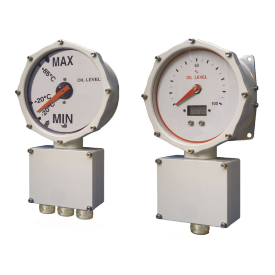
Page 3: Drawings
TRANSFORMER COMPONENTS — 2. Drawings Comem OLI Figure 1 Comem eOLI Figure 2... -
Page 4: Mounting Flange
L I Q U I D L E V E L I N D I C AT O R - INSTRUCTION MANUAL — 2. Drawings Mounting flange 2.3.1 Comem OLI/Comem eOLI (radial) Figure 3 2.3.2 Comem OLI/ Comem eOLI (axial) Figure 4... -
Page 5: Comem Oli22 / Eoli22 (Radial)
TRANSFORMER COMPONENTS — 2. Drawings 2.3.3 Comem OLI22 / Comem eOLI22 (radial) Figure 5 2.3.4 Comem OLI22 / Comem eOLI22 (axial) Figure 6 NOTE “4 HOLES” MOUNTING FLANGE MAY BE DESIGNED IN ACCORDANCE WITH CUSTOMER’S NEED: UPON REQUEST, SEVERAL HOLE PATTERNS ARE AVAILABLE. -
Page 6: Comem L140
L I Q U I D L E V E L I N D I C AT O R - INSTRUCTION MANUAL — 2. Drawings Comem L140 2.4.1 Radial Figure 7 2.4.2 Axial Figure 8... -
Page 7: Comem L220
TRANSFORMER COMPONENTS — 2. Drawings Comem L220 2.5.1 Radial Figure 9 2.5.1 Axial Figure 10... -
Page 8: Comem L340
L I Q U I D L E V E L I N D I C AT O R - INSTRUCTION MANUAL — 2. Drawings Comem L340 2.6.1 Radial Figure 11 2.6.1 Axial Figure 12... -
Page 9: Comem Eviewer
TRANSFORMER COMPONENTS Comem eViewer Figure 13... -
Page 10: Operating Principle
Degree of protection IP66 according to EN60529 (Comem L340 available only IP65) Standard cable gland 1 x M25x1.5 Comem OLI – Comem OLI22 – Comem L140 – Comem eViewer 3 x M25x1.5 Comem eOLI – Comem eOLI22 Wires Max 2.5mm –... -
Page 11: Tests
TRANSFORMER COMPONENTS O I L L E V E L I N D I C AT O R - INSTRUCTION MANUAL — 3. Operating principle Other values may be agreed between purchaser and supplier. The minimum contact life shall be 1.000 NOTE operations. -
Page 12: Installation
L I Q U I D L E V E L I N D I C AT O R - INSTRUCTION MANUAL — 4. Installation Float assembly 4.1.1 LA version (radial) Screw the arm (Fig 14/A) into the hole of the backside shaft and block it with the M4 nut (Fig.14/B). -
Page 13: Liquid Level Indicator: General Information
20 NM) ON THE NUTS FOLLOWING A CROSS SEQUENCE. NOTE FOR THE LB CONFIGURATION ABB ADVICE TO FIT IT IN THE CENTER OF THE CONSERVATOR (S=0 - “S”: parameter that indicates an offset from the vertical conservator axis [mm]. It is available for LA (radial) configuration. -
Page 14: Comem L140
L I Q U I D L E V E L I N D I C AT O R - INSTRUCTION MANUAL — 4. Installation Comem L140 Comem OLI / Comem eOLI Insert the arm with float through the machined hole Place the o-ring on the slot behind the gauge on the conservator. Place the o-ring on the slot (Fig.83/B) . -
Page 15: Comem Oli22 / Eoli22 (With Special Flange)
TRANSFORMER COMPONENTS — 4. Installation Comem OLI22 / Comem Comem L220 eOLI22 (with special flange) Insert the arm with float through the machined hole on the conservator. Place the o-ring on the slot Insert the arm with float through the machined hole behind the gauge. -
Page 16: Comem L340
L I Q U I D L E V E L I N D I C AT O R - INSTRUCTION MANUAL — 4. Installation Comem L340 Comem eViewer • Insert the arm with float through the machined Arrange the transformer with a dedicated place hole on the conservator. -
Page 17: Electrical Connection
TRANSFORMER COMPONENTS — 5. Electrical connection CAUTION WARNING PROVIDE TO THE EDEVICE A POWER SUPPLY QUALIFIED AND SKILLED PERSONNEL TRAINED DISCONNECTION THROUGH AN EXTERNAL IN THE APPLICABLE HEALTH AND SAFETY REGULATIONS OF THE RELEVANT COUNTRY SWITCH (IF THE DEVICE IS INSTALLED IN A SHOULD ONLY PERFORM ELECTRICAL FIXED POSITION). -
Page 18: Micro-Switches Wiring
L I Q U I D L E V E L I N D I C AT O R - INSTRUCTION MANUAL — 5. Electrical connection Micro-switches wiring Wire the electrical cables in accordance with the ordered model following the electrical scheme showed in the figure 22. - Page 19 TRANSFORMER COMPONENTS — 5. Electrical connection Figure 25...
-
Page 20: Operation And Maintanence
EOLI-22/VIEWER DURING THE ELECTRICAL • That there are no breakages TRANSFORMER ROUTINE TEST. If damages are found, please contact ABB and provide the information from the shipping list and Maintenance the serial number. During regular maintenance on the transformer, we... -
Page 21: Appendix A: Modbus Communication
TRANSFORMER COMPONENTS — Appendix A: MODBUS communication MODBUS register Register address Operation Notes Operation for monitoring 0x2000 Level value (0-100%) 0x2001 Minutes from the last powering 0x2002 Days from the last powering 0x2003 Max level value (%) in the current day 0x2004 Min level value (%) in the current day 0x2005... -
Page 22: Modbus Address
L I Q U I D L E V E L I N D I C AT O R - INSTRUCTION MANUAL — Appendix A: MODBUS communication A1.1 MODBUS address ADDRESS When are installed two or more units, it is necessary to differentiate the MODBUS address changing the dip-switches position. - Page 23 TRANSFORMER COMPONENTS...
- Page 24 The data and illustrations are not binding. We reserve the right to modify 36054 Montebello Vicentino (VI) - ITALY the contents of this document without prior notice following technical and product developments. www.abb.com/transformercomponents © Copyright 2020 ABB. All rights reserved.