
Related Manuals for TFC 099A

Summary of Contents for TFC 099A
- Page 1 Cat No. 099A Digital Programmable Thermostat Weekday/Weekend Setting User Maunal...
-
Page 2: Table Of Contents
TABLE OF CONTENT 1 INTRODUCTION……………………………………. 2 2 INSTALLATION…………………………………….…4 3 SETTING CLOCK …………………………………. 11 4 SETTING PROGRAM……………………………...12 5 SLEEP OPERATION MODE……………………… 15 6 MANUAL OVERRIDE …………………………...…15 7 HEATER OPERATION……………………………..17 8 LOW BATTERY OPERATION……………………. 18 9 SPECIFICATIONS…………………………………. 19... -
Page 3: Introduction
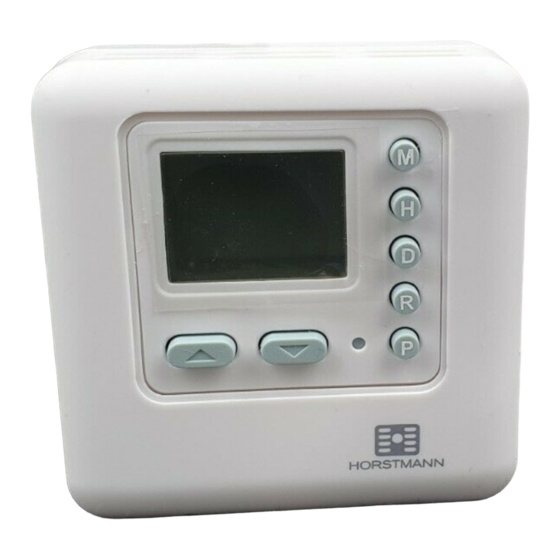
1 INTRODUCTION This thermostat can replace most common indoor resi- dential thermostat and is designed to be used with elec- tric, gas or oil heating system. 1.1 Outlook... - Page 4 1.2 LCD 1.3 Features Several useful functions and operating modes have been incorporated to adapt a variety of customer needs. • LCD shows the “NEED TO KNOW” Information only, which is more easy to understand • 8 Changeable Programs (4 programs for weekday; 2 programs each for Saturday and Sunday) •...
-
Page 5: Installation
• Simplified Temperature Adjustment • Simplified Programming Procedure • Manual Set-Temperature Override • 2 x AAA Size Alkaline Batteries Operation (Not Included) • Low Battery Indication • Heater Operation Mode • Sleep Operation Mode • Slim Housing Design 2 INSTALLATION This thermostat has been designed for simple and quick installation requiring only a few tools. - Page 6 2.1 Required Material Hammer Masking tape Drill and 3/16” drill bit Screwdriver 2.2 Removing your old thermostat CAUTION: To avoid electric shock, turn off the power of the heating system at the main power box in your home. Read the following instructions carefully before discon- necting the wires.
- Page 7 Warning: After removing the wall plate, if you find that it is mounted on a junction box (e.g. a box similar to one behind a light switch or electric outlet), high voltage cir- cuit may be present and there is a danger of electric shock.
- Page 8 2. Away from: i. Drafts of dead air sports ii. Air ducts iii.Radiant heat from the sun or appliances iv.Concealed pipes and chimneys 3. The best viewing angle is 12 o’clock direction as shown in figure. 2.5 Mounting 1. Mounting the thermostat onto the wall. 2.
- Page 9 2.6 Connecting the Wires 1. Connect the system wires to the terminals according to the wiring diagram shown in the section 2.7 “WIRING DIAGRAM”. 2.7 Wiring Diagram The DRT2 thermostat can be used with single stage heating system. Inside the thermostat, three terminals which label COM, NC and NO would be found.
- Page 10 pends on the type of heater), In most case, COM and NO are used. 2.8 Battery Installation Alkaline The DRT2 is operated by two AAA 1.5V batter- ies. Please follow the installation instruction: 1. Find out the battery door at the side of the case. 2.
- Page 11 If first use, skips the instruction (3) and (4). 2.9 Temperature Span Span is the temperature difference between the turn ON and OFF temperature. The factory pre-set span is 2˚C. For example, control temperature setting is 20.0˚C. The heater will be operated when the room temperature drops to 19.5˚C and will be turned off when the temperature rises to 21˚C.
-
Page 12: Setting Clock
To power-up the unit, installs battery as shown in above section “Battery Installation”. When power is applied for the first time or reset button is pressed, the display will show as follows: TIME 0:00 MONDAY TEMPERATURE 22˚C OUTPUT If the display is different as shown, use a fine probe such as straightened paper clip to gently push the reset button. -
Page 13: Setting Program
3. Press H button to adjust the hour digits. 4. Press M button to adjust the minute digits. 5. Hold D, H or M button about 3 seconds to fast advance the day, hour or minute adjustment rate respectively. 6. Press R button to return to normal operation mode. 7. - Page 14 1. After power up or reset, press P button to view the prerecorded programs. All the programs are factory preset at the above values. 2. Press P button again will scroll weekday (P1 - 4), Saturday (P5 - 6) and Sunday (P7 - 8) programs. 3.
- Page 15 temperature. Temperature will be increased or decreased by 0.5˚C for each press. 5. Program temperature can only be set in the control temperature range from 5˚C to 35˚C, not wrap around at two ends. 6. Press D button will turn on or off the program.
-
Page 16: Sleep Operation Mode
5 SLEEP OPERATION MODE Sleep operation is used to save power when not use. Pressing the L and M simultaneously about 5 seconds will activate the sleep operation mode. When enter the sleep operation mode, all function will be paused, the LCD will be blank and the relay will turn off. Pressing any key to call the unit wake up. - Page 17 3. Press L or M button to decrease or increase the temperature setting. 4. Hold L or M button to fast advances the adjustment rate. 5. Press R button to terminate the setting procedure and back to normal mode with the new temperature setting.
-
Page 18: Heater Operation
Likewise, when pressing M button to decrease the temperature to 5˚C, the “down arrow” of the Manual Override Icon will be turned off as shown. 7 HEATER OPERATION 7.1 Heater On Operation The heater will be turned on by setting programs or manual override. -
Page 19: Low Battery Operation
7.2 Output-On Delay For safety purposes, the thermostat has an auto 20 seconds’ delay for heater to restart. 8 LOW BATTERY OPERATION When the voltage of the battery decrease to certain level, the low battery indicator will be turned on and the thermostat cannot detect the temperature anymore. -
Page 20: Specifications
9 SPECIFICATIONS 9.1 Physical Characteristics Size: 73.5 (W) X 28.0 (L) X 73.5 (H) mm Material: Polycarbonate (PC) Weight: 94g (battery not included) 9.2 Electrical Characteristics Alkaline Power Source: AAA 1.5V battery x 2 (not included) Switching Relay: Resistive load: 5A at 250VAC Inductive load: 3.5A at 250VAC... - Page 21 Output On Delay: 20 seconds Operating Temperature: -10˚C to 50˚C (non-condensing) Storage Temperature: -30˚C to 60˚C...