Table of Contents
Advertisement
This equipment has been tested and found to comply with the limits of a Class B digital device,
pursuant to Part 15 of the FCC Rules. These limits are designed to provide reasonable protection
against harmful interference in a residential installation. This equipment generates, uses, and can
radiate radio frequency energy and, if not installed and used in accordance with the instructions,
may cause harmful interference to radio communications. There is no guarantee that interference
will not occur in a particular installation.
The vendor makes no representations or warranties with respect to the contents here and
specially disclaims any implied warranties of merchantability or fitness for any purpose. Further
the vendor reserves the right to revise this publication and to make changes to the contents here
without obligation to notify any party beforehand.
Duplication of this publication, in part or in whole, is not allowed without first obtaining the
vendor's approval in writing.
The content of this user's manual is subject to be changed without notice and we will not be
responsible for any mistakes found in this user's manual. All the brand and product names are
trademarks of their respective companies.
FCC Information and Copyright
Dichiarazione di conformità sintetica
Ai sensi dell'art. 2 comma 3 del D.M. 275 del
30/10/2002
Si dichiara che questo prodotto è conforme
alle normative vigenti e soddisfa i requisiti
essenziali richiesti dalle direttive
2004/108/CE, 2006/95/CE e 1999/05/CE
quando ad esso applicabili
Short Declaration of conformity
We declare this product is complying with the
laws in force and meeting all the essential
requirements as specified by the directives
2004/108/CE, 2006/95/CE and 1999/05/CE
whenever these laws may be applied
Advertisement
Table of Contents

Related Manuals for Biostar A70MD PRO


Summary of Contents for Biostar A70MD PRO
-
Page 1: Fcc Information And Copyright
FCC Information and Copyright This equipment has been tested and found to comply with the limits of a Class B digital device, pursuant to Part 15 of the FCC Rules. These limits are designed to provide reasonable protection against harmful interference in a residential installation. This equipment generates, uses, and can radiate radio frequency energy and, if not installed and used in accordance with the instructions, may cause harmful interference to radio communications. -
Page 2: Table Of Contents
Table Of Contents FCC Information and Copyright ������������������������������������������������������������������������������� 1 Chapter 1: Introduction ������������������������������������������������������������������������������������������� 3 1.1 Before You Start ........................3 1.2 Package Checklist ........................ 3 1.3 Specifications ........................4 1.4 Rear Panel Connectors ......................5 1.5 Motherboard Layout ......................6 Chapter 2: Hardware installation �����������������������������������������������������������������������������... -
Page 3: Chapter 1: Introduction
A70MD PRO / A68MD PRO / A70MG PRO Chapter 1: Introduction 1�1 Before You Start Thank you for choosing our product. Before you start installing the motherboard, please make sure you follow the instructions below: • Prepare a dry and stable working environment with sufficient lighting. -
Page 4: Specifications
Form Factor, 226 mm x 174 mm Windows XP/ 7/ 8/ 8.1/10 (*Some CPUs may not support Windows XP.) OS Support Biostar reserves the right to add or remove support for any OS with or without notice. 4 | Chapter 1: Introduction... -
Page 5: Rear Panel Connectors
A70MD PRO / A68MD PRO / A70MG PRO 1.4 Rear Panel Connectors A70MD PRO/A68MD PRO A70MG PRO Note » DVI-D / VGA output require an AMD family processor with intedrated graphics. » Since the audio chip supports High Definition Audio Specification, the function of each audio jack can be defined by software. The input / output function of each audio jack listed above represents the default setting. However, when connecting external microphone to the audio port, please use the Line In (Blue) and Mic In (Pink) audio jack. » Maximum resolution VGA: 1920 x 1600 @60Hz DVI-D: 1920 x 1200 @60Hz / 2560 x 1600 @60Hz Chapter 1: Introduction | 5... -
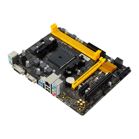
Page 6: Motherboard Layout
1.5 Motherboard Layout Note » represents the 1st pin. 6 | Chapter 1: Introduction... -
Page 7: Chapter 2: Hardware Installation
A70MD PRO / A68MD PRO / A70MG PRO Chapter 2: Hardware installation 2.1 Install Central Processing Unit (CPU) Step 1: Locate the CPU socket on the motherboard Step 2: Pull the socket locking out from the socket and then raise the lever up to a 90-degree angel. -
Page 8: Install A Heatsink
Step 4: Hold the CPU down firmly, and then close the lever to locked the position 2.2 Install a Heatsink Step 1: Place the heatsink and fan assembly onto the retention frame. Match the heatsink clip with the socket mounting-lug. Hook the spring clip to the mounting-lug. Step 2: On the other side, push the retention clip straight down to lock into the plastic lug on the retention frame, and then press down the locker until it stops. -
Page 9: Connect Cooling Fans
A70MD PRO / A68MD PRO / A70MG PRO 2.3 Connect Cooling Fans These fan headers support cooling-fans built in the computer. The fan cable and connector may be different according to the fan manufacturer. CPU_FAN1: CPU Fan Header Pin Assignment... - Page 10 Step 1: Unlock a DIMM slot by pressing the retaining clips outward. Align a DIMM on the slot such that the notch on the DIMM matches the break on the slot. Step 2: Insert the DIMM vertically and firmly into the slot until the retaining clips snap back in place and the DIMM is properly seated.
-
Page 11: Expansion Slots
A70MD PRO / A68MD PRO / A70MG PRO 2.5 Expansion Slots PEX16_1: PCI-Express Gen3 x16 Slot • PCI-Express 3.0 compliant. • Maximum theoretical realized bandwidth of 16GB/s simultaneously per direction, for an aggregate of 32GB/s totally. PEX1_1: PCI-Express Gen3 x1 Slot • ... -
Page 12: Jumper & Switch Setting
2.6 Jumper & Switch Setting The illustration shows how to set up jumpers. When the jumper cap is placed on pins, the jumper is “close”, if not, that means the jumper is “open”. Pin opened Pin closed Pin 1-2 closed JCMOS1: Clear CMOS Jumper The jumper allows users to restore the BIOS safe setting and the CMOS data. -
Page 13: Headers & Connectors
A70MD PRO / A68MD PRO / A70MG PRO 2.7 Headers & Connectors ATXPWR1: ATX Power Source Connector For better compatibility, we recommend to use a standard ATX 24-pin power supply for this connector. Make sure to find the correct orientation before plugging the connector. - Page 14 PANEL1: Front Panel Header This 16-pin header includes Power-on, Reset, HDD LED, Power LED, and speaker connection. Pin Assignment Function Pin Assignment Function 10 N/A Speaker Connector 11 N/A Speaker 12 Power LED (+) Power HDD LED (+) Hard drive 13 Power LED (+) HDD LED (-) 14 Power LED (-)
- Page 15 A70MD PRO / A68MD PRO / A70MG PRO F_USB1/2: Header for USB 2.0 Ports at Front Panel This header allows user to add additional USB ports on the PC front panel, and also can be connected with a wide range of external peripherals.
-
Page 16: Chapter 3: Uefi Bios & Software
The BIOS can be updated using either of the following utilities: • BIOSTAR BIOS Flasher: Using this utility, the BIOS can be updated from a file on a hard disk, a USB drive (a flash drive or a USB hard drive), or a CD-ROM. - Page 17 A70MD PRO / A68MD PRO / A70MG PRO 6. Select the proper BIOS file, and a message asking if you are sure to flash the BIOS file. Click “Yes” to start updating BIOS. 7. A dialog pops out after BIOS flash is completed, asking you to restart the system.
- Page 18 Then, the BIOS Update is completed. BIOS Update Utility (through a BIOS file) 1. Installing BIOS Update Utility from the DVD Driver. 2. Download the proper BIOS from http://www.biostar.com.tw/ 3. Launch BIOS Update Utility and click the “Update BIOS” button on the main screen.
- Page 19 A70MD PRO / A68MD PRO / A70MG PRO 5. Choose the location for your BIOS file in the system. Please select the proper BIOS file, and then click on “Open”. It will take several minutes, please be patient. 6. After the BIOS Update process is finished, click on “OK”...
-
Page 20: Software
3.3 Software Installing Software Insert the Setup DVD to the optical drive. The driver installation program would appear if the Auto-run function has been enabled. Select Software Installation, and then click on the respective software title. Follow the on-screen instructions to complete the installation. Launching Software After the installation process is completed, you will see the software icon showing on the desktop. - Page 21 A70MD PRO / A68MD PRO / A70MG PRO eHot-Line eHot-Line is a convenient utility that helps you to contact with our Tech-Support system. This utility will collect the system information which is useful for analyzing the problem you may have encountered, and then send these information to our tech-support department to help you fix the problem.
- Page 22 Open the saved .txt file, you will see your system information including motherboard/BIOS/CPU/ video/device/OS information. This information is also concluded in the sent mail. Note » Before you use this utility, please set Outlook Express as your default e-mail client application program. » We will not share customer’s data with any other third parties, so please feel free to provide your system information while using eHot-Line service. » If you are not using Outlook Express as your default e-mail client application, you may need to save the system information to a .txt file and send the file to our tech support with other e-mail application. Go to the following website http://www.biostar.com.tw/app/en/about/contact.php for getting our contact information. 22 | Chapter 3: UEFI BIOS & Software...
-
Page 23: Chapter 4: Useful Help
A70MD PRO / A68MD PRO / A70MG PRO Chapter 4: Useful help 4.1 Driver Installation After you installed your operating system, please insert the Fully Setup Driver DVD into your optical drive and install the driver for better system performance. -
Page 24: Ami Bios Beep Code
4.2 AMI BIOS Beep Code Boot Block Beep Codes Number of Beeps Description Continuing Memory sizing error or Memory module not found POST BIOS Beep Codes Number of Beeps Description Success booting. Display memory error (system video adapter) 4.3 Troubleshooting Probable Solution 1. -
Page 25: Raid Functions
A70MD PRO / A68MD PRO / A70MG PRO CPU Overheated If the system shutdown automatically after power on system for seconds, that means the CPU protection function has been activated. When the CPU is over heated, the motherboard will shutdown automatically to avoid a damage of the CPU, and the system may not power on again. - Page 26 Data are stored twice by writing them to both the data disk (or set of data disks) and a mirror disk (or set of disks) . If a disk fails, the controller uses either the data drive or the mirror drive for data recovery and continues operation. You need at least 2 disks for a RAID 1 array.
-
Page 27: Amd Dual Graphics Technology
A70MD PRO / A68MD PRO / A70MG PRO 4.5 AMD DUAL Graphics Technology AMD Dual Graphics Technology Introduction When user adds a PCIE display adapter, it can be integrated with IGD to show better performance. To make the two video devices work simultaneously and normally, please refer to the following setting. -
Page 28: Appendix I: Specifications In Other Languages
DIMM www.biostar.com.tw A70M SATA AHCI / 10 RAID RTL 8111G, REALTEK 1000 ALC662 AMD A70M PCIe x1 16 x3.0 PCIe PS/2 PS/2 (A70MD PRO/A68MD PRO) DVI x SATA microATX windows xp BIOSTAR 28 | APPENDIX I: Specifications in Other Languages... -
Page 29: German
1x Serieller Port-Header Formfaktor microATX Formfaktor, 226 mm x 174 mm Windows XP/ 7/ 8/ 8.1/10 OS-Unterstützung Biostar reserves the right to add or remove support for any OS with or without notice APPENDIX I: Specifications in Other Languages | 29... -
Page 30: Russian
1 контакт последовательного порта Конструктив Форм-фактор microATX, 226 мм x 174 мм Windows XP/ 7/ 8/ 8.1/10 Поддержка ОС Biostar оставляет за собой право добавлять или удалять поддержку любой ОС, с уведомлением или без. 30 | APPENDIX I: Specifications in Other Languages... -
Page 31: Spanish
Factor de Forma microATX, 226 mm x 174 mm Windows XP/ 7/ 8/ 8.1/10 Soporte OS Biostar reserva su derecho de añadir o retirar el soporte para cada OS con o sin notificación. APPENDIX I: Specifications in Other Languages | 31... -
Page 32: Thai
สนั บ สนุ น OS Biostar ขอสงวนสิ ท ธิ ์ ใ นการเพิ ่ ม หรื อ ถอดการสนั บ สนุ น สำหรั บ ระบบปฏิ บ ั ต ิ ก าร OS ต่ า งๆ โดยไม่ ต ้ อ งแจ้ ง ให้ ท ราบล่ ว งหน้ า...