Samsung LNT3253H Service Manual
Chassis gbp32mus & gbp40mus
Hide thumbs
Also See for LNT3253H:
- Owner's instructions manual (191 pages) ,
- Owner's instructions manual (189 pages) ,
- Owner's instructions manual (191 pages)
Table of Contents
Advertisement
SERVICE
LCD TV
LCD-TV
Chassis
GBP32MUS
GBP40MUS
Model
LNT3253H
LNT4053H
Manual
Fashion Feature
- Digital-TV, RF, 3-HDMI, 2-Component,
2-A/V, 2-S-Video, USB2.0(WISELINK), D-SUB
- Brightness : 500cd/
- Contrast Ratio : 7000:1
- Response time : 8ms
- Dynamic contrast
- PIP( in HDMI1.2.3, Component1.2, PC Mode
and Sub picture is available only in TV
anolog mode.)
Advertisement
Table of Contents

Related Manuals for Samsung LNT3253H


Summary of Contents for Samsung LNT3253H
- Page 1 LCD-TV Chassis GBP32MUS GBP40MUS Model LNT3253H LNT4053H SERVICE Manual LCD TV Fashion Feature - Digital-TV, RF, 3-HDMI, 2-Component, 2-A/V, 2-S-Video, USB2.0(WISELINK), D-SUB - Brightness : 500cd/ - Contrast Ratio : 7000:1 - Response time : 8ms - Dynamic contrast - PIP( in HDMI1.2.3, Component1.2, PC Mode and Sub picture is available only in TV anolog mode.)
- Page 2 Copyright Trademarks Samsung is the registered trademark of Samsung ©2007 by Samsung Electronics Co., Ltd. Electronics Co., Ltd. All rights reserved. LNT3253H/LNT4053H and MacMaster Cable Adapter This manual may not, in whole or in part, be copied, are trademarks of Samsung Electronics Co., Ltd.
-
Page 3: Table Of Contents
… ………………………………………………………………………………………………………………………………4-1 Exploded View and Parts List … … ……………………………………………………………………………………………………………5-1 5-1 LNT3253H Exploded View ……………………………………………………………………………………………………………… 5-1 5-2 LNT3253H Parts list ……………………………………………………………………………………………………………………… 5-2 5-3 LNT4053H Exploded View ……………………………………………………………………………………………………………… 5-3 5-4 LNT4053H Parts list ……………………………………………………………………………………………………………………… 5-4 Electrical Parts List … … …………………………………………………………………………………………………………………………6-1 6-1 LNT3253H Parts List ……………………………………………………………………………………………………………………... - Page 4 Contents Schematic Diagrams … … …………………………………………………………………………………………………………………………9-1 0 Operating Instructions and Installation … … …………………………………………………………………………………………………10-1 10-1 Front …………………………………………………………………………………………………………………………………… 10-1 10-2 Connection Panel ……………………………………………………………………………………………………………………… 10-2 10-3 Remote Control ………………………………………………………………………………………………………………………… 10-4 1 Disassembly and Reassembly … … ……………………………………………………………………………………………………………11-1 11-1 Disassembly …………………………………………………………………………………………………………………………… 11-1 11-2 Reassembly …………………………………………………………………………………………………………………………… 11-6 2 Schematic Diagram …...
- Page 5 Samsung Electronics Co.,Ltd. - This Service Manual is a property of Samsung 416, Maetan-3Dong, Yeongtong-Gu, Suwon City, Electronics Co., Ltd. Gyeonggi-Do, Korea, 443-742 Any unauthorized use of Manual can be Printed in Korea punished under applicable International and/or P/N : BN82-00185A-00 domestic law.
-
Page 6: Precautions
1 Precautions 1 Precautions Follow these safety, servicing and ESD precautions to prevent damage and to protect against potential hazards such as electrical shock. 1-1 Safety Precautions 1-1-1 Warnings For continued safety, do not attempt to modify the circuit board. Disconnect the AC power and DC power jack before servicing. -
Page 7: Servicing Precautions
1 Precautions 1-2 Servicing Precautions WARNING: An electrolytic capacitor installed with the wrong polarity might explode. Caution: Before servicing units covered by this service manual, read and follow the Safety Precautions section of this manual. Note: If unforeseen circumstances create conflict between the following servicing precautions and any of the safety precautions, always follow the safety precautions. -
Page 8: Installation Precautions
1 Precautions 1-4 Installation Precautions 1. For safety reasons, more than two people are 7. When installing the product, leave enough space required for carrying the product. (10cm) between the product and the wall for ventilation purposes. 2. Keep the power cord away from any heat emitting A rise in temperature within the product may cause fire. - Page 9 1 Precautions Memo...
-
Page 10: Product Specifications
2 Product Specifications 2 Product Specifications 2-1 Features - Digital-TV, RF, 3-HDMI, 2-Component, 2-A/V, 2-S-Video, USB2.0(WISELINK), D-SUB - Brightness : 500cd/㎥ - Contrast Ratio : 7000 : 1 - Response time : 8ms - Dynamic contrast - PIP( in HDMI1.2.3, Component1.2, PC Mode and Sub picture is available only in TV anolog mode.) -
Page 11: Specifications
2 Product Specifications 2-2 Specifications 2-2-1 LNT3253H Specifications Item Description TFT-LCD panel, RGB vertical stripe, SPVA mode, normaly black, 32-Inch viewable, LCD Panel 0.51075 (H) x 0.1705 (W) x 3 mm pixel pitch Horizontal : 30 kHz ~ 61 kHz (Automatic) / Vertical : 60 Hz ~ 75 Hz (Automatic) - Page 12 2 Product Specifications 2-2-2 LNT4053H Specifications Item Description TFT-LCD panel, RGB vertical stripe, SPVA mode, normaly black, 40-Inch viewabe, LCD Panel 0.648(H) x 0.216(W) x 3 mm pixel pitch Horizontal : 30 kHz ~ 61 kHz (Automatic) / Vertical : 60 Hz ~ 75 Hz (Automatic) Scanning Frequency Display Colors 16.7 Million colors...
- Page 13 2 Product Specifications 2-2-3 Spec Comparison LN32R71BD, LN40R71BD LNT3253H, LNT4053H Model Design requency Horizontal 30 ~ 61 kHz 30 ~ 61 kHz Vertical 60 ~ 75 Hz 60 ~ 75 Hz Display Color 16,777,216 colors 16,777,216 colors C Resolution 1360 x 768 / 60 Hz...
-
Page 14: Option Specification
2 Product Specifications 2-3 Option Specification Item Item Name Code.No Remark Remote Control & BN59-00599A Batteries (AAA x 2) Power Cord 3903-000144 Cover-Bottom BN63-03103B 32" : BN96-04662A Stand 40" : BN96-04661A Stand Screw (4 ea) 6002-001294 Owner's Instructions BN68-01156B Cleaning Cloth BN63-01798A Warranty Card / Registration... - Page 15 2 Product Specifications Memo...
-
Page 16: Alignments And Adjustments
3 Alignments and Adjustments 3 Alignments and Adjustments 3-1 General Alignment Instuction 1. Usually, a color LCD-TV needs only slight touch-up adjustment upon installation. Check the basic characteristics such as height, horizontal and vertical sync. 2. Use the specified test equipment or its equivalent. 3. -
Page 17: Factory Mode Adjustments
3 Alignments and Adjustments 3-2 Factory Mode Adjustments 3-2-1 Entering Factory Mode To enter 'Service Mode' Press the remote -control keys in this sequence : - If you do not have Factory remote - control Power OFF MUTE Power On 3-2-2 How to Access Service Mode Using the Customer Remote 1.Turn the power off and set to stand-by mode... - Page 18 3 Alignments and Adjustments HDMI Polarity Panel Display Time 70Hr HDMI-DTV Watchdog Enable Mute Time[RF] Calibration Submicom Download Spread Spectrum >> CH Memory SAMEX Option Byte Checksum MODEL BordPlus shop mode White Balance KS1410 Panel Option 32AM Downloadable RRT W/B MOVIE Dynamic Contrast PWM Dimming PC Mode ident...
- Page 19 3 Alignments and Adjustments Sharpness >> LNA PLUS >> H2gain UV Dealy >> HDMI-DTV H4gain >> Calibration Submicom Download V2gain Calibration Target >> Option Byte Checksum V4gain CLK_A White Balance KS1410 Sr2gain CLK_B W/B MOVIE Dynamic Contrast Sr4gain Roffset SVP-PX EEPROM Access Count Sl2gain Goffset...
- Page 20 3 Alignments and Adjustments Sharpness >> LNA PLUS >> UV Dealy >> >> Calibration Target >> TCD3_Contrast CLK_A TCD3_Bright CLK_B TCD3_YC_Delay Roffset ANALOG_Y_Offset Goffset ANALOG_PB_Offset Boffset ANALOG_PR_Offset BGain ANALOG_Y_Gain GGain ANALOG_PB_Gain BGain ANALOG_PR_Gain Sharpness >> 1st_AV_LOW 0x10 2st_AV_High 0xEB LNA PLUS >>...
- Page 21 3 Alignments and Adjustments Patt-Sel Skin-Enable B-Slope Gain Skin-Tu B-Tilt Min Skin-Tv HDMI-DTV B-Tilt Max Sub Color Calibration Submicom Download Lfunc Basis M-Skin-Tu Option Byte Checksum Hfunc Basis M-Skin-Tv White Balance KS1410 Mean offset1 M-Au-Sub color W/B MOVIE Dynamic Contrast Mean offset2 MW_Skin Tu SVP-PX...
- Page 22 3 Alignments and Adjustments HDMI-DTV Calibration Submicom Download Option Byte Checksum White Balance KS1410 W/B MOVIE Dynamic Contrast SVP-PX EEPROM Access Count FBE2 RESET MSP44XX NTP3000 T-BRDPAUS0_0024 Jan 22 2007 Submicom Download T-BRDPAUS5_C008 [Sec : 08] HDMI-DTV Calibration Submicom Download Option Byte Checksum White Balance...
- Page 23 3 Alignments and Adjustments HDMI-DTV Calibration Submicom Download Option Byte Checksum White Balance KS1410 W/B MOVIE Dynamic Contrast SVP-PX EEPROM Access Count FBE2 RESET MSP44XX Dynamic CE NTP3000 Dynamic Dimming T-BRDPAUS0_0024 Jan 22 2007 FBE2 Y_MEAN READ T-BRDPAUS5_C008 [Sec : 08] Addr:2906, Cnt: Addr:2907, Cnt: Addr:2905, Cnt:...
-
Page 24: White Balance - Calibration
3 Alignments and Adjustments 3-3 White Balance - Calibration 3-3-1 White Balance -Calibration 1. Calibration DTV Calibration PC Calibration (Calibration Condition refer to next page) 3-3-2 White Balance - Adjustment (low light) (hight light) 3. W/B Sub Bright Sub Contrast R offset R gain G offset... -
Page 25: White Ratio (Balance) Adjustment
3 Alignments and Adjustments 3-4 White Ratio (Balance) Adjustment 1. You can adjust the white ratio in factory mode (1:Calibration, 3:White-Balance). 2. Since the adjustment value and the data value vary depending on the input source, you have to adjust these in CVBS, Component 1 and HDMI 1 modes. 3. -
Page 26: Servicing Information
3 Alignments and Adjustments 3-5 Servicing Information 3-5-1 USB Download Method 1. Downloading boot code (1) Change the the boot code's file name into "boot.bin" and application code's into "appl.rom" (2) Copy the Upgrade Files into the path "\bordplus\us" in USB flash driver. (3) Turn off LCD TV. - Page 27 3 Alignments and Adjustments Memo 3-12...
-
Page 28: Troubleshooting
4 Troubleshooting 4 Troubleshooting 4-1 No Power Panel Lamp Off, power indicator Check power cable connection LED red color? P/N : BN39-00802A Does proper Stand-By DC A5V Change the Main Power Ass'y appear at C103L? 32" : BN44-00155A 40: : BN44-00165A Does proper Main DC B18VS, B5V, B13V appear at C118,C133,C135? - Page 29 Does the digital data appear at Check IC1101 output of R915~R920? Change the main PCB ass'y Does the digital data Check IC901 appear at output of Change the main PCB ass'y R1136~R1146? Check the LVDS cable? Please call 1 800 Samsung Replace the LCD panel?
- Page 30 4 Troubleshooting WAVEFORMS PC Input (V-Sync, H-Sync) LVDS Out (CLK + / -)
- Page 31 Check IC1101 at output of R1136~R1146? Change the main PCB ass'y Does the digital data appear Check IC901 at output of R1136~R1146? Change the main PCB ass'y Check the LVDS cable? Please call 1 800 Samsung Replace the LCD panel?
- Page 32 4 Troubleshooting WAVEFORMS HDMI Input (CLK + / -)
- Page 33 Check IC1101 appear at output of Change the main PCB ass'y R1136~R1146? Does the digital data Check IC901 appear at output of Change the main PCB ass'y R1136~R1146? Check the LVDS cable? Please call 1 800 Samsung Replace the LCD panel?
- Page 34 4 Troubleshooting WAVEFORMS Tuner CVBS Out (Pattern: Grey Bar)
- Page 35 Does the digital data appear at output of R1136~R1146? Change the main PCB ass'y Check IC901 Does the digital data appear Change the main PCB ass'y at output of R1136~R1146? Check the LVDS cable? Please call 1 800 Samsung Replace the LCD panel?
- Page 36 4 Troubleshooting WAVEFORMS TS DATA Out (Clk, Data [0]) Eagle+ Out (Clk, H-Sync)
- Page 37 Check IC1101 at output of R1136~R1146? Change the main PCB ass'y Does the digital data appear Check IC901 at output of R1136~R1146? Change the main PCB ass'y Check the LVDS cable? Please call 1 800 Samsung Replace the LCD panel? 4-10...
- Page 38 Change the main PCB ass'y R1136~R1146? Does the digital data Check IC901 appear at output of Change the main PCB ass'y R1136~R1146? Check the LVDS cable? Please call 1 800 Samsung Replace the LCD panel? 4-11...
- Page 39 4 Troubleshooting WAVEFORMS S-VIDEO Input (Y/C) 4-12...
- Page 40 Change the main PCB ass'y R1136~R1146? Does the digital data Check IC901 appear at output of Change the main PCB ass'y R1136~R1146? Check a LVDS cable? Please call 1 800 Samsung Replace a LCD panel? 4-13...
- Page 41 4 Troubleshooting WAVEFORMS Component Input (Y/Pb) 4-14...
- Page 42 Does the digital data appear Check IC302 at #4~#6,#69(Mclk, Sclk, Change the main PCB ass'y LRclk, data) of IC302? Check IC401 Does the signal appear at Change the main PCB ass'y L401,L402 (L/R output)? Replace the speaker ass'y? Please call 1 800 Samsung 4-15...
- Page 43 4 Troubleshooting WAVEFORMS Audio Input (Sign Wave) 12S Input (Clk, Data) Audio Amp Out (Sign Wave) 4-16...
-
Page 44: Lnt3253H Exploded View
5 Exploded View & Parts List 5 Exploded View and Parts List - You can search for updated part codes through ITSELF web site. URL : http://itself.sec.samsung.co.kr/ 5-1 LNT3253H Exploded View M0013 M0146 M0115 T0447 M0215 T0003 M0013... -
Page 45: Lnt3253H Parts List
5 Exploded View & Parts List 5-2 LNT3253H Parts list Location Code.No Item & Specification Q'ty SA/SNA Remark T0003 BN96-04658A ASSY COVER P-FRONT;32R81,UO,-,PC,V0,BK27 M0215 BN07-00385A LCD-PANEL;LTA320WT-L07,8bit,32inch,16.7M T0447 BN96-04681E ASSY BRACKET P-PANEL;32R81,AM,CMO,SMPS,G S.N.A M0115 BN61-02965A BRACKET-STAND LINK;32 BORDEAUX PLUS,SECC S.N.A M0146 BN61-02419A BRACKET-PANEL SIDE;SONOMA 32,SECC,T1.2,A... -
Page 46: Lnt4053H Exploded View
5 Exploded View & Parts List 5-3 LNT4053H Exploded View M0014 M0146 M0013 M0146 M0115 T0447 M0215 T0003 M0013... -
Page 47: Lnt4053H Parts List
5 Exploded View & Parts List 5-4 LNT4053H Parts list Location Code.No Item & Specification Q'ty SA/SNA Remark T0003 BN96-04656A ASSY COVER P-FRONT;40R81,UO,-,PC,V0,BK27 M0215 BN07-00387A LCD-PANEL; LTA400WT-L06,8bit,40inch,16.7 T0447 BN96-04679A ASSY BRACKET P-PANEL;BORDEAUX PLUS40 S.N.A M0115 BN61-02882A BRACKET-STAND LINK;TULIP,40,SECC,T1.6,-, S.N.A M0146 BN61-02256B BRACKET-PANEL SIDE;Bordeaux 40,SECC,T1.2 S.N.A... -
Page 48: Electrical Parts List
6 Electrical Parts List 6 Electrical Parts List -You can search for updated part codes through ITSELF web site. URL : http://itself.sec.samsung.co.kr/ 6-1 LNT3253HX Parts List Level Loc. No. Code No. Description & Specification Q'ty SA/SNA LNT3253HX/XAC LN-T3253H,N34A/32R80-GBP,32,LCD-TV,CANAD M0001 BN90-01145A ASSY COVER FRONT;32R81,UO,-,PC,V0,BK27,S... - Page 49 6 Electrical Parts List Level Loc. No. Code No. Description & Specification Q'ty SA/SNA ...3 JA333 3722-002360 JACK-PIN;3P,AU,GRN/BLU/RED,STRAIGHT ...3 JA333 3722-002362 JACK-PIN;2P,Sn,WHT/RED,STRAIGHT ...3 JA333 3722-002362 JACK-PIN;2P,Sn,WHT/RED,STRAIGHT ...3 JA333 3722-002362 JACK-PIN;2P,Sn,WHT/RED,STRAIGHT ...3 JA333 3722-002362 JACK-PIN;2P,Sn,WHT/RED,STRAIGHT ...3 JA333 3722-002363 JACK-PIN;3P,Sn,YEL/WHT/RED,STRAIGHT ...3 JA333 3722-002543 JACK-PIN;3P,Sn,RED/WHT/YEL,ANGLE ...3...
- Page 50 6 Electrical Parts List Level Loc. No. Code No. Description & Specification Q'ty SA/SNA ..4 D0254 0402-000553 DIODE-SCHOTTKY;SS24/B240,40V,2000mA,DO-2 ..4 D0254 0402-000553 DIODE-SCHOTTKY;SS24/B240,40V,2000mA,DO-2 ..4 D1101 0403-000620 DIODE-ZENER;RLZ5.6B,5.45-5.73V,500mW,LL- ..4 D1102 0403-000620 DIODE-ZENER;RLZ5.6B,5.45-5.73V,500mW,LL- ..4 D1103 0403-000620 DIODE-ZENER;RLZ5.6B,5.45-5.73V,500mW,LL- ..4 D1104 0403-000620 DIODE-ZENER;RLZ5.6B,5.45-5.73V,500mW,LL- ..4 D1105 0403-000620 DIODE-ZENER;RLZ5.6B,5.45-5.73V,500mW,LL- ..4...
- Page 51 6 Electrical Parts List Level Loc. No. Code No. Description & Specification Q'ty SA/SNA ..4 D646 0406-001172 DIODE-TVS;CDS3C30GTH,48V,SMD ..4 D702B 0406-001172 DIODE-TVS;CDS3C30GTH,48V,SMD ..4 D703B 0406-001172 DIODE-TVS;CDS3C30GTH,48V,SMD ..4 D704B 0406-001172 DIODE-TVS;CDS3C30GTH,48V,SMD ..4 D711B 0406-001172 DIODE-TVS;CDS3C30GTH,48V,SMD ..4 D712B 0406-001172 DIODE-TVS;CDS3C30GTH,48V,SMD ..4 D740B 0406-001172 DIODE-TVS;CDS3C30GTH,48V,SMD ..4...
- Page 52 6 Electrical Parts List Level Loc. No. Code No. Description & Specification Q'ty SA/SNA ..4 IC012 1203-002995 IC-POSI.ADJUST REG.;AP1117D-A,TO-252,3P, ..4 T0170 1203-003059 IC-SWITCH VOL. REG.;MP1583,SOIC,8P,4.9x3 ..4 T0170 1203-003059 IC-SWITCH VOL. REG.;MP1583,SOIC,8P,4.9x3 ..4 IC701 1203-003394 IC-POWER SUPERVISOR;MIC2544-1YM,SOP,8P,4 ..4 T0087 1203-003696 IC-POSI.FIXED REG.;NCP1117DT18T5G,DPAK,3 ..4 T0087 1203-003696...
- Page 53 6 Electrical Parts List Level Loc. No. Code No. Description & Specification Q'ty SA/SNA ..4 R774 2007-000070 R-CHIP;0ohm,5%,1/10W,TP,1608 ..4 R814 2007-000070 R-CHIP;0ohm,5%,1/10W,TP,1608 ..4 R845 2007-000070 R-CHIP;0ohm,5%,1/10W,TP,1608 ..4 R880 2007-000070 R-CHIP;0ohm,5%,1/10W,TP,1608 ..4 R885 2007-000070 R-CHIP;0ohm,5%,1/10W,TP,1608 ..4 R887 2007-000070 R-CHIP;0ohm,5%,1/10W,TP,1608 ..4 R888 2007-000070 R-CHIP;0ohm,5%,1/10W,TP,1608 ..4...
- Page 54 6 Electrical Parts List Level Loc. No. Code No. Description & Specification Q'ty SA/SNA ..4 R1335 2007-000074 R-CHIP;100ohm,5%,1/10W,TP,1608 ..4 R1336 2007-000074 R-CHIP;100ohm,5%,1/10W,TP,1608 ..4 R1338 2007-000074 R-CHIP;100ohm,5%,1/10W,TP,1608 ..4 R1339 2007-000074 R-CHIP;100ohm,5%,1/10W,TP,1608 ..4 R1340 2007-000074 R-CHIP;100ohm,5%,1/10W,TP,1608 ..4 R1341 2007-000074 R-CHIP;100ohm,5%,1/10W,TP,1608 ..4 R1344 2007-000074 R-CHIP;100ohm,5%,1/10W,TP,1608 ..4...
- Page 55 6 Electrical Parts List Level Loc. No. Code No. Description & Specification Q'ty SA/SNA ..4 R336 2007-000074 R-CHIP;100ohm,5%,1/10W,TP,1608 ..4 R338 2007-000074 R-CHIP;100ohm,5%,1/10W,TP,1608 ..4 R341 2007-000074 R-CHIP;100ohm,5%,1/10W,TP,1608 ..4 R342 2007-000074 R-CHIP;100ohm,5%,1/10W,TP,1608 ..4 R4029 2007-000074 R-CHIP;100ohm,5%,1/10W,TP,1608 ..4 R601 2007-000074 R-CHIP;100ohm,5%,1/10W,TP,1608 ..4 R608 2007-000074 R-CHIP;100ohm,5%,1/10W,TP,1608 ..4...
- Page 56 6 Electrical Parts List Level Loc. No. Code No. Description & Specification Q'ty SA/SNA ..4 R1301 2007-000083 R-CHIP;3Kohm,5%,1/10W,TP,1608 ..4 R102L 2007-000084 R-CHIP;4.7Kohm,5%,1/10W,TP,1608 ..4 R1119 2007-000084 R-CHIP;4.7Kohm,5%,1/10W,TP,1608 ..4 R1122 2007-000084 R-CHIP;4.7Kohm,5%,1/10W,TP,1608 ..4 R1124 2007-000084 R-CHIP;4.7Kohm,5%,1/10W,TP,1608 ..4 R1128 2007-000084 R-CHIP;4.7Kohm,5%,1/10W,TP,1608 ..4 R1129 2007-000084 R-CHIP;4.7Kohm,5%,1/10W,TP,1608 ..4...
- Page 57 6 Electrical Parts List Level Loc. No. Code No. Description & Specification Q'ty SA/SNA ..4 R984 2007-000084 R-CHIP;4.7Kohm,5%,1/10W,TP,1608 ..4 R985 2007-000084 R-CHIP;4.7Kohm,5%,1/10W,TP,1608 ..4 R986 2007-000084 R-CHIP;4.7Kohm,5%,1/10W,TP,1608 ..4 R987 2007-000084 R-CHIP;4.7Kohm,5%,1/10W,TP,1608 ..4 R1004 2007-000090 R-CHIP;10Kohm,5%,1/10W,TP,1608 ..4 R104 2007-000090 R-CHIP;10Kohm,5%,1/10W,TP,1608 ..4 R1112 2007-000090 R-CHIP;10Kohm,5%,1/10W,TP,1608 ..4...
- Page 58 6 Electrical Parts List Level Loc. No. Code No. Description & Specification Q'ty SA/SNA ..4 R305 2007-000102 R-CHIP;100Kohm,5%,1/10W,TP,1608 ..4 R306 2007-000102 R-CHIP;100Kohm,5%,1/10W,TP,1608 ..4 R308 2007-000102 R-CHIP;100Kohm,5%,1/10W,TP,1608 ..4 R309 2007-000102 R-CHIP;100Kohm,5%,1/10W,TP,1608 ..4 R310 2007-000102 R-CHIP;100Kohm,5%,1/10W,TP,1608 ..4 R312 2007-000102 R-CHIP;100Kohm,5%,1/10W,TP,1608 ..4 R313 2007-000102 R-CHIP;100Kohm,5%,1/10W,TP,1608 ..4...
- Page 59 6 Electrical Parts List Level Loc. No. Code No. Description & Specification Q'ty SA/SNA ..4 R405 2007-000124 R-CHIP;2.2Kohm,5%,1/10W,TP,1608 ..4 R407 2007-000124 R-CHIP;2.2Kohm,5%,1/10W,TP,1608 ..4 R285 2007-000129 R-CHIP;27Kohm,5%,1/10W,TP,1608 ..4 R1101 2007-000309 R-CHIP;10ohm,5%,1/10W,TP,1608 ..4 R1102 2007-000309 R-CHIP;10ohm,5%,1/10W,TP,1608 ..4 R1103 2007-000309 R-CHIP;10ohm,5%,1/10W,TP,1608 ..4 R1104 2007-000309 R-CHIP;10ohm,5%,1/10W,TP,1608 ..4...
- Page 60 6 Electrical Parts List Level Loc. No. Code No. Description & Specification Q'ty SA/SNA ..4 R868 2007-000309 R-CHIP;10ohm,5%,1/10W,TP,1608 ..4 R869 2007-000309 R-CHIP;10ohm,5%,1/10W,TP,1608 ..4 R870 2007-000309 R-CHIP;10ohm,5%,1/10W,TP,1608 ..4 R871 2007-000309 R-CHIP;10ohm,5%,1/10W,TP,1608 ..4 R872 2007-000309 R-CHIP;10ohm,5%,1/10W,TP,1608 ..4 R873 2007-000309 R-CHIP;10ohm,5%,1/10W,TP,1608 ..4 R874 2007-000309 R-CHIP;10ohm,5%,1/10W,TP,1608 ..4...
- Page 61 6 Electrical Parts List Level Loc. No. Code No. Description & Specification Q'ty SA/SNA ..4 RA1606 2011-000881 R-NET;33ohm,5%,1/16W,L,CHIP,8P,TP,3.2x1..4 RA1607 2011-000881 R-NET;33ohm,5%,1/16W,L,CHIP,8P,TP,3.2x1..4 RA1608 2011-000881 R-NET;33ohm,5%,1/16W,L,CHIP,8P,TP,3.2x1..4 RA1609 2011-000881 R-NET;33ohm,5%,1/16W,L,CHIP,8P,TP,3.2x1..4 RA1610 2011-000881 R-NET;33ohm,5%,1/16W,L,CHIP,8P,TP,3.2x1..4 RA501 2011-000881 R-NET;33ohm,5%,1/16W,L,CHIP,8P,TP,3.2x1..4 RA502 2011-000881 R-NET;33ohm,5%,1/16W,L,CHIP,8P,TP,3.2x1.
- Page 62 6 Electrical Parts List Level Loc. No. Code No. Description & Specification Q'ty SA/SNA ..4 C1125 2203-000189 C-CER,CHIP;100nF,+80-20%,25V,Y5V,1608 ..4 C1126 2203-000189 C-CER,CHIP;100nF,+80-20%,25V,Y5V,1608 ..4 C1127 2203-000189 C-CER,CHIP;100nF,+80-20%,25V,Y5V,1608 ..4 C1128 2203-000189 C-CER,CHIP;100nF,+80-20%,25V,Y5V,1608 ..4 C1129 2203-000189 C-CER,CHIP;100nF,+80-20%,25V,Y5V,1608 ..4 C1130 2203-000189 C-CER,CHIP;100nF,+80-20%,25V,Y5V,1608 ..4 C1132 2203-000189 C-CER,CHIP;100nF,+80-20%,25V,Y5V,1608 ..4...
- Page 63 6 Electrical Parts List Level Loc. No. Code No. Description & Specification Q'ty SA/SNA ..4 C830 2203-000189 C-CER,CHIP;100nF,+80-20%,25V,Y5V,1608 ..4 C833 2203-000189 C-CER,CHIP;100nF,+80-20%,25V,Y5V,1608 ..4 C834 2203-000189 C-CER,CHIP;100nF,+80-20%,25V,Y5V,1608 ..4 C839 2203-000189 C-CER,CHIP;100nF,+80-20%,25V,Y5V,1608 ..4 C840 2203-000189 C-CER,CHIP;100nF,+80-20%,25V,Y5V,1608 ..4 C841 2203-000189 C-CER,CHIP;100nF,+80-20%,25V,Y5V,1608 ..4 C842 2203-000189 C-CER,CHIP;100nF,+80-20%,25V,Y5V,1608 ..4...
- Page 64 6 Electrical Parts List Level Loc. No. Code No. Description & Specification Q'ty SA/SNA ..4 C945 2203-000257 C-CER,CHIP;10nF,10%,50V,X7R,1608 ..4 C946 2203-000257 C-CER,CHIP;10nF,10%,50V,X7R,1608 ..4 C947 2203-000257 C-CER,CHIP;10nF,10%,50V,X7R,1608 ..4 C948 2203-000257 C-CER,CHIP;10nF,10%,50V,X7R,1608 ..4 C949 2203-000257 C-CER,CHIP;10nF,10%,50V,X7R,1608 ..4 C950 2203-000257 C-CER,CHIP;10nF,10%,50V,X7R,1608 ..4 C951 2203-000257 C-CER,CHIP;10nF,10%,50V,X7R,1608 ..4...
- Page 65 6 Electrical Parts List Level Loc. No. Code No. Description & Specification Q'ty SA/SNA ..4 C604 2203-000815 C-CER,CHIP;0.033nF,5%,50V,C0G,1608 ..4 C605 2203-000815 C-CER,CHIP;0.033nF,5%,50V,C0G,1608 ..4 C617 2203-000815 C-CER,CHIP;0.033nF,5%,50V,C0G,1608 ..4 C618 2203-000815 C-CER,CHIP;0.033nF,5%,50V,C0G,1608 ..4 C619 2203-000815 C-CER,CHIP;0.033nF,5%,50V,C0G,1608 ..4 C1310 2203-000838 C-CER,CHIP;0.39NF,5%,50V,C0G,TP,1608 ..4 C849 2203-000851 C-CER,CHIP;0.039nF,5%,50V,C0G,1608 ..4...
- Page 66 6 Electrical Parts List Level Loc. No. Code No. Description & Specification Q'ty SA/SNA ..4 C1733 2203-005005 C-CER,CHIP;100nF,10%,16V,X7R,1608 ..4 C1734 2203-005005 C-CER,CHIP;100nF,10%,16V,X7R,1608 ..4 C1735 2203-005005 C-CER,CHIP;100nF,10%,16V,X7R,1608 ..4 C1736 2203-005005 C-CER,CHIP;100nF,10%,16V,X7R,1608 ..4 C1737 2203-005005 C-CER,CHIP;100nF,10%,16V,X7R,1608 ..4 C1738 2203-005005 C-CER,CHIP;100nF,10%,16V,X7R,1608 ..4 C1739 2203-005005 C-CER,CHIP;100nF,10%,16V,X7R,1608 ..4...
- Page 67 6 Electrical Parts List Level Loc. No. Code No. Description & Specification Q'ty SA/SNA ..4 C930L 2203-005065 C-CER,CHIP;1000nF,+80-20%,10V,Y5V,1608 ..4 C157L 2203-005249 C-CER,CHIP;100nF,10%,50V,X7R,1608 ..4 C408 2203-005249 C-CER,CHIP;100nF,10%,50V,X7R,1608 ..4 C412 2203-005249 C-CER,CHIP;100nF,10%,50V,X7R,1608 ..4 C430 2203-005249 C-CER,CHIP;100nF,10%,50V,X7R,1608 ..4 C442 2203-005249 C-CER,CHIP;100nF,10%,50V,X7R,1608 ..4 C448 2203-005249 C-CER,CHIP;100nF,10%,50V,X7R,1608 ..4...
- Page 68 6 Electrical Parts List Level Loc. No. Code No. Description & Specification Q'ty SA/SNA ..4 C801 2203-006333 C-CER,CHIP;10000nF,20%,16V,X5R,TP,3216 ..4 C803 2203-006333 C-CER,CHIP;10000nF,20%,16V,X5R,TP,3216 ..4 C809 2203-006333 C-CER,CHIP;10000nF,20%,16V,X5R,TP,3216 ..4 C831 2203-006333 C-CER,CHIP;10000nF,20%,16V,X5R,TP,3216 ..4 C832 2203-006333 C-CER,CHIP;10000nF,20%,16V,X5R,TP,3216 ..4 C835 2203-006333 C-CER,CHIP;10000nF,20%,16V,X5R,TP,3216 ..4 C845 2203-006333 C-CER,CHIP;10000nF,20%,16V,X5R,TP,3216 ..4...
- Page 69 6 Electrical Parts List Level Loc. No. Code No. Description & Specification Q'ty SA/SNA ..4 C422 2402-001273 C-AL,SMD;220uF,20%,35V,WT,REEL,10X10mm ..4 C138 2409-001029 C-ORGANIC,SMD;120¥ìF,20%,6.3V,WT,TP,8.3x ..4 C168 2409-001029 C-ORGANIC,SMD;120¥ìF,20%,6.3V,WT,TP,8.3x ..4 C140 2409-001065 C-ORGANIC;82uF,20%,16V,WT,TP,8X6.9mm,- ..4 C171 2409-001065 C-ORGANIC;82uF,20%,16V,WT,TP,8X6.9mm,- ..4 T0052 2703-000398 INDUCTOR-SMD;10uH,10%,3225 ..4 T0052 2703-000398 INDUCTOR-SMD;10uH,10%,3225 ..4...
- Page 70 6 Electrical Parts List Level Loc. No. Code No. Description & Specification Q'ty SA/SNA ..4 T0568 3301-001324 BEAD-SMD;15ohm,2012,600mA,TP,,,0.1ohm ..4 T0568 3301-001404 BEAD-SMD;30ohm,2012,TP,15.9OHM/30MHz ..4 T0568 3301-001404 BEAD-SMD;30ohm,2012,TP,15.9OHM/30MHz ..4 T0568 3301-001404 BEAD-SMD;30ohm,2012,TP,15.9OHM/30MHz ..4 T0568 3301-001404 BEAD-SMD;30ohm,2012,TP,15.9OHM/30MHz ..4 T0568 3301-001404 BEAD-SMD;30ohm,2012,TP,15.9OHM/30MHz ..4 T0568 3301-001404 BEAD-SMD;30ohm,2012,TP,15.9OHM/30MHz ..4...
- Page 71 CARD WARRANTY-05;PDP,W/P120(G),SECA,B5,B S.N.A ...3 T0238 AA68-03870C MANUAL FLYER-REGISTRATION CARD;comm,Sams S.N.A ...3 T0238 AA68-03870D MANUAL FLYER-REGISTRATION CARD;comm,Sams S.N.A ...3 T0511 AA68-03242L MANUAL FLYER-SAFETY GUIDE;comm,Samsung,E S.N.A M0019 BN92-02400C ASSY LABEL;LNT3253HX/* S.N.A M0003 BN92-02740C ASSY BOX;32R81,UO(XAC),-,-,- S.N.A T0130 BN69-01708B BOX-00,SET;32R8,CB,DY-06,AB,YEL,A1,CANAD 1.02 S.N.A 6-24...
- Page 72 7 Block Diagrams 7 Block Diagram - This Document can not be used without Samsung’s authorization...
- Page 73 7 Block Diagrams Memo...
-
Page 74: Wiring Diagram
8 Wiring Diagrams 8 Wiring Diagram 8-1 Wiring Diagram CN902(to Panel) JA804(to DVI Sound) JA801(to HDMI1) JA802(to PC Sound) JA609(to Service Jack) CN201(to Function/IR) KEY_INPUT1 HDMI1_RX2+ HDMI1_RXCLK- RE [0]- KEY_INPUT2 DVI_SR_IN PC_SR_IN R2IN RE [0]+ HDMI1_RX2- DVI_SL_IN PC_SL_IN T2OUT RE [1]- HDMI1_RX1+ HDMI1_DDC_SCL LED_STB... - Page 75 8 Wiring Diagrams Memo...
-
Page 76: Schematic Diagrams
9 Schematic Diagrams 9 Schematic Diagrams - This Document can not be used without Samsung s authorization. 9-1 MAIN POWER BLOCK... - Page 77 9 Schematic Diagrams - This Document can not be used without Samsung s authorization. 9-2 STANDBY MICOM (WT61P6)
- Page 78 9 Schematic Diagrams - This Document can not be used without Samsung s authorization. 9-3 SOUND PROCESSOR (MSP4450)
- Page 79 9 Schematic Diagrams - This Document can not be used without Samsung s authorization. 9-4 SOUND AMP (NTP3000) & POP SOLUTION...
- Page 80 9 Schematic Diagrams - This Document can not be used without Samsung s authorization. 9-5 NIM TUNER 1410...
- Page 81 9 Schematic Diagrams - This Document can not be used without Samsung s authorization. 9-6 BACK AV IN / OUT...
- Page 82 9 Schematic Diagrams - This Document can not be used without Samsung s authorization. 9-7 SIDE AV IN / OUT...
- Page 83 9 Schematic Diagrams - This Document can not be used without Samsung s authorization. 9-8 HDMI SWITCH & PC & HDMI INPUT...
- Page 84 9 Schematic Diagrams - This Document can not be used without Samsung s authorization. 9-9 SVP-PX POWER BLOCK...
- Page 85 9 Schematic Diagrams - This Document can not be used without Samsung s authorization. 9-10 VIDEO DECODER & SCALER (SVP-PX) 9-10...
- Page 86 9 Schematic Diagrams - This Document can not be used without Samsung s authorization. 9-11 SVP-UX DDR MEMORY 9-11...
- Page 87 9 Schematic Diagrams - This Document can not be used without Samsung s authorization. 9-12 LVDS & PWM CONTROL & PANEL I/F 9-12...
- Page 88 9 Schematic Diagrams - This Document can not be used without Samsung s authorization. 9-13 LAKE (I2C & GPIO & USB & UART & INT) 9-13...
- Page 89 9 Schematic Diagrams - This Document can not be used without Samsung s authorization. 9-14 LAKE (I2S IN/OUT & TS-IN & YCbCr-OUT) 9-14...
- Page 90 9 Schematic Diagrams - This Document can not be used without Samsung s authorization. 9-15 LAKE (DDR MEMORY) 9-15...
- Page 91 9 Schematic Diagrams - This Document can not be used without Samsung s authorization. 9-16 LAKE (STATIC MEMORY & DEBUG) 9-16...
- Page 92 9 Schematic Diagrams - This Document can not be used without Samsung s authorization. 9-17 LAKE (POWER BLOCK) 9-17...
- Page 93 9 Schematic Diagrams Memo 9-18...
-
Page 94: Operating Instructions And Installation
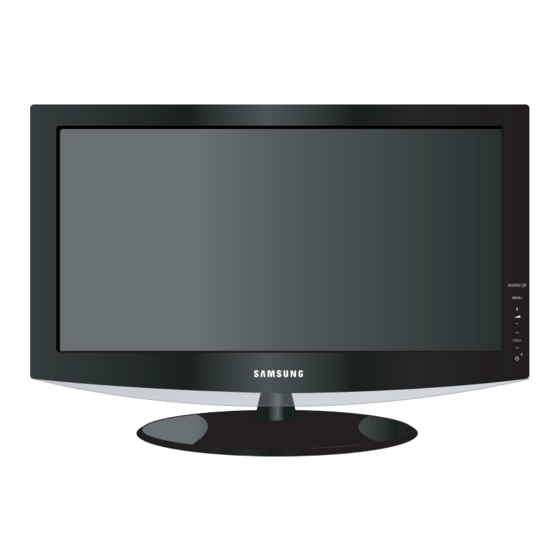
10 Operating Instructions and Installation 10 Operating Instructions and Installation 10-1 Front - The product color and shape may vary depending on the model. 1. SOURCE 5. SPEAKERS Toggles between all the available input sources (TV, AV1, AV2, S-Video 1, S-Video 2, Component1, (POWER) Component2, PC, HDMI1, HDMI2, HDMI3). -
Page 95: Connection Panel
10 Operating Instructions and Installation 10-2 Connection Panel [Side Panel Jacks] 1. AUDIO OUT 5. ANT 1 IN/ANT 2 IN Connect to the audio input jacks on your Amplifier/ Connect to an antenna or cable TV system. Home theater. 6. EX LINK 2. -
Page 96: Remote Control
10 Operating Instructions and Installation 10-3 Remote Control - This is a special remote control for the visually impaired, and has Braille points on the Power, Channel and Volume buttons. 10-3... - Page 97 10 Operating Instructions and Installation 1. POWER 19. When pressing this button, a number of buttons on Turns the TV on and off. the remote control (e.g. TV, DVD, STB, CABLE, 2. NUMERIC BUTTONS VCR, MUTE, VOL and CH buttons) light up for a few Press to change the channel.
-
Page 98: Disassembly And Reassembly
11 Disassembly and Reassembly 11 Disassembly and Reassembly This section of the service manual describes the disassembly and reassembly procedures for the TFT-LCD TV. WARNING : This monitor contains electrostatically sensitive devices. Use caution when handling these components. 11-1 Disassembly Cautions : 1. - Page 99 11 Disassembly and Reassembly Description Picture Description 2. Lift up the rear cover and remove the stand. 3. Remove Screws from the stand BRKT and lift up the stand BRKT. 11-2...
- Page 100 11 Disassembly and Reassembly Description Picture Description 4. Disconnect cable from the boards. 5.Remove screws from the board and lift up the speakers. 11-3...
- Page 101 11 Disassembly and Reassembly Description Picture Description 6.Remove screws from the panel BRKT and lift up the BRKT. 11-4...
-
Page 102: Reassembly
11 Disassembly and Reassembly 11-2 Reassembly Reassembly procedures are in the reverse order of disassembly procedures. 11-5... - Page 103 11 Disassembly and Reassembly Memo 11-6...
-
Page 104: Main Pcb Diagram
12 PCB Diagram 12 PCB Diagram 12-1 Main PCB Diagram 12-1... - Page 105 12 PCB Diagram 12-2-1 Power PCB Diagram(32" model) 12-2...
- Page 106 12 PCB Diagram 12-2-2 Power PCB Diagram(40" model) 12-3...
- Page 107 12 PCB Diagram Memo 12-4...
-
Page 108: Circuit Descriptions
13 Circuit Descriptions 13 Circuit Descriptions 13-1 Block description BLOCK DESCRIPTION REMARK LAKE2(IC1301) DTV dECODER + ARM CPU S4LF111 SVP-PX(IC1101) Video Decoder + Scaler STP03 FBE2(IC901) Image Backend Enhancer DNIe SDP64 Sub Micom(IC202) Comtrol Power,PANEL,etc. WT61P6S Sound IC(IC302) Sound Main Processor IC MSP4450 Sound AMP(IC401) Sound AMP IC... - Page 109 13 Circuit Descriptions Memo 13-2...
-
Page 110: Reference Infomation
14 Reference Infomation 14 Reference Infomation 14-1 Technical Terms - TFT-LCD - Image Lock (Thin film Transistor Liquid Crystal Display) This means "Fineness adjustment " in ADC(Analog to Digital Converter) LCD Monitor, the features are "Fine" and "Coarse" This is a circuit that converts from analog signal to digital signals. - Page 111 14 Reference Infomation - EDID - Resolution Extended Display Identification Data PC can The number of horizontal and vertical dots used recognize the monitor information as Product to compose the screen image is called 'resolution'. data, Product name,Display mode,Serial number This number shows the accuracy of the display.
- Page 112 - Channel Fine Tuning This feature allows the viewer to fine-tune the TV channel to obtain the best viewing conditions. The Samsung LCD TV has both automatic and manual channel fine-tuning features to enable the viewer to adjust their desired settings.
-
Page 113: Pin Assignments
14 Reference Infomation 14-2 Pin Assignments 14-2-1 DVI-D Sync Type 24P DVI-D Pin No. Rx2- DDC Input power (+5V) Rx2+ IDENT-DVI Output Signal (HDCP Control) Rx0- DDC - SCL Rx0+ DDC - SDA Rx1- Rx1+ RxC+ RxC- Figure 1. 14-4... - Page 114 14 Reference Infomation 14-2-2 Component 1, 2 14-2-3 S-Video Separate RCA Green Pb (Cb) RCA Blue Pr (Cr) RCA Red Audio L 14-2-5 D-SUB RCA White Separate Audio R RCA Red Green Blue 14-2-4 A/V 1,2 GND Red GND Green GND Blue RCA Yellow CVBS...
-
Page 115: Timing Chart
14 Reference Infomation 14-3 Timing Chart This section of the service manual describes the timing that the computer industry recognizes as standard for computer- generated video signals. 14-3-1 LCD Panel Mode1 mode 14-6... - Page 116 14 Reference Infomation 14-3-2 Supported Modes (1) 14-7...
- Page 117 14 Reference Infomation 14-3-3 Supported Modes (2) 14-8...
- Page 118 14 Reference Infomation 14-3-4 Supported Modes (3) 14-9...
- Page 119 14 Reference Infomation Memo 14-10...