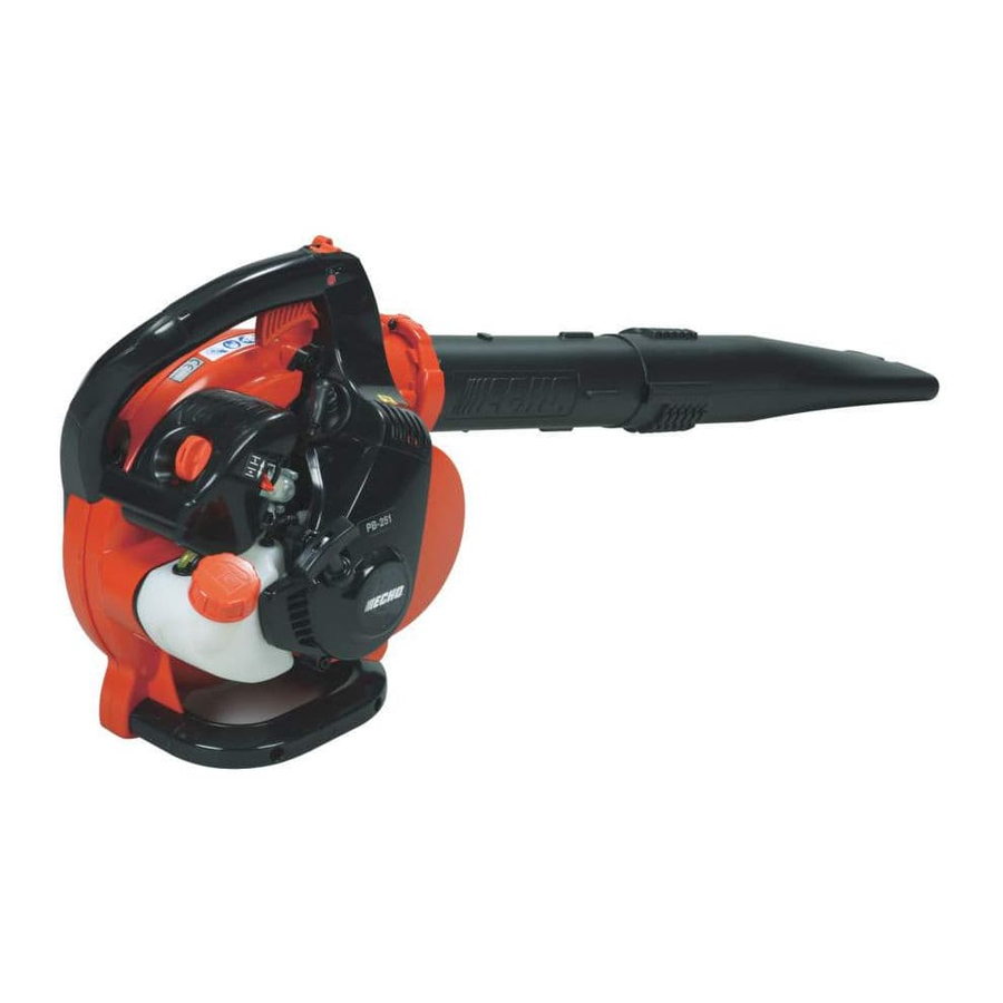
Echo PB-251 Service Manual
Hide thumbs
Also See for PB-251:
- Operator's manual (146 pages) ,
- Service data (8 pages) ,
- Parts catalog (32 pages)
Table of Contents
Advertisement
Advertisement
Table of Contents
Troubleshooting

Related Manuals for Echo PB-251


Summary of Contents for Echo PB-251
- Page 1 Ord. No. 403-16...
- Page 2 INTRODUCTION This service manual contains information for service and maintenance of ECHO POWER BLOWER, model PB-251. For systematic diagnosis, to avoid extra work and time loss, please refer to “Troubleshooting guide” that describes problems, testings, remedies and references. We recommend you make use of Operator’s Manual and Parts Catalog together with...
-
Page 3: Table Of Contents
PB-251 TABLE OF CONTENTS Page Page 1 SERVICE INFORMATION ........2 Adjusting carburetor ........29 Specifications ..........2 Testing carburetor ......... 31 Technical data ..........3 Checking crankcase pulse passage ..... 32 Torque limits ............ 4 Checking metering lever ....... 32 Special repairing materials ...... -
Page 4: Service Information
SERVICE INFORMATION PB-251 1 SERVICE INFORMATION 1-1 Specifications Dimensions Length* mm(in) 330 (13.0) Width* mm(in) 265 (10.4) Height mm(in) 360 (14.2) Dry weight** kg(lb) 4.5 (9.9) Engine Type KIORITZ, air-cooled, two-stroke, single cylinder Rotation Counterclockwise as viewed from the output end Displacement 25.4 (1.55) -
Page 5: Technical Data
PB-251 SERVICE INFORMATION 1-2 Technical data Engine Idling speed* 2800 - 3200 Wide open throttle speed* 6700 - 7200 Compression pressure MPa (kgf/cm ) (psi) 0.81 (8.3) (118) Ignition system Spark plug gap mm (in) 0.6 - 0.7 (0.024 - 0.028) -
Page 6: Torque Limits
Material Location Remarks Thread locking sealant Engine mount Loctite # 242, ThreeBond 1324 or equivalent Fun hub Starter pawl Loctite # 222, ThreeBond 1342 or equivalent Muffler cover Grease Rewind spring Lithium based grease or ECHO LUBE Starter center shaft... -
Page 7: Service Limits
PB-251 SERVICE INFORMATION 1-5 Service limits 5K204 5K263 5K264 5K265 5K016 5K017 5K267 5K266 5K219 5K171 Description mm (in) Cylinder bore When plating is worn and aluminum can be seen Piston outer diameter Min. 33.91 (1.335) Piston pin bore Max. -
Page 8: Special Tools
SERVICE INFORMATION PB-251 1-6 Special tools Key Part Number Description Used for: 897801-33330 Tachometer PET-1000 Measuring engine speed 897826-16131 Pressure plug Testing crankcase and cylinder sealings 897827-16131 Pressure plate Testing crankcase and cylinder sealings 897835-16131 Pressure connector Testing crankcase and cylinder sealings... -
Page 9: Starter System
PB-251 STARTER SYSTEM 2 STARTER SYSTEM ( A ) Pawl carrier ( B ) Starter pawl ( C ) Starter drum ( D ) Rewind spring ( E ) Starter case ( F ) Starter rope ( G ) Rope guide... - Page 10 STARTER SYSTEM PB-251 2-1 Removing starter drum and rope (continued) 3. Pull out starter rope about 30 centimeters (12in) and hold starter drum with finger. 4. Pull out starter rope in starter case. 5. Rotate starter drum clockwise to releace tension of rewind spring with the rope hooked at notch (A).
-
Page 11: Installing Rewind Spring
PB-251 STARTER SYSTEM 2-2 Installing rewind spring Use of eye protection and safety gloves are strongly recommended while working on re- wind spring. If rewind spring unwinds unexpectedly, follow steps 1) to 4). 1) Wind rewind spring by hand. Then draw out the end of spring (A) as shown. -
Page 12: Installing Starter Drum And Rope
STARTER SYSTEM PB-251 2-3 Installing starter drum and rope 1. When installing new starter rope, singe both ends of rope to prevent fraying. WARNING DANGER Do not use flame in an area where gasoline is stored or flammable gases may exist. -
Page 13: Increasing Rope Tension
PB-251 STARTER SYSTEM 2-4 Increasing rope tension 1. Pre-tension rewind spring by rotating starter drum counterclockwise three turns with starter rope hooked at notch (A). 2. Hold starter drum to prevent it from rewinding, and pull starter grip, to take up the slack of rope. - Page 14 STARTER SYSTEM PB-251 2-5 Replacing starter pawl (continued) 5. Remove pawl carrier counterclockwise with 6mm L hexagonal wrench 895615-10860. 6. Remove E-ring(s) (A) from starter pawl(s). 7. Insert (new) spring(s) (B) to (new) starter pawl(s), and push starter pawl(s) into the hole(s). Then, install E-ring(s) as shown.
-
Page 15: Ignition System
PB-251 IGNITION SYSTEM 3 IGNITION SYSTEM ( A ) Ignition switch ( B ) Lead terminal ( C ) Ignition switch knob ( D ) Stop lead ( E ) Stop lead grommet ( F ) Spark plug ( G ) Spark plug cap coil... -
Page 16: Troubleshooting Guide
IGNITION SYSTEM PB-251 Troubleshooting guide Start Remedy Check Clean / Regap / Replace S.T. spark plug. Adjust pole shoe air gaps. Pole (Check flywheel magnet shoe air Clean / at the same time. Go to gaps Regap / Spark plug S.T. -
Page 17: Testing Spark
PB-251 IGNITION SYSTEM 3-2 Testing spark WARNING DANGER Do not touch the spark plug while perform- ing the test to avoid receiving electric shock. WARNING DANGER Do not check the spark in an area where gaso- line is spilled or flammable gases may exist. -
Page 18: Replacing Spark Plug Cap And Coil
IGNITION SYSTEM PB-251 3-4 Replacing spark plug cap and coil 1. Disconnect spark plug cap from spark plug. Remove spark plug cap cover from spark plug cap. 2. Apply some oil in spark plug cap (A) to aid in removing spark plug cap from high tension lead (B). -
Page 19: Checking Ignition Switch
PB-251 IGNITION SYSTEM 3-6 Checking ignition switch 1. Remove air cleaner cover and handle lid. 2. Disconnect all lead couplers in handle. 3. Connect probes of an ohm-meter or a multimeter to ignition switch leads as shown. 4. When ignition switch is in RUN position, tester should indicate infinite resistance. - Page 20 IGNITION SYSTEM PB-251 3-7 Replacing ignition switch (continued) 5. Insert lead terminal (C) in the hole of handle. 6. Slot new ignition switch (E) into lead terminal as shown. 7. Connect all couplers and lead terminal. Route leads around ribs and in grooves in handle (refer to “4-2 Reassembling handle and throttole control”).
-
Page 21: Replacing Ignition Coil
PB-251 IGNITION SYSTEM 3-8 Replacing ignition coil 1. Remove stop lead grommet (A) and high tension lead grommet (B) from cylinder cover. 2. Remove ignition coil (C) from cylinder. 3. Pull out stop lead (D) from ignition coil. 4. Remove high tension lead (E) from cylinder cover, and then remove spark plug cap and spark plug cap cover from high tension lead. - Page 22 IGNITION SYSTEM PB-251 3-10 Checking flywheel and key (continued) 4. Remove spark plug, and then insert piston stopper 897537-30130 (A) by hand. 5. Remove fan hub counterclockwise with socket wrench, and then remove flywheel. If flywheel cannot be lifted off, follow steps 6 to 8.
-
Page 23: Handle And Control System
PB-251 HANDLE AND CONTROL SYSTEM 4 HANDLE AND CONTROL SYSTEM ( A ) Handle lid ( B ) Throttle trigger ( C ) Throttle rod ( D ) Throttle cover ( E ) Ignition switch ( F ) Ground lead... -
Page 24: Disassembling Handle And Throttle Control
HANDLE AND CONTROL SYSTEM PB-251 4-1 Disassembling handle and throttle control 1. Remove air cleaner cover and muffler cover. 2. Remove screw (A: M5x20) in order to remove handle lid. 3. Remove screw (B: M5x25) and screw (C: M5x20). Remove handle lid. -
Page 25: Reassembling Handle And Throttle Control
PB-251 HANDLE AND CONTROL SYSTEM 4-1 Disassembling handle and throttle control (continued) 7. Pull out throttle rod end (F) from throttle trigger (G). Remove another throttle rod end (H) from ball end (I) of throttle cable. 8. Remove throttle trigger (G) from throttle trigger post (J). - Page 26 HANDLE AND CONTROL SYSTEM PB-251 4-2 Reassembling handle and throttle control (continued) 3. Install throttle trigger (F) onto throttle trigger post (G) as shown. 4. Hook the ball end (H) of throttle cable in the end of throttle rod. Then insert the other throttle rod end (I) into the hole of throttle trigger.
-
Page 27: Fuel System
PB-251 FUEL SYSTEM 5 FUEL SYSTEM ( A ) Air cleaner cover ( B ) Air filter ( C ) Prevent plate ( D ) Air cleaner case ( E ) Throttle bracket ( F ) Carburetor ( G ) Intake insulator... -
Page 28: Cleaning Air Filter
FUEL SYSTEM PB-251 5-1 Cleaning air filter 1. Close choke shutter and remove air cleaner cover and air filter. 2. Clean air cleaner cover and air filter with com- pressed air or wash air filter in a suitable cleaning solvent. Air filter should be dried completely after washing. -
Page 29: Checking Fuel Tank And Tank Vent
PB-251 FUEL SYSTEM 5-3 Checking fuel tank and tank vent 1. Disconnect black fuel line from carburetor and connect pressure tester 897803-30133 to fuel line by joint pipe V186-000020 (A). 2. Pinch tank vent line (B) with longnose pliers to block air passage. -
Page 30: Replacing Fuel Line, Tank Vent Line And Grommet
FUEL SYSTEM PB-251 5-4 Replacing fuel line, tank vent line and grommet 1. Disconnect fuel lines from carburetor. 2. Remove fuel line grommet (A) together with fuel lines. Fuel strainer can be directly pulled out through grommet hole. 3. Remove fuel strainer from fuel line. -
Page 31: Adjusting Carburetor
PB-251 FUEL SYSTEM 5-5 Adjusting carburetor GENERAL ADJUSTMENT RULES: Before starting the unit for adjustment, check the following items. a. Correct spark plug must be clean and properly gapped. b. Air filter must be clean and properly installed. c. Muffler exhaust port must be clear of carbon. - Page 32 FUEL SYSTEM PB-251 5-5 Adjusting carburetor (Continued) NOTE : The initial carburetor settings for idle adjust screw, idle and H mixture needles are intended to start and run the engine before final carburetor ad- justments are made to conform the unit to meet Emission Regulations.
-
Page 33: Testing Carburetor
PB-251 FUEL SYSTEM 5-6 Testing carburetor 1. Remove air cleaner cover. Push purge bulb sev- eral times to fill and wet fuel pump circuit with fuel. 2. Pull off black fuel line (A) from carburetor and connect pressure tester 897803-30133 (C) to fuel inlet of carburetor. -
Page 34: Checking Crankcase Pulse Passage
FUEL SYSTEM PB-251 5-7 Checking crankcase pulse passage 1. Remove carburetor and drop a little oil in pulse hole (A) on intake insulator. 2. Remove spark plug and pull starter grip several times. Oil should spit back from the hole. -
Page 35: Checking Inlet Needle Valve
PB-251 FUEL SYSTEM 5-9 Checking inlet needle valve 1. Remove metering lever (A) and its pin. Remove spring (B) and inlet needle valve (C). 2. Inspect inlet needle valve if worn or sticky. Clean or replace as required. NOTE: Causes of the fuel flooding from carburetor to cylinder are as follows: - Improper assembling of metering lever and spring. -
Page 36: Replacing Carburetor
FUEL SYSTEM PB-251 5-11 Replacing carburetor 1. Remove carburetor. 2. Rotate throttle valve (A) clockwise by finger, until swivel (B) touches boss (C). 3. Push ball end (D) of throttle cable to move the other throttle cable end (E) from swivel (B). - Page 37 PB-251 FUEL SYSTEM 5-11 Replacing carburetor (continued) 5. Use 10mm spanner (F) and remove throttle bracket (G) and nut (H) from old carburator. 6. Install nut (H) into boss (I) of new carburetor (J). 7. Apply thread locking sealant (Loctite #242, ThreeBond 1324 or equivarent) on threads (K, L) of throttle bracket (G).
- Page 38 FUEL SYSTEM PB-251 5-11 Replacing carburetor (continued) 11. If groove of throttle bracket overrun the corner of carburetor, screw in throttle bracket clockwise and meet groove to the corner of carbretor. NOTE: Do not turn the throttle bracket out counter- clockwise, because throttle bracket may come loose over time.
-
Page 39: Blower System
PB-251 BLOWER SYSTEM 6 BLOWER SYSTEM ( A ) Fan case grid ( B ) Outer fan case ( C ) Fan ( D ) Inner fan case ( E ) Bolwer pipe fixture... -
Page 40: Disassembling Fan And Fan Case
BLOWER SYSTEM PB-251 6-1 Disassembling fan and fan case 1. Remove blower pipes, blower pipe fixtures, air clener cover and handle lid. 2. Remove seven screws and remove outer fan case. 3. Remove spark plug cap and clean out dirt around spark plug. -
Page 41: Engine
PB-251 ENGINE 7 ENGINE ( A ) Cylinder cover (plastic) ( B ) Cylinder cover (metal) ( C ) Cylinder ( D ) Cylinder gasket ( E ) Piston ring ( F ) Piston ( G ) Piston pin ( H ) Snap ring... -
Page 42: Testing Cylinder Compression
ENGINE PB-251 7-1 Testing cylinder compression NOTE: Test cylinder compression when engine is cold. 1. Set ignition switch to STOP position and remove spark plug. 2. Install compression gauge in cylinder spark plug hole as shown and pull starter several times to sta- bilize reading. -
Page 43: Checking Muffler And Exhaust Port
PB-251 ENGINE 7-2 Cleaning cooling air passages (continued) 3. Remove spark plug cap and clean dirt around spark plug. Remove spark plug. 4. Install piston stopper 897537-30130 (D) in the spark plug hole by hand to stop crankshaft rotation. 5. Remove pawl carrier (B) counterclockwise with 6mm L hexagonal wrench 895615-10860. -
Page 44: Testing Crankcase And Cylinder Sealings
ENGINE PB-251 7-3 Checking muffler and exhaust port (continued) 3. Remove holders (B), gasket (A), and screen (C, if present) from muffler. 4. Remove carbon deposits from screen, muffler, and other component parts. If heavily deposited, replace with new parts as required. -
Page 45: Replacing Oil Seal
PB-251 ENGINE 7-5 Replacing oil seal 1. Pry defective oil seal(s) from engine. 2. Lubricate a new oil seal on its circumference with lubricant and push it in using an oil seal tool 897726-16431 (A). NOTE: Since oil seal on starter side should be lo- cated at 1 to 1.5 mm (0.04 to 0.06 in) deeper than... -
Page 46: Checking Piston And Piston Ring
ENGINE PB-251 7-7 Checking piston and piston ring 1. Clean piston crown with fine sandpaper or wooden scraper as required. 2. After removing piston ring, clean piston ring groove using ring groove cleaning tool. NOTE: Do not use square end of broken piston ring when cleaning piston ring groove, otherwise, piston ring groove might be damaged. -
Page 47: Disassembling Crankcase
PB-251 ENGINE 7-9 Disassembling crankcase 1. Remove three crankcase screws. 2. Hold crankcase and tap crankshaft end using plastic mallet to separate crankcase halves. NOTE: To avoid crankcase damage, use 0.5kg (1 lb) plastic mallet and minimum force to drive it out. -
Page 48: Assembling Crankshaft And Crankcase
ENGINE PB-251 7-11 Assembling crankshaft and crankcase 1. Clean mating surface of each crankcase half. 2. Insert crankshaft starter end into starter side of crankcase half until properly seated. If hard to in- sert, preheat ball bearing using floodlight or suitable heater for easier installation. -
Page 49: Installing Piston Ring And Cylinder
PB-251 ENGINE 7-13 Installing piston ring and cylinder 1. Hold new cylinder gasket on cylinder base with Loctite #222, ThreeBond 1324 or equivalent for easier installation of cylinder. 2. Install piston ring on piston ensuring that locating pin (A) is positioned between ring ends. -
Page 50: Installing Engine To Inner Fan Case
ENGINE PB-251 7-14 Installing engine to inner fan case 1. Install flywheel and fan hub to crankshaft (reffer to “3-10 Checking flywheel and key”). Set pole shoe air gaps (reffer to “3-9 Setting pole shoe air gaps”). 2. Install pawl carrier spacer (A) and pawl carrier to engine (reffer to “2-5 Replacing starter pawl”). -
Page 51: Maintenance Guide
PB-251 MAINTENANCE GUIDE 8-1 Service intervals Intervals 3 months 6 months Check point Service Reference Daily 100 hours 300 hours Screws, bolts, and nuts Inspect / Retighten / Replace Air filter Clean Inspect / Replace Carburetor Inspect / Replace 5-6, 5-10, 5-11... -
Page 52: Troubleshooting Guide
MAINTENANCE GUIDE PB-251 8 MAINTENANCE GUIDE 8-2 Troubleshooting guide TROUBLE Engine does not crank. Engine does not start. Fuel leaks. Idling is not stable. Acceleration is poor. Engine stalls at high speed. Engine lacks power. Engine overheats. Engine misfires. Engine / others are extremely noisy. - Page 53 PB-251 MAINTENANCE GUIDE 8-2 Troubleshooting guide (Continued) CHECKING REFERENCES Check first. Fuel system / Carburetor 13 12 11 10 09 08 07 06 05 04 03 02 01 Air filter Fuel cap / strainer Fuel tank / vent / pipe...
-
Page 54: Disassembly Chart
MAINTENANCE GUIDE PB-251 8-3 Disassembly chart Air cleaner Outer fan Starter Muffler Handle lid cover case assembly cover (4-1) (5-1) (6-1) (2-1) Ignition Pawl Handle switch carrier (4-1) (6-1) (3-7) (2-5) Throttle Air filter Engine control (5-1) cover (4-1) Fuel tank... -
Page 55: Index
PB-251 INDEX Adapter, piston pin tool 44, 46 High tension lead 16 Pressure plate 6, 42 Air filter 26, 49 Idle mixture needle 3, 29, 30 Pressure plug 6, 42 Idle adjust screw 3, 29, 30 Pressure tester 6, 27, 31, 42... - Page 56 Printed in Japan 0705 TOKYO JAPAN...