Table of Contents
Advertisement
MCAC-VTSM-2014-04
R410A DC Inverter VRF V4 Plus Individual Series 50Hz
Part 1 General Information
1. Product lineup ........................................................................................... 2
2. Nomenclature ........................................................................................... 3
3. Features ................................................................................................... 4
4. Indoor units lineup .................................................................................... 9
General Information
1
Advertisement
Table of Contents
Troubleshooting

Related Manuals for Midea VRF V4 Plus I Series


Summary of Contents for Midea VRF V4 Plus I Series
- Page 1 MCAC-VTSM-2014-04 R410A DC Inverter VRF V4 Plus Individual Series 50Hz Part 1 General Information 1. Product lineup ................... 2 2. Nomenclature ................... 3 3. Features ....................4 4. Indoor units lineup ..................9 General Information...
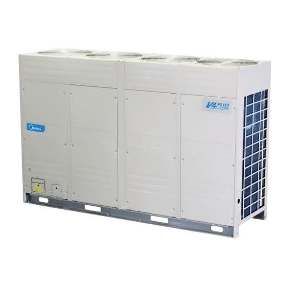
- Page 2 MCAC-VTSM-2014-04 R410A DC Inverter VRF V4 Plus Individual Series 50Hz 1. Product lineup 380-415V/3Ph/50Hz Model name External appearance MDV-730W/DRN1-i(C) MDV-785W/DRN1-i(C) MDV-850W/DRN1-i(C) MDV-900W/DRN1-i(C) Outdoor units basic information Net dimension Net/Gross Max. quantity of Model W×H×D (mm) weight (kg) connectable indoor units MDV-730W/DRN1-i(C) 2540×1615×765 555/590...
- Page 3 2. Nomenclature MDV – 730 W / D R N1 – i (C) Series code i: Individual type Refrigerant type N1: R410A Power supply R: 380-415V, 3Ph, 50Hz D: DC inverter type W: Outdoor units Cooling capacity (×100W) Midea General Information...
- Page 4 In case the outdoor unit is located below the indoor unit the height difference between outdoor unit and indoor unit is up to 90m. The longest piping length is 40m standard. It can be extended to 90m*. *For more information, please contact your local Midea dealer. General Information...
- Page 5 40 Pa High static pressure propeller and optimized fan guard can adapt to various installation environments. Midea now offers 40Pa* external pressure for customized applications. A standard 0-20Pa function is equipped by default 3.2 High efficiency 3.2.1 High efficiency DC inverter compressor High efficiency DC inverter compressor reduces power consumption by 25%.
- Page 6 3.3.2 Night silent operation mode Midea's Night Silent Mode feature which is easily set on the PCB board allows the unit to be set to vary time options during Non-Peak and Peak operation time optimizing the units noise output.
- Page 7 MCAC-VTSM-2014-04 R410A DC Inverter VRF V4 Plus Individual Series 50Hz 3.4 Easy installation and service 3.4.1 Compact design for effective use of space Easy to transport Compact size and light weight design minimizes the installation footprint, reduces the installation floor load, and easier for transportation.
- Page 8 MCAC-VTSM-2014-04 R410A DC Inverter VRF V4 Plus Individual Series 50Hz 3.4.4 Auto addressing Outdoor unit can distribute address for each indoor unit automatically. Wireless and wired controllers can enquire and modify each indoor unit’s address. 3.4.5 Easy maintenance Reserved checking window on electric control box for convenient spot checking and status enquiry.
- Page 9 MCAC-VTSM-2014-04 R410A DC Inverter VRF V4 Plus Individual Series 50Hz 4. Indoor units lineup Cassette type One-way cassette Two-way cassette Compact four-way cassette Four-way cassette Capacity (×100W) ● ● ● ● ● ● ● ● ● ● ● ● ● ●...
- Page 10 MCAC-VTSM-2014-04 R410A DC Inverter VRF V4 Plus Individual Series 50Hz Indoor units lineup Floor-standing/Ceiling & Floor/Console Cased floor-standing Uncased floor-standing Ceiling & floor console Capacity (×100W) ● ● ● ● ● ● ● ● ● ● ● ● ● ● ●...
- Page 11 MCAC-VTSM-2014-04 R410A DC Inverter VRF V4 Plus Individual Series 50Hz Part 2 Specifications & Performances 1. Specifications ..................12 2. Dimensions ..................... 14 3. Service space ..................15 4. Piping diagrams ..................17 5. Wiring diagrams and field wiring ............. 19 6.
- Page 12 R410A DC Inverter VRF V4 Plus Individual Series 50Hz MCAC-VTSM-2014-04 1. Specifications Model MDV-730W/DRN1-i(C) MDV-785W/DRN1-i(C) MDV-850W/DRN1-i(C) MDV-900W/DRN1-i(C) Power supply V-Ph-Hz 380-415/3/50 380-415/3/50 380-415/3/50 380-415/3/50 Capacity 73.0 78.5 85.0 90.0 Power input 22.3 24.2 28.3 28.5 Cooling 3.27 3.24 3.00 3.16 Capacity 81.5 87.5...
- Page 13 MCAC-VTSM-2014-04 R410A DC Inverter VRF V4 Plus Individual Series 50Hz Material ASG20 ASG20 ASG20 ASG20 Type Axial fan Axial fan Axial fan Axial fan Quantity Outdoor Diameter 562/560 562/560 562/560 562/560 Height 162/189 162/189 162/189 162/189 0-20 (default) 0-20 (default) 0-20 (default) 0-20 (default) External static...
- Page 14 R410A DC Inverter VRF V4 Plus Individual Series 50Hz MCAC-VTSM-2014-04 2. Dimensions MDV-730W/DRN1-i(C), MDV-785W/DRN1-i(C), MDV-850W/DRN1-i(C), MDV-900W/DRN1-i(C) Specifications & Performances...
- Page 15 MCAC-VTSM-2014-04 R410A DC Inverter VRF V4 Plus Individual Series 50Hz 3. Service space Ensure enough space for maintenance. The modules in the same system must be on the same height. When the outdoor unit is higher than the surrounding obstacle One row Two rows Specifications &...
- Page 16 R410A DC Inverter VRF V4 Plus Individual Series 50Hz MCAC-VTSM-2014-04 More than two rows When the outdoor unit is lower than the surrounding obstacle, refer to the layout used when the outdoor unit is higher than the surrounding obstacle. However, to avoid cross connection of the outdoor hot air from affecting the heat exchange effect, please add an air director onto the exhaust hood of the outdoor unit to facilitate heat dissipation.
- Page 17 MCAC-VTSM-2014-04 R410A DC Inverter VRF V4 Plus Individual Series 50Hz 4. Piping diagrams EXVB 26-28HP EXVA 30-32HP EXVB EXVA Specifications & Performances...
- Page 18 R410A DC Inverter VRF V4 Plus Individual Series 50Hz MCAC-VTSM-2014-04 Key components: Oil separator: It is used to separate oil from high pressure and high temperature gas refrigerant, which is pumped out from compressor. The separation efficiency is up to 99%, it makes the oil return back to each compressor very soon.
- Page 19 MCAC-VTSM-2014-04 R410A DC Inverter VRF V4 Plus Individual Series 50Hz 5. Wiring diagrams and field wiring Specifications & Performances...
- Page 20 R410A DC Inverter VRF V4 Plus Individual Series 50Hz MCAC-VTSM-2014-04 6. Field wiring The control line should be shielded wire. Using other wiring shall create signal interference, thus leading to error operation. The shielded nets at the two sides of shielded wires are either grounded to the earth, or connected with each other and jointed to the sheet metal along to the earth.
- Page 21 MCAC-VTSM-2014-04 R410A DC Inverter VRF V4 Plus Individual Series 50Hz Power(380-415V, 50Hz) Specifications & Performances...
- Page 22 R410A DC Inverter VRF V4 Plus Individual Series 50Hz MCAC-VTSM-2014-04 7. Electric characteristics Units Power supply Compressor Model Voltage Min. TOCA RLA (A) 15.62+ 0.52×2+0 3.6×2+ MDV-730W/DRN1-i(C) 380~415 55.7 9.8×3 .38×2 2.7×2 15.62+ 0.52×2+0 3.6×2+ MDV-785W/DRN1-i(C) 380~415 58.4 71.5 9.8×3 .38×2 2.7×2 15.62+...
- Page 23 MCAC-VTSM-2014-04 R410A DC Inverter VRF V4 Plus Individual Series 50Hz 8. Capacity tables MDV-730W/DRN1-i(C) 8.1 Cooling capacity Outdoo Indoor temperature( C DB/WD) Combinatio 20.8/14 23.3/16 25.8/18 27/19 28.2/20 30.7/22 32/24 n (%) temp. 64.1 9.11 76.3 11.1 88.6 11.9 92.0 12.4 96.4 12.7...
- Page 24 R410A DC Inverter VRF V4 Plus Individual Series 50Hz MCAC-VTSM-2014-04 MDV-730W/DRN1-i(C) Outdoo Indoor temperature( C DB/WD) Combinatio 20.8/14 23.3/16 25.8/18 27/19 28.2/20 30.7/22 32/24 n (%) temp. 54.2 7.69 64.6 9.57 75.0 11.4 80.3 12.2 85.5 13.1 92.0 13.7 94.1 14.1 54.2 7.84...
- Page 25 MCAC-VTSM-2014-04 R410A DC Inverter VRF V4 Plus Individual Series 50Hz MDV-730W/DRN1-i(C) Outdoo Indoor temperature( C DB/WD) Combinatio 20.8/14 23.3/16 25.8/18 27/19 28.2/20 30.7/22 32/24 n (%) temp. 44.3 6.19 52.9 7.43 61.5 8.76 65.7 9.56 69.8 10.1 78.4 11.7 87.0 13.4 44.3 6.25...
- Page 26 R410A DC Inverter VRF V4 Plus Individual Series 50Hz MCAC-VTSM-2014-04 MDV-730W/DRN1-i(C) Outdoo Indoor temperature( C DB/WD) Combinatio 20.8/14 23.3/16 25.8/18 27/19 28.2/20 30.7/22 32/24 n (%) temp. 34.4 4.87 41.1 5.71 47.7 6.47 51.1 6.94 54.4 7.41 61.0 8.47 67.7 9.74 34.4 4.91...
- Page 27 MCAC-VTSM-2014-04 R410A DC Inverter VRF V4 Plus Individual Series 50Hz MDV-730W/DRN1-i(C) Indoor temperature( C DB/WD) Outdoor Combination 20.8/14 23.3/16 25.8/18 27/19 28.2/20 30.7/22 32/24 temp. 24.64 3.61 29.46 4.17 34.15 4.79 36.50 5.02 38.85 5.30 43.54 6.02 48.49 6.49 24.64 3.63 29.46 4.26...
- Page 28 R410A DC Inverter VRF V4 Plus Individual Series 50Hz MCAC-VTSM-2014-04 MDV-785W/DRN1-i(C) Indoor temperature( C DB/WD) Outdoor Combinatio 20.8/14 23.3/16 25.8/18 27/19 28.2/20 30.7/22 32/24 temp. n (%) 68.9 9.89 82.1 12.0 95.3 12.9 98.9 13.4 103.7 13.8 106.2 15.0 108.9 15.1 68.9 9.89...
- Page 29 MCAC-VTSM-2014-04 R410A DC Inverter VRF V4 Plus Individual Series 50Hz MDV-785W/DRN1-i(C) Outdoo Indoor temperature( C DB/WD) Combinatio 20.8/14 23.3/16 25.8/18 27/19 28.2/20 30.7/22 32/24 n (%) temp. 58.3 8.34 69.5 10.3 80.7 12.3 86.3 13.3 91.9 14.3 98.9 14.8 101.2 15.3 58.3 8.50...
- Page 30 R410A DC Inverter VRF V4 Plus Individual Series 50Hz MCAC-VTSM-2014-04 MDV-785W/DRN1-i(C) Outdoo Indoor temperature( C DB/WD) Combinatio 20.8/14 23.3/16 25.8/18 27/19 28.2/20 30.7/22 32/24 n (%) temp. 47.6 6.72 56.9 8.06 66.1 9.51 70.6 10.3 75.1 11.0 84.3 12.7 93.6 14.5 47.6 6.78...
- Page 31 MCAC-VTSM-2014-04 R410A DC Inverter VRF V4 Plus Individual Series 50Hz MDV-785W/DRN1-i(C) Outdoo Indoor temperature( C DB/WD) Combinatio 20.8/14 23.3/16 25.8/18 27/19 28.2/20 30.7/22 32/24 n (%) temp. 37.0 5.29 44.3 6.20 51.3 7.02 54.9 7.53 58.5 8.04 65.6 9.20 72.8 10.5 37.0 5.33...
- Page 32 R410A DC Inverter VRF V4 Plus Individual Series 50Hz MCAC-VTSM-2014-04 MDV-785W/DRN1-i(C) Indoor temperature( C DB/WD) Outdoor Combination 20.8/14 23.3/16 25.8/18 27/19 28.2/20 30.7/22 32/24 temp. 26.49 3.92 31.68 4.53 36.73 5.20 39.25 5.45 41.77 5.75 46.82 6.54 52.15 7.04 26.49 3.94 31.68 4.62...
- Page 33 MCAC-VTSM-2014-04 R410A DC Inverter VRF V4 Plus Individual Series 50Hz MDV-850W/DRN1-i(C) Outdoo Indoor temperature( C DB/WD) Combinatio 20.8/14 23.3/16 25.8/18 27/19 28.2/20 30.7/22 32/24 n (%) temp. 74.6 11.5 88.9 14.1 103.2 15.1 107.1 15.7 112.3 16.2 115.0 17.6 117.9 17.7 74.6 11.5...
- Page 34 R410A DC Inverter VRF V4 Plus Individual Series 50Hz MCAC-VTSM-2014-04 MDV-850W/DRN1-i(C) Outdoo Indoor temperature( C DB/WD) Combinatio 20.8/14 23.3/16 25.8/18 27/19 28.2/20 30.7/22 32/24 n (%) temp. 63.1 9.76 75.2 12.1 87.4 14.4 93.5 15.5 99.5 16.7 107.1 17.3 109.6 17.9 63.1 9.94...
- Page 35 MCAC-VTSM-2014-04 R410A DC Inverter VRF V4 Plus Individual Series 50Hz MDV-850W/DRN1-i(C) Outdoo Indoor temperature( C DB/WD) Combinatio 20.8/14 23.3/16 25.8/18 27/19 28.2/20 30.7/22 32/24 n (%) temp. 51.6 7.86 61.6 9.43 71.6 11.1 76.5 12.1 81.3 12.9 91.3 14.8 101.3 17.0 51.6 7.93...
- Page 36 R410A DC Inverter VRF V4 Plus Individual Series 50Hz MCAC-VTSM-2014-04 MDV-850W/DRN1-i(C) Outdoo Indoor temperature( C DB/WD) Combinatio 20.8/14 23.3/16 25.8/18 27/19 28.2/20 30.7/22 32/24 n (%) temp. 40.0 6.18 47.9 7.25 55.5 8.21 59.5 8.81 63.4 9.40 71.0 10.7 78.9 12.3 40.0 6.23...
- Page 37 MCAC-VTSM-2014-04 R410A DC Inverter VRF V4 Plus Individual Series 50Hz MDV-850W/DRN1-i(C) Indoor temperature( C DB/WD) Outdoor Combination 20.8/14 23.3/16 25.8/18 27/19 28.2/20 30.7/22 32/24 temp. 28.69 4.58 34.30 5.30 39.77 6.08 42.50 6.37 45.23 6.72 50.70 7.64 56.47 8.24 28.69 4.61 34.30 5.40...
- Page 38 R410A DC Inverter VRF V4 Plus Individual Series 50Hz MCAC-VTSM-2014-04 MDV-900W/DRN1-i(C) TC: Total Capacity (kW); PI: Power Input (kW) (Compressor + Outdoor fan motor) Outdoo Indoor temperature( C DB/WD) Combinatio 20.8/14 23.3/16 25.8/18 27/19 28.2/20 30.7/22 32/24 n (%) temp. 79.0 11.6 94.1...
- Page 39 MCAC-VTSM-2014-04 R410A DC Inverter VRF V4 Plus Individual Series 50Hz MDV-900W/DRN1-i(C) TC: Total Capacity (kW); PI: Power Input (kW) (Compressor + Outdoor fan motor) Outdoo Indoor temperature( C DB/WD) Combinatio 20.8/14 23.3/16 25.8/18 27/19 28.2/20 30.7/22 32/24 n (%) temp. 66.8 9.82 79.7...
- Page 40 R410A DC Inverter VRF V4 Plus Individual Series 50Hz MCAC-VTSM-2014-04 MDV-900W/DRN1-i(C) TC: Total Capacity (kW); PI: Power Input (kW) (Compressor + Outdoor fan motor) Outdoo Indoor temperature( C DB/WD) Combinatio 20.8/14 23.3/16 25.8/18 27/19 28.2/20 30.7/22 32/24 n (%) temp. 54.6 7.91 65.2...
- Page 41 MCAC-VTSM-2014-04 R410A DC Inverter VRF V4 Plus Individual Series 50Hz MDV-900W/DRN1-i(C) TC: Total Capacity (kW); PI: Power Input (kW) (Compressor + Outdoor fan motor) Outdoo Indoor temperature( C DB/WD) Combinatio 20.8/14 23.3/16 25.8/18 27/19 28.2/20 30.7/22 32/24 n (%) temp. 42.4 6.22 50.7...
- Page 42 R410A DC Inverter VRF V4 Plus Individual Series 50Hz MCAC-VTSM-2014-04 MDV-900W/DRN1-i(C) TC: Total Capacity (kW); PI: Power Input (kW) (Compressor + Outdoor fan motor) Indoor temperature( C DB/WD) Outdoor Combination 20.8/14 23.3/16 25.8/18 27/19 28.2/20 30.7/22 32/24 temp. 30.38 4.61 36.32 5.33 42.11...
- Page 43 MCAC-VTSM-2014-04 R410A DC Inverter VRF V4 Plus Individual Series 50Hz 8.2 Heating capacity MDV-730W/DRN1-i(C) Indoor temperature(° C WB) Outdoor Air temperature ° C DB ° C WB -13.7 57.95 16.29 57.70 17.23 57.44 18.17 57.44 18.62 57.18 19.10 57.18 20.04 -11.8 60.29 17.01...
- Page 44 R410A DC Inverter VRF V4 Plus Individual Series 50Hz MCAC-VTSM-2014-04 MDV-730W/DRN1-i(C) TC: Total Capacity (kW); PI: Power Input (kW) (Compressor + Outdoor fan motor) Indoor temperature(° C WB) Outdoor Air Combination temperature ° C DB ° C WB -13.7 57.18 20.06 56.92 20.79...
- Page 45 MCAC-VTSM-2014-04 R410A DC Inverter VRF V4 Plus Individual Series 50Hz MDV-730W/DRN1-i(C) TC: Total Capacity (kW); PI: Power Input (kW) (Compressor + Outdoor fan motor) Indoor temperature(° C WB) Outdoor Air Combination temperature ° C DB ° C WB -13.7 56.27 23.86 56.02 24.37...
- Page 46 R410A DC Inverter VRF V4 Plus Individual Series 50Hz MCAC-VTSM-2014-04 MDV-785W/DRN1-i(C) TC: Total Capacity (kW); PI: Power Input (kW) (Compressor + Outdoor fan motor) Indoor temperature(° C WB) Outdoor Air Combinatio temperature n (%) ° C DB ° C WB -13.7 62.22 17.72...
- Page 47 MCAC-VTSM-2014-04 R410A DC Inverter VRF V4 Plus Individual Series 50Hz MDV-785W/DRN1-i(C) TC: Total Capacity (kW); PI: Power Input (kW) (Compressor + Outdoor fan motor) Indoor temperature(° C WB) Outdoor Air Combination temperature ° C DB ° C WB -13.7 61.39 21.82 61.11 22.60...
- Page 48 R410A DC Inverter VRF V4 Plus Individual Series 50Hz MCAC-VTSM-2014-04 MDV-785W/DRN1-i(C) TC: Total Capacity (kW); PI: Power Input (kW) (Compressor + Outdoor fan motor) Indoor temperature(° C WB) Outdoor Air Combination temperature ° C DB ° C WB -13.7 60.42 25.95 60.14 26.50...
- Page 49 MCAC-VTSM-2014-04 R410A DC Inverter VRF V4 Plus Individual Series 50Hz MDV-850W/DRN1-i(C) TC: Total Capacity (kW); PI: Power Input (kW) (Compressor + Outdoor fan motor) Indoor temperature(° C WB) Outdoor Air Combinatio temperature n (%) ° C ° C -13.7 67.55 20.5 67.26 21.7...
- Page 50 R410A DC Inverter VRF V4 Plus Individual Series 50Hz MCAC-VTSM-2014-04 MDV-850W/DRN1-i(C) TC: Total Capacity (kW); PI: Power Input (kW) (Compressor + Outdoor fan motor) Indoor temperature(° C WB) Outdoor Air Combination temperature ° C DB ° C WB -13.7 66.65 25.32 66.35 26.24...
- Page 51 MCAC-VTSM-2014-04 R410A DC Inverter VRF V4 Plus Individual Series 50Hz MDV-850W/DRN1-i(C) TC: Total Capacity (kW); PI: Power Input (kW) (Compressor + Outdoor fan motor) Indoor temperature(° C WB) Outdoor Air Combination temperature ° C DB ° C WB -13.7 65.60 30.12 65.30 30.76...
- Page 52 R410A DC Inverter VRF V4 Plus Individual Series 50Hz MCAC-VTSM-2014-04 MDV-900W/DRN1-i(C) TC: Total Capacity (kW); PI: Power Input (kW) (Compressor + Outdoor fan motor) Indoor temperature(° C WB) Outdoor Air Combinatio temperature n (%) ° C ° C -13.7 71.11 20.9 70.80 22.1...
- Page 53 MCAC-VTSM-2014-04 R410A DC Inverter VRF V4 Plus Individual Series 50Hz MDV-900W/DRN1-i(C) TC: Total Capacity (kW); PI: Power Input (kW) (Compressor + Outdoor fan motor) Indoor temperature(° C WB) Outdoor Air Combination temperature ° C DB ° C WB -13.7 70.16 25.81 69.84 26.74...
- Page 54 R410A DC Inverter VRF V4 Plus Individual Series 50Hz MCAC-VTSM-2014-04 MDV-900W/DRN1-i(C) TC: Total Capacity (kW); PI: Power Input (kW) (Compressor + Outdoor fan motor) Indoor temperature(° C WB) Outdoor Air Combination temperature ° C DB ° C WB -13.7 69.05 30.70 68.73 31.35...
- Page 55 MCAC-VTSM-2014-04 R410A DC Inverter VRF V4 Plus Individual Series 50Hz 9. Sound levels Front 1.3m Notes: • Data is valid at free field condition • Data is valid at nominal operating condition • Sound level will vary depending on a range of factors such as the construction (acoustic absorption coefficient) of particular room in which the equipment is installed •...
- Page 56 R410A DC Inverter VRF V4 Plus Individual Series 50Hz MCAC-VTSM-2014-04 10. Accessories 10.1 Standard accessories Name Shape Quantity Function Outdoor unit installation manual This manual Outdoor unit owner’s manual Indoor unit owner’s manual Accessory screw bag Be used in maintenance Toggling flathead screw For toggling of indoor and outdoor units Gauge point subassembly...
- Page 57 MCAC-VTSM-2014-04 R410A DC Inverter VRF V4 Plus Individual Series 50Hz Part 3 Selection Procedure 1. Introduction ................... 58 2. Unit selection (based on cooling load) ..........61 Selection Procedure...
- Page 58 R410A DC Inverter VRF V4 Plus Individual Series 50Hz MCAC-VTSM-2014-04 1. Introduction Model selection procedure Select the model and calculate the capacity for each refrigerant system according to the procedure shown below. -conditioning load, Calculate the maximum air-conditioning load for each room or zone.
- Page 59 MCAC-VTSM-2014-04 R410A DC Inverter VRF V4 Plus Individual Series 50Hz rooms may be considered. The indoor and outdoor unit combination is determined that the sum of indoor unit capacity index is nearest to and smaller than the capacity index at 100% combination ratio of each outdoor unit. Up to 8~16 indoor units can be connected to one outdoor unit.
- Page 60 R410A DC Inverter VRF V4 Plus Individual Series 50Hz MCAC-VTSM-2014-04 H(m) -100 -110 100 110 120 130 140 150 160 170 180 190 200 L(m) L(m) L: Refrigerant pipe equivalent length H: Height difference between outdoor and indoor unit. Positive data means outdoor unit is top. Negative data means outdoor unit is down.
- Page 61 MCAC-VTSM-2014-04 R410A DC Inverter VRF V4 Plus Individual Series 50Hz 2. Unit selection (based on cooling load) 2.1 Given condition Condition: Cooling: indoor temperature 20 CWB, outdoor temperature 35 CDB; Cooling load Location Room A Room B Room C Room D Room E Room F Room G...
- Page 62 R410A DC Inverter VRF V4 Plus Individual Series 50Hz MCAC-VTSM-2014-04 2.4 Conclusion Generally, we think this result is acceptable, so we can think we have accomplished the calculation. But if you think this result is not acceptable, you can repeat the above process. Remark: In this sample, the other capacity modification indexes don’t be considered and are assumed as 1.0.
- Page 63 MCAC-VTSM-2014-04 R410A DC Inverter VRF V4 Plus Individual Series 50Hz Part 4 Installation 1. Select installation position ............... 64 2. Foundation for installation ............... 64 3. Installation space ..................65 4. Lifting method ..................67 5. Set the snow-proof facility................ 68 6.
- Page 64 R410A DC Inverter VRF V4 Plus Individual Series 50Hz MCAC-VTSM-2014-04 1. Select installation position Ensure that the outdoor unit is installed in a dry, well-ventilated place. Ensure that the noise and exhaust ventilation of the outdoor unit do not affect the neighbors of the property owner or the surrounding ventilation.
- Page 65 MCAC-VTSM-2014-04 R410A DC Inverter VRF V4 Plus Individual Series 50Hz Distance between foot screws is shown as follow. The spacing between the two cement piers shall not be exceeded over than 650mm. Size (mm) 26/28/30/32HP 2410 2540 3. Installation space ...
- Page 66 R410A DC Inverter VRF V4 Plus Individual Series 50Hz MCAC-VTSM-2014-04 When the outdoor unit is higher than the surrounding obstacle One row Two rows More than two rows Installation...
- Page 67 MCAC-VTSM-2014-04 R410A DC Inverter VRF V4 Plus Individual Series 50Hz When the outdoor unit is lower than the surrounding obstacle, to avoid cross connection of the outdoor hot air from affecting the heat exchange effect, please add an air director onto the exhaust hood of the outdoor unit to facilitate heat dissipation.
- Page 68 R410A DC Inverter VRF V4 Plus Individual Series 50Hz MCAC-VTSM-2014-04 5. Set the snow-proof facility Installation in a snowfall area 1. Install the outdoor unit on a higher foundation than the snowfall or set up a stand to install the unit so that snowfall will not affect the unit.
- Page 69 MCAC-VTSM-2014-04 R410A DC Inverter VRF V4 Plus Individual Series 50Hz Size (mm) A≥300 B≥250 C≤10000 600≤D≤760 θ θ≤15 Curve diagram of static pressure & air flow volume. Static Note pressure Factory default Remove the steel meshes, connect the 0~20Pa air deflector pipe within 3 meters (length of C) Over 20Pa Need to be customized...
- Page 70 R410A DC Inverter VRF V4 Plus Individual Series 50Hz MCAC-VTSM-2014-04 7. Refrigerant piping installation 7.1 Valve instructions (Unit:mm) Installation...
- Page 71 MCAC-VTSM-2014-04 R410A DC Inverter VRF V4 Plus Individual Series 50Hz 7.2 Refrigerant piping length permitted value Permitted Piping length Piping value L1+(L2+L3+L4+L5+L6+L7+L8)×2 Actual total piping length 1000m +a+b+c+d+e+f+g+h+i Actual length 165m Maximum single L1+L5+ L8+L9+j piping length Equivalent length 190m Maximum piping length from the first 40/90m L5+L8+L9+j...
- Page 72 R410A DC Inverter VRF V4 Plus Individual Series 50Hz MCAC-VTSM-2014-04 Increasing size as the following: Φ9.5→Φ12.7 Φ12.7→Φ15.9 Φ15.9→Φ19.1 Φ19.1→Φ22.2 Φ 22.2→Φ25.4 Φ25.4→Φ28.6 Φ28.6→Φ31.8 Φ31.8→Φ38.1 Φ38.1→Φ41.3 Φ41.3→Φ44.5 Φ44.5→Φ54.0 When counting the total piping length, the actual length of above distribution pipes must be doubled. (Expect the main pipe and the distribution pipes): Total piping length=1+(L2+L3+L4+L5+L6+L7+L8+L9)×2+a+b+c+d+e+f+g+h+i+j≤1000m ...
- Page 73 MCAC-VTSM-2014-04 R410A DC Inverter VRF V4 Plus Individual Series 50Hz Φ31.8 Φ19.1 660≤A<920 FQZHN-03D Φ38.1 Φ19.1 920≤A<1080 FQZHN-04D Table 3: Main pipe selection (L1) When the equivalent length of all liquid When the equivalent length of all liquid pipes≥90m Model pipes<90m Gas side (mm)
- Page 74 R410A DC Inverter VRF V4 Plus Individual Series 50Hz MCAC-VTSM-2014-04 For the capacity of outdoor unit is 32HP, the equivalent length of all pipes in this system is larger than 90m, refer to table 3, the main pipe L1 is Φ38.1/Φ22.2. As the main pipe L1 is selected as Φ31.8/Φ19.1 from step 2, and Φ31.8/Φ19.1 from step 3, we finally select the larger pipe Φ38.1/Φ22.2 as main pipe L1.
- Page 75 MCAC-VTSM-2014-04 R410A DC Inverter VRF V4 Plus Individual Series 50Hz 8. Branch pipe installation The branching pipe must be installed horizontally and error angle of it should not be larger than 10° . Otherwise, refrigerant assignment will be uneven and malfunction will be caused. U-shaped branching pipe A direction view Wrong...
- Page 76 R410A DC Inverter VRF V4 Plus Individual Series 50Hz MCAC-VTSM-2014-04 Connect with vacuum pump Perform the pump (last for 2 hours or above) 1. Close-off the valve of vacuum meter. When get the vacuum level 2. Cut off the connection -0.1MPa, the pump should between pressure meter keep running for 20-60 mins...
- Page 77 MCAC-VTSM-2014-04 R410A DC Inverter VRF V4 Plus Individual Series 50Hz 14. Electric wiring installation 14.1 Wiring terminals instruction Three-phase power supply 14.2 Electric wiring installation Note: Please select power supply for indoor unit and outdoor unit separately. The power supply should have specified branch circuit with leakage protector and manual switch. The power supply, leakage protector and manual of all the indoor units connecting to the same outdoor unit should be universal.
- Page 78 R410A DC Inverter VRF V4 Plus Individual Series 50Hz MCAC-VTSM-2014-04 14.2.2 Indoor unit powering supply wiring Note: Set refrigerant piping system, signal wires between indoor units and signal wires between outdoor units into one system. Power must unified supply to all indoor units in the one system. ...
- Page 79 MCAC-VTSM-2014-04 R410A DC Inverter VRF V4 Plus Individual Series 50Hz 14.3.2 Example connection of wiring 1.4.3.3 Signal wire of centralized control Signal wire of centralized control When centralized control is needed, one CCM03 (central controller of indoor unit) can only control the indoor units which are in the same refrigerant system via the port X Y E of outdoor unit.
- Page 80 R410A DC Inverter VRF V4 Plus Individual Series 50Hz MCAC-VTSM-2014-04 Besides, CCM03 can also connect indoor units via the port X Y E of indoor unit. However, one more group of wire(X Y E between indoor units) is needed; it is more complex and not suggested. Anyway, the diagram below shows the connection of signal wire in this case: 15.
- Page 81 MCAC-VTSM-2014-04 R410A DC Inverter VRF V4 Plus Individual Series 50Hz Model(indoor unit) Room Name Eg: Indoor unit (A) of the first system on second floor is recorded as:-2F-1A 15.4 Caution on refrigerant leakage This air conditioner adopts R410A as refrigerant, which is safe and noncombustible. ...
- Page 82 R410A DC Inverter V4 Plus 50Hz MCAC-VTSM-2014-04 Part 5 Troubleshooting 1. Outdoor electric control box assembly instructions ..... 83 2. Main board ports instructions ............85 3. Main board parts instructions ............87 4. Error/Protection code table.............. 92 5. Troubleshooting ................94 Troubleshooting...
- Page 83 MCAC-VTSM-2014-04 R410A DC Inverter V4 Plus 50Hz 1. Outdoor electric control box assembly instructions 1.12.1 1.13 1.12.2 1.12.3 1.10 1.11 1.14 Troubleshooting...
- Page 84 R410A DC Inverter V4 Plus 50Hz MCAC-VTSM-2014-04 Content Power transformer Terminal block Transformer Outdoor main control board ass’y Thermal resistance Filter board Main control box ass’y Reactance Cement type resistor 1.10 Contactor 1.11 Current detection board ass'y 1.12 Inverter module radiator ass’y 1.12.1 Three phase bridge 1.12.2...
- Page 85 MCAC-VTSM-2014-04 R410A DC Inverter V4 Plus 50Hz 2. Main board ports instructions Troubleshooting...
- Page 86 R410A DC Inverter V4 Plus 50Hz MCAC-VTSM-2014-04 Main board ports instruction Content Discharge temp. sensed port of the inverter compressor Null line terminal Discharge temp. sensed port of the No.1 fixed compressor Low speed output terminal of Fan 4 Discharge temp. sensed port of the No.2 fixed compressor High speed output terminal of Fan 4 Discharge temp.
- Page 87 MCAC-VTSM-2014-04 R410A DC Inverter V4 Plus 50Hz 3. Main board parts instructions 3.1 SW1 Constraint Cooling Once pressing the constraint cooling button (see the chart on the right), all the indoor unit will be on forced cooling mode and the wind speed is HIGH. 3.2 SW2 query instructions: Normal Display content(Current frequency)
- Page 88 R410A DC Inverter V4 Plus 50Hz MCAC-VTSM-2014-04 10-- Speed of fan B 11-- T2B/T2 average Temp. Actual value 12-- T3 pipe Temp. Actual value 13-- T4 ambient Temp. Actual value 14-- Discharge Temp. of inverter compressor Actual value 15-- Discharge Temp. of No.1 fixed compressor Actual value 16-- Discharge Temp.
- Page 89 MCAC-VTSM-2014-04 R410A DC Inverter V4 Plus 50Hz 3.3 System setting dial switches instructions Outdoor address dial switch Outdoor power SW2:Query dial switch button Quantity setting dial switch of indoor units SW1:Constraint cooling Outdoor NET. address dial switch S1 definition Starting time is set about 5 minutes Starting time is set about 12 minutes(Default the Factory Set) S2 definition...
- Page 90 R410A DC Inverter V4 Plus 50Hz MCAC-VTSM-2014-04 Night time selection is 6h/12h Silent mode Night time selection is 8h/10h Reserve Night time selection is 8h/12h None Silent mode S4 definition Static pressure mode is 0 MPa (Default the Factory Set) Static pressure mode is low pressure(Reserve position, use for customized unit) Static pressure mode is medium pressure(Reserve position, use for customized unit) Static pressure mode is high pressure(Reserve position, use for customized unit)
- Page 91 MCAC-VTSM-2014-04 R410A DC Inverter V4 Plus 50Hz S8 definition S10 definition reserve reserve ENC1 definition ENC2 definition Outdoor unit address setting switch Effective to Outdoor unit capacity setting switch Effective to 0-3, 9-C, 9-C Stand for 26HP~32HP 0 Stand for main unit, 1-3 Stand for slave unit ENC3 &S12 definition Setting the numbers of indoor unit to be 0-15 Setting the numbers of indoor unit to be 16-31...
- Page 92 R410A DC Inverter V4 Plus 50Hz MCAC-VTSM-2014-04 3.3 Function setting dial switches instructions LED3 LED5 LED2 LED4 LED1 LED1: Power supply indicator lamp of network centralized control chip. The lamp will be on if the power supply is normal. LED2: Running indicator lamp of network centralized control chip. The lamp will be on if the system running is normal.
- Page 93 MCAC-VTSM-2014-04 R410A DC Inverter V4 Plus 50Hz Reserve Outdoor Temp. sensor error Low-voltage power protection Reserve Air discharge<15 degree, at the same time pressure higher than 3.0MPa, then will alarm, Discharge Temp. sensor error need to power off for recovery Reserve COMM.
- Page 94 R410A DC Inverter V4 Plus 50Hz MCAC-VTSM-2014-04 MCE error/synchronization/closed-loop Zero-speed protection Reserve Phase sequence error Frequency change over 15Hz one time Setting & actual frequency over 15Hz Defrosting(DSP1:Df,DSP2:frequency) Oil returning(DSP1:d0,DSP2:frequency) Display in the first two bits of the digital Lack of refrigerant pipe Obviously lack of refrigerant Judge only when all the indoor units...
- Page 95 MCAC-VTSM-2014-04 R410A DC Inverter V4 Plus 50Hz 5.2 E1: Phase sequence error (Display on faulty unit, all the ODU in standby) E1: Phase sequence error The 3-phase sequence of power supply is wrong. (The A, B, C terminal of three-phase power supply should meet compressor phase Exchange any two of the sequence...
- Page 96 R410A DC Inverter V4 Plus 50Hz MCAC-VTSM-2014-04 5.3 E2: Indoor units and master unit communication error (Only display on master unit, all the ODU in standby) E2: Indoor units and master unit communication error Signal wires P, Q, E are short circuit or Reconnect the signal wires disconnected (Measure the resistance among P, Q and E, the normal...
- Page 97 MCAC-VTSM-2014-04 R410A DC Inverter V4 Plus 50Hz Pressing the manual button continued for 5 seconds, it will display the indoor units communication address. LED light Operation Timer DEF./FAN Alarm Code Communication address Four LED display Buzzer not warning 00---15 Normally on Buzzer not warning 16---31 Flash...
- Page 98 R410A DC Inverter V4 Plus 50Hz MCAC-VTSM-2014-04 For example Pressing the manual button continued for 10 seconds: If all the LED lights turn off, that means the capacity code is 0 and the capacity of indoor units is 22×100W(0.8HP); ...
- Page 99 MCAC-VTSM-2014-04 R410A DC Inverter V4 Plus 50Hz 5.4 E4: Pipe temperature T3/Ambient temperature sensor (T4) error (Display on faulty unit, all the ODU in standby) E4: Pipe temperature T3/Ambient temperature sensor (T4) error T3/T4 port main Fasten the T3/T4 board is loose port T3/T4 sensor is short circuit or disabled...
- Page 100 R410A DC Inverter V4 Plus 50Hz MCAC-VTSM-2014-04 5.5 H0/H1 H0: IR341 and MC9S08AC128 communication error (Display on faulty unit, all the ODU in standby) H1: 0537 and MC9S08AC128 communication error (Display on faulty unit, all the ODU in standby) IR341 chip: IR 341chip is used for inverter compressor drive. 0537 chip: 0537chip is used for control the communication between indoor unit and outdoor unit, and the communication between outdoors MC9S08AC128 chip: MC9S08AC128 chip is the main chip, it used for the whole system control.
- Page 101 MCAC-VTSM-2014-04 R410A DC Inverter V4 Plus 50Hz 5.6 H6: Quantity of indoor units decrease error (Only display on master unit, all the ODU in standby) “H7” error will display when the quantity of indoor units decrease above 3 minutes. H7: Quantity of indoor units decrease error Fasten the communication Communication terminals P Q E...
- Page 102 R410A DC Inverter V4 Plus 50Hz MCAC-VTSM-2014-04 5.7 H8: High pressure sensor error When the discharge pressure is lower than 0.3MPa, the system will display H8 error, the ODU in standby. When the discharge pressure is back to normal, H8 disappears and normal operation resumes. H8: High pressure sensor error High pressure sensor connection Fasten the connection port...
- Page 103 MCAC-VTSM-2014-04 R410A DC Inverter V4 Plus 50Hz 5.8 P0/P4/H6: High temperature protection (Display on faulty unit, all the ODU in standby) P0: Inverter compressor top temperature protection When the top temperature is over 120℃, the operation will stop, when the temperature goes back to normal range, P0 disappear and normal operation resumes.
- Page 104 R410A DC Inverter V4 Plus 50Hz MCAC-VTSM-2014-04 5.9 P1: High pressure protection (Display on faulty unit, all the ODU in standby) When the pressure is over 4.4MPa, the system will display P1 protection, all the ODU in standby. When the pressure is lower than 3.2MPa, P1 disappearing and normal operation resumes.
- Page 105 MCAC-VTSM-2014-04 R410A DC Inverter V4 Plus 50Hz 5.10 P2/H5: Low pressure protection (Display on faulty unit, all the ODU in standby) When the pressure is lower than 0.05MPa, the system will display P2 protection, all the ODU in standby. When the pressure is higher than 0.15MPa, P2 disappear and resumes normal operation. H5 error will display when system appear 3 times P2 protection in 60 minutes, it cannot resume automatically, and it can resume only by restarting the machine.
- Page 106 R410A DC Inverter V4 Plus 50Hz MCAC-VTSM-2014-04 5.11 P3/XP7/P8: Compressor current protection (Display on faulty unit, all the ODU in standby) P3: Current protection of inverter compressor When the current of inverter compressor is over12A, the system will display P3 protection, all the ODU in standby.
- Page 107 MCAC-VTSM-2014-04 R410A DC Inverter V4 Plus 50Hz 5.12 P5: Condenser temperature T3 protection (Display on faulty unit, all the ODU in standby) When condenser temperature is over 65℃, the system will display P5 protection, all the ODU in standby. When the temperature goes back to normal range, P5 disappear and normal operation resumes. P5: Condenser temperature protection T3 port on Main board is loose Fasten the T3 port...
- Page 108 R410A DC Inverter V4 Plus 50Hz MCAC-VTSM-2014-04 5.13 P6/H4: Inverter module protection (Display on faulty unit, all the ODU in standby) If the system display three times P6 protection in 60 minutes, the system will stop and display H4 error code. When the system displays H4 error code, the system can resume only by restarting the machine.
- Page 109 MCAC-VTSM-2014-04 R410A DC Inverter V4 Plus 50Hz DC generatrix check 1) Check the voltage of DC generatrix, the normal value should be 510 to 580V. If the value is less than 510V, go to next step. 2) Check the wiring connection of rectifier circuit, find out any loose in the circuit, and check the filter board, single-phase rectifier stack, and three-phase rectifier stack.
- Page 110 R410A DC Inverter V4 Plus 50Hz MCAC-VTSM-2014-04 5.14.1 L0/L8/L9 troubleshooting Step 1: Replace the modular with correctly wire connection and start the system, if system is still malfunction, then go to step2 to check the compressor. Step 2: Take out the compressor from the malfunction system, short-circuit the suction and the discharge, vacuum dry and charge 0.3kg~0.4kg R410A, and then connect the U,V,W terminals to control box B which is took apart from normal system.
- Page 111 MCAC-VTSM-2014-04 R410A DC Inverter V4 Plus 50Hz 5.14.2 L1/L4 troubleshooting Step 1: Check the DC voltage between P and N terminal, the normal value should be 510V~580V, if the voltage is lower than 510V, go to step 2. Step 2: Check whether the wires of rectifier circuit are loose or not. If wires are loosen, fasten the wires. If wires are OK, replace the PCB.
- Page 112 R410A DC Inverter V4 Plus 50Hz MCAC-VTSM-2014-04 Attached table 1: Resistance value of ambient temperature and pipe temperature sensor Temperature Resistance Temperature Resistance Temperature Resistance Temperature Resistance value (kΩ) value (kΩ) value (kΩ) value (kΩ) (℃) (℃) (℃) (℃) 115.266 12.6431 2.35774 0.62973...
- Page 113 MCAC-VTSM-2014-04 R410A DC Inverter V4 Plus 50Hz Attached table 2: Resistance value of compressor discharge temperature sensor Temperature Resistance Temperature Resistance Temperature Resistance Temperature Resistance value (kΩ) value (kΩ) value (kΩ) value (kΩ) (℃) (℃) (℃) (℃) 542.7 68.66 13.59 3.702 511.9 65.62...
- Page 114 R410A DC Inverter V4 Plus 50Hz MCAC-VTSM-2014-04 Attached table 3: Commissioning and operating parameters of refrigerant system Conditions 1: Make sure outdoor unit can detect all the indoor units, the quantity of indoor units display steadily and be equal to actual quantity of installed indoor units. Conditions 2: Make sure all the valves in outdoor unit are open, indoor units EXV have connected to indoor PCB.