Advertisement
Quick Links
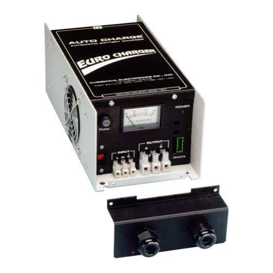
EURO CHARGER 1
INSTALLA TION GUIDE & MANUAL
MODEL #091-90-XX
NOTE : This charger is designed for vehicles with 3 batteries and negative ground.
INTRODUCTION
The Euro Charger, Model 091-90-xx is a compact, completely
automatic single channel battery charger designed specifically
for the fire service and emergency vehicles. Of rugged
construction, the charge is made to withstand the shock and
vibration encountered in vehicle mounted equipment. Utilizing
components which meet international safety requirements
makes this charger ideal for worldwide applications.
BATTERY CHARGER FEATURES
•
Completely automatic operation, charges battery on
demand
•
Input voltage, switch selectable, 115 volt or 230 volts
•
Output voltage regulated, eliminates overcharging battery
•
Output, current limited to protect charger from
overloading
•
Optional charge indicators
SPECIFICATION
CHARGE INDICATOR: 0-20 AMPS 5%
WEIGHT: 12 LBS
Model Number Input Voltage
091-90-12
115 / 230 Vac, 50/60 Hz
091-90-24
115 / 230 Vac, 50/60 Hz
Visit: www.evpeurope.com
Call: +44 (0) 1926 419441
E-mail: sales@evpeurope.com
EVP Ltd, Unit 4, Benford Court, Lower Cape, Warwick, CV34 5DA
TM
Input Current
Input Fuse
1.3 / 2.6 Amps
5 Amps
1.3 / 2.6 Amps
2.5 Amps
INSTALLATION
1.
The Euro Charger Automatic Battery Charger should be
installed in an area with adequate ventilation.
2. Mount the charger using the four holes provided.
3. Connect the wiring from the batteries to the output
terminal strip.
4. Double check battery wiring. Verify that battery voltage
appears at the charger output terminals.
5. Set the voltage selector to either the 115 volt or 230 volt
position to match the input source available.
6. Connect the input power to the input power terminal
strip and energize charger.
7.
Verify that power indicator is illuminated and charger is
charging.
WARRANTY
All products of Kussmaul Electronics Company Inc. are
warranted to be free of defects of material or workmanship.
Liability is limited to repairing or replacing at our factory,
without charge, any material or defects which become
apparent in normal use within 3 years from the date the
equipment was shipped. Equipment is to be returned, shipping
charges prepaid and will be returned, after repair, shipping
charges paid.
Kussmaul Electronics Company, Inc. shall have no liability for
damages of any kind to associated equipment arising from the
installation and /or use of the Kussmaul Electronics Company,
Inc. products. The purchaser, by the acceptance of the
equipment, assumes all liability for any damages which may
result from its installation, use or misuse, by the purchaser, his
or its employees or others.
Output Voltage Output Current
12
24
Output Fuse
12
25 Amps
6
12 Amps
Company Registration Number: 9121263
VAT number: 196484653
Advertisement

Related Manuals for KUSSMAUL EURO CHARGER 1


Summary of Contents for KUSSMAUL EURO CHARGER 1
- Page 1 SPECIFICATION Kussmaul Electronics Company, Inc. shall have no liability for damages of any kind to associated equipment arising from the CHARGE INDICATOR: 0-20 AMPS 5% installation and /or use of the Kussmaul Electronics Company, WEIGHT: 12 LBS Inc.
-
Page 2: Installation Wiring Diagram
INSTALLATION WIRING DIAGRAM EURO CHARGER 1, 091-90-XX INSTALLA TION GUIDE & MANUAL Optional Bar-Graph Indicator INSTALLATION WIRING DIAGRAM 091-94-XXE IMPORTANT: Charger output wire size is 14awg. Wire size is for a maximum length of 20 feet. If wiring is to be longer, larger wiring is required. - Page 3 INDICATOR INSTALLATION EURO CHARGER 1, 091-90-XX INSTALLA TION GUIDE & MANUAL INDICATOR INSTALLATION Locate indicator in a convenient place on the vehicle 5. Connect wiring to charger in accordance with the INDICATOR INSTALLATION 2. Place the template in position and center punch in 4...
-
Page 4: Dip Switch Settings
AUTO CHARGE 1000 PLC, 091-215-12 INSTALLA TION GUIDE & MANUAL DIP SWITCH SETTINGS DIP SWITCH SETTINGS SWITCH SHOWN IN OFF POSITION Legend on front panel of charger This is what the dip switch should look like when setting it to the legend on the front panel of the charger. - Page 5 Wiring Diagram shown is for a 10 foot installation AC Line Cord installed on back of unit 40 Amp fuse or Waterproof Circuit Breaker Kussmaul Part #: 090-0040-0 Install near the battery. AC Connections shall comply with UL recommendations, NEC, or NFPA...
- Page 6 AC Connections shall comply with UL recommendations, NEC, or NFPA standards 40 Amp fuse or Waterproof Circuit Breaker Kussmaul Part #: 090-0040-0 Install near the battery. CAUTION Connect wires to charger 2. Connect wires to battery 3. Apply AC power Accessories Battery Saver Loads (3 amps max.).
-
Page 7: Optional Accessories
Kussmaul Electronics Company, Inc. shall have no liability for damages of any kind to associated equipment arising from the installation and /or use of the Kussmaul Electronics Company, Inc. products. The purchaser, by the acceptance of the equipment, assumes all liability for any damages which may result from its installation, use or misuse, by the purchaser, his or its employees or others.