Table of Contents
Advertisement
Trouble Shooting Guide, Standard
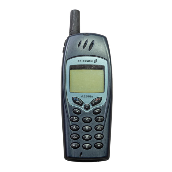
Applicable for A2618s and A2618sc
Contents
1
2
3
4
5
6
7
8
9
10
11
12
13
4/00021-2/FEA 209 544/25 A
Explanations ....................................................................................................................2
Network Problems...........................................................................................................5
On/Off Problems .............................................................................................................8
Audio Problems .............................................................................................................10
Display/Illumination Problems ....................................................................................13
Capacity/Charging Problems.......................................................................................17
SIM Problems................................................................................................................18
Key Problems.................................................................................................................20
Alert Problems...............................................................................................................21
Data Communication Problems...................................................................................22
Software Problems ........................................................................................................22
Other Problems .............................................................................................................23
Revision History ............................................................................................................24
Trouble Shooting Guide, Standard
Approved according to 1776-2/FEA 209 544
Advertisement
Table of Contents

Related Manuals for Ericsson A2618s


Summary of Contents for Ericsson A2618s
-
Page 1: Table Of Contents
Trouble Shooting Guide, Standard Trouble Shooting Guide, Standard Applicable for A2618s and A2618sc Contents Explanations ........................2 Network Problems......................5 On/Off Problems ......................8 Audio Problems ......................10 Display/Illumination Problems ..................13 Capacity/Charging Problems..................17 SIM Problems........................18 Key Problems.........................20 Alert Problems.......................21 Data Communication Problems...................22 Software Problems ......................22 Other Problems ......................23... -
Page 2: Explanations
Trouble Shooting Guide, Standard 1 Explanations Component Placement Reference For component placement see doc.1078-2/FEA 209 544/25 Service Test Menu Code to enter Service Test Menu, > * < < * < * External connectors External units are connected to the transceiver by means of an 11-pin connector on the bottom of the phone. - Page 3 Trouble Shooting Guide, Standard Abbreviations B: Crystal. C: Capacitor. D: Digital circuit. H: Buzzer, LED, and pads for display. J: Connector. L: Coil. N: Analogue circuit, power amplifier at some units. R: Resistor. S: Keyboard pads. V: Transistor, diode. X: Contact surface on the circuit board. Z: Filter.
- Page 4 Trouble Shooting Guide, Standard Pin placement Double diode or single Single diode (PIN diode) Electrolytic capacitor. transistor Five pin circuit (usually volt- Double transistor. N392 age regulator). Eight pin circuit. N200 N400 Crystal N300 4/00021-2/FEA 209 544/25 A 4(24)
-
Page 5: Network Problems
Trouble Shooting Guide, Standard 2 Network Problems Find out if the fault is RX- or TX-related Connect the unit (with signalling program) to a GSM test instrument and try to get SERV at an input signal strength of -68.5 dBm. If the unit does not get SERV, go to section 2.2. - Page 6 Trouble Shooting Guide, Standard If the VVCO-voltage is incorrect, measure the voltage at L700 3.7 ± 0.5 V measure on the pin close to R705. If the voltage on L700 is incorrect, on the pin close to R705, measure the resistance of L700 (0 Ohm).
- Page 7 Trouble Shooting Guide, Standard If you are not able to connect a call, open the unit and check for liquid damage. No action is to be taken for a liquid damaged unit, send the unit on according to the local company directives.
-
Page 8: On/Off Problems
Trouble Shooting Guide, Standard 3 On/Off Problems Make sure the battery connector is intact, clean and fully functional. Measure the resistance from VBATT to ground on X1:1. It should be more than 20 kohms. If it is less, usually only a few ohms there is probably a shortcut in N400. - Page 9 Trouble Shooting Guide, Standard Consumes less than 15 mA Open the unit and check for liquid damage. No action is to be taken for a liquid damaged unit, send the unit on according to the local company directives. Power up the board and start it by pressing On/Off key. Measure the VDIG-voltage on C723, measure on the side close to N700.
-
Page 10: Audio Problems
Trouble Shooting Guide, Standard 4 Audio Problems Connect a call from the unit that is to be tested, to a fully functional phone. Check that the microphone and the earphone of the unit works correctly. If the unit sounds strange (there is noise, distortion or the sound is “chopped”), send the unit on according to the local company directives. - Page 11 Trouble Shooting Guide, Standard Hands-free microphone out of order The fault appears when the audio path is interrupted somewhere between the hands-free microphone (connected through the system connector) and the input of N500. The audio path is shown in Fig. 4.1. Fig.
- Page 12 Trouble Shooting Guide, Standard Open the unit and check for liquid damage, especially around the system connector. No action is to be taken for a liquid damaged unit, send the unit on according to the local company directives. Make sure the system connector is not damaged or incorrectly soldered. Measure the resistance of C508 (>15 kohms).
-
Page 13: Display/Illumination Problems
Trouble Shooting Guide, Standard 5 Display/Illumination Problems Display Start the unit by pressing the On/Off key. If the unit does not start, go to chapter 3 (“On/Off Problems”). Use the Service Test menu. Choose “Display” and check the chess pattern. If the display is missing one or more of the segments, go to section 5.1.1. - Page 14 Trouble Shooting Guide, Standard Measure the voltage on R801 (VDIG 2.7 ± 0.10 V If the VDIG voltage is incorrect, go to chapter 2 (“On/Off Problems”). If the voltage is correct, measure the resistance of R801. (3,3 kohms). If the resistance is incorrect, replace R801. Measure the voltage on X850: 8, 2.7 ±...
- Page 15 Trouble Shooting Guide, Standard Illumination Use the Service Test menu. Choose LED/Illumination and check that the illumination lights. If the LCD-illumination does not lights, go to section 5.2.1. If the keyboard illumination does not lights, go to section 5.2.2. If the top indicator does not lights green, go to section 5.2.3. 5.2.1 LCD illumination glows faintly or does not glow at all Open the unit and check for liquid damage.
- Page 16 Trouble Shooting Guide, Standard If the KEY-led is not lit, measure the voltage on X850:3, 3.7 ± 0.50 V (VBATT) Fig .5.1. If the voltage on X850:3 is 0 V there is a foil damage, send the unit on according to the local company directives.
-
Page 17: Capacity/Charging Problems
Trouble Shooting Guide, Standard 6 Capacity/Charging Problems Make a visual check of the battery connector and the system connector. Replace them if needed. Insert a charged battery into the unit and start it up by pressing the On/Off key. Turn the unit on and connect a charger to the system connector to make sure if the fault remains. -
Page 18: Sim Problems
Trouble Shooting Guide, Standard 7 SIM Problems Definition of a SIM-problem Insert a functional SIM-card and a charged battery into the phone. If “Wrong card” or “Insert correct card” is displayed on the display when starting the phone it means that the phone is SIM-locked. NOTE! If the phone shall be SIM-locked, make sure that a correct SIM-card is used. - Page 19 Trouble Shooting Guide, Standard Measure the voltage at J800: 3, 2.5/1.5 ± 0.10 V . (SIMCONCLK). If the voltage is incorrect, measure the resistance of R806 (33 ohms). I f the resistance is incorrect, replace R806. If the voltage at J800: 3 still is incorrect, measure the resistance from pin 3 to pin 5 of J603 (>1 Mohm).
-
Page 20: Key Problems
Trouble Shooting Guide, Standard 8 Key Problems Start up the unit by pressing the On/Off key. If the unit does not start at all, go to chapter 3 (“On/Off Problems”). If the unit starts but none of the keys are functional, go to section 8.1. Use the Service Test menu and choose “Keyboard”. -
Page 21: Alert Problems
Trouble Shooting Guide, Standard 9 Alert Problems Start up the unit by pressing the On/Off key. If the unit does not start at all, go to chapter 3 (“On/Off Problems”). Use the Service Test menu and choose “Buzzer”. Activate the buzzer using the up/ down arrows. If there is no sound from the buzzer go to 9.1. -
Page 22: Data Communication Problems
Trouble Shooting Guide, Standard 10 Data Communication Problems Make a general visual inspection for corrosion or oxidation from liquid damage. No action is to be taken for a liquid damaged unit, send the unit on according to the local company directives. NOTE! All Fax and Data calls are initiated from the appropriate computer software. -
Page 23: Other Problems
Trouble Shooting Guide, Standard 12 Other Problems 12.1 Use the Service Test menu and choose “Real time clock”. Activate with YES. If it is not correct open the unit, make a general visual inspection for corrosion or oxidation from liquid damage. No action is to be taken for a liquid damaged unit, send the unit on according to the local company directives. -
Page 24: Revision History
Trouble Shooting Guide, Standard 13 Revision History Rev. Date Changes / Comments 2000-06-13 4/00021-2/FEA 209 544/25 A 24(24)