Table of Contents
Advertisement
Advertisement
Table of Contents
Troubleshooting

Related Manuals for Echo 77412


Summary of Contents for Echo 77412
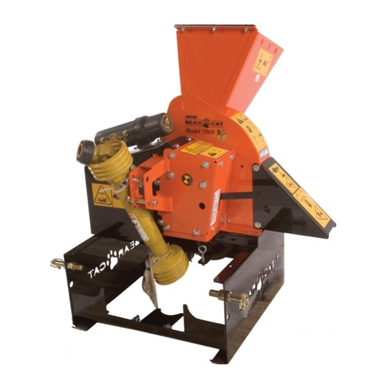
- Page 1 4.5 INCH CHIPPERS 77412 - 342CC BRIGGS ELECTRIC START 77413 - 390CC HONDA TOWABLE 77454 - 540 PTO 77412S - 342CC BRIGGS ELECTRIC START 77413S - 390CC HONDA TOWABLE 77454S - 540 PTO MADE WITH PRIDE IN THE... MADE WITH PRIDE IN THE...
- Page 2 Dear eCHo Bear Cat CusTomer Thank you for purchasing a ECHO Bear Cat product. The ECHO Bear Cat line is designed, tested, and manufactured to give years of dependable performance. To keep your machine operating at peak efficiency, it is necessary to adjust it correctly and make regular inspections.
- Page 3 limiTed WarranTY This warranty applies to all AG and Outdoor power Equipment manufactured by Crary Industries. Crary Industries warrants to the original owner each new Crary Industries product to be free from defects in material and workmanship, under normal use and service. The warranty shall extend 1 year from date of delivery for income producing (commercial) applications and 2 years from date of delivery for non-income producing (consumer) use of the product.
-
Page 4: Table Of Contents
Table of conTenTS deScriPTion Page SafeTY ..............................3 1.2 EmISSION INFORmATION 1.3 BEFORE OpERATING 1.4 OpERATION SAFETy 1.4 OpERATION SAFETy (CONT.) 1.5 pTO SAFETy 1.6 BATTERy SAFETy 1.7 mAINTENANCE/STORAGE SAFETy 1.8 TOWING SAFETy 1.9 SAFETy DECALS 1.9 SAFETy DECALS 1.10 SAFETy DECAL LOCATIONS 1.10 SAFETy DECAL LOCATIONS 1.10 SAFETy DECAL LOCATIONS aSSemblY ..............................11... -
Page 5: Safety
SafeTY Section 1.1 SafeTY alerT SYmbol 1.2 emiSSion informaTion Warning To all oWnerS in california and oTher STaTeS oPeraTing ouTdoor PoWer eQuiPmenT under California Law and under the laws of several other states, you are not permitted to operate an internal combustion engine using hydrocarbon fuels on any forest covered, brush covered or grass covered land or on land... -
Page 6: Before Operating
SAFETY 1.3 before oPeraTing keep all guards, deflectors, and shields in good working condition. Before inspecting or servicing any part of this machine, shut off power source, disconnect spark plug wire from spark plug and make sure all moving parts have come to a complete stop. -
Page 7: Operation Safety (Cont.)
SAFETY Before inspecting or ser- 1.4 oPeraTion SafeTY (conT.) vicing the pTO drive area, disengage the driveline, Shut off machine immediately if the machine becomes shut off power source, clogged, the cutting mechanism strikes any foreign remove key and make object, or the machine starts vibrating or making an sure all moving parts unusual noise. -
Page 8: Maintenance/Storage Safety
SAFETY 1.7 mainTenance/STorage SafeTY Before inspecting, servicing, storing, or changing an accessory, shut off power source, disconnect spark plug wire from spark plug and make sure all moving parts have come to a complete stop. Replace any missing or unreadable safety decals. Re- fer to the parts manual for part numbers when ordering safety decals from your chipper dealer. -
Page 9: Safety Decals
SAFETY 1.9 safeTy deCals 1.9 safeTy deCals See Section 1.10 for decal locations. Familiarize yourself with all of the safety and operating decals on the machine and the associated hazards. See the engine owners manual or contact the engine manufacturer for engine safety instructions and decals. -
Page 10: Safety Decal Locations
Refer to the parts catalog if you need a replacement decal. Decals that need replacement must be applied to their original locations. 1.10.1 modelS 77412, 77412S ("S" model ShoWn) *DECal 5, #12174, Is loCatED uNDERNEatH tHE bElt guaRD. -
Page 11: Safety Decal Locations
SAFETY 1.10 SafeTY decal locaTionS The numbers below correspond to the decals in Section 1.9. Familiarize yourself with all of the safety and operational decals on the machine and the associated hazards. See the engine owners manual or contact the engine manufacturer for engine safety instructions and decals. -
Page 12: Safety Decal Locations
SAFETY 1.10 SafeTY decal locaTionS The numbers below correspond to the decals in Section 1.9. Familiarize yourself with all of the safety and operational decals on the machine and the associated hazards. See the engine owners manual or contact the engine manufacturer for engine safety instructions and decals. -
Page 13: Assembly
Figure 1, standard trailer/hitch assembly (Models 77412, 77412s) The wheel base is adjustable from 36" to 46". Slide a wheel onto the axle and secure with a 5/8" washer and cotter pin. Repeat for the remaining wheel. -
Page 14: Trailer Assembly (390Cc Models)
ASSEMBLY optional configuration (figure 7): Locate the 2.2 Trailer assembly (390CC models) holes on the sides of the trailer closest to the engine. Align these holes with the top holes on the 2.2.1 lighTS axle support brackets located on the axle. Attach with one 3/8"... -
Page 15: Trailer Assembly (Cont.)
ASSEMBLY 2.2 Trailer aSSemblY (conT.) 2.3 diScharge aSSemblY 2.2.3 hiTch aSSemblY 2.3.1 diScharge caP Attach the hitch channel to the bottom of the trailer: move the chipper deflector weldment located inside the chipper housing to the down position (Figure 9). Standard configuration (figures 5 &... -
Page 16: Discharge Assembly (Cont.)
ASSEMBLY 2.3 diScharge aSSemblY (conT.) 2.5 chuTe eXTenSion 2.5.1 eXTenSion TraY (77412S, 77413S) Slide the discharge tube onto the chipper housing ensuring that the weldment bolts fit securely into the Attach the chipper chute flap and flap retainer to the notches on the disk cover (Figure 11). -
Page 17: Chute Extension (Cont.)
ASSEMBLY 2.7 checking fluidS (engine modelS) 2.5 chuTe eXTenSion (conT.) 2.5.1 chuTe eXTenSion (77454S) 2.7.1 checking/adding moTor oil Attach the chipper chute extension to the chipper chute Check the oil level. If needed, fill the engine with the type using six 3/8" x 1" carriage bolts, 3/8" washers and 3/8" and amount of oil specified in the engine owner's manual. -
Page 18: Checking Fluids (Cont.)
ASSEMBLY 2.7 checking fluidS (conT.) imPorTanT Do not attempt to start the engine at this time. Wait until you have read the complete starting instructions in the danger Operation Section of this manual. Gasoline is highly flammable and its vapors are explo- sive. -
Page 19: Controls & Operation
conTrolS & oPeraTion Section 3.1 engine model conTrolS 3.1.1 chiPPer conTrolS itch: On 390CC models, always use 2 inch (50 mm) ball and safety chains. Jack stand : Always have in up position and clear from ground when moving. When in use, place in DOWN position on a level surface. -
Page 20: Engine Model Controls (Cont.)
CONTROLS & OPERATION 3.1 engine model conTrolS (conT.) noTe For more detailed engine information, see the engine owners manual provided with the chipper. 3.1.2 engine conTrolS engine choke: use when starting a cold engine. push lever to ON position when starting. push to OFF posi- tion when engine is running. -
Page 21: Pto Model Controls
CONTROLS & OPERATION 3.2 PTo model conTrolS Three point hitch connection : mounts chipper to cauTion tractor three point hitch. PTo shaft : Connects chipper to tractor pTO shaft. Wear safety glasses at all times when operating the Avoid driveline angles over 20 degrees on pTO shaft machine. -
Page 22: Starting
CONTROLS & OPERATION 3.3 STarTing 3.3.2 STarTing recoil modelS cauTion move the machine to a clear, level area outdoors before move the machine to a clear, level area outdoors before starting. Do not operate in the vicinity of bystanders. make starting. -
Page 23: Stopping
CONTROLS & OPERATION Do not lean over the chipper chute to push objects 3.4 SToPPing into the cutting device. use a push stick or brush paddle. 3.4.1 SToPPing elecTric/recoil modelS Never use shovels or forks to feed brush. They can be chipped, are expensive to replace, and cause move the throttle to the SLOW position. -
Page 24: Attaching/Unhooking (Cont.)
CONTROLS & OPERATION 3.6 aTTaching/unhooking (conT.) Raise the jack stand and secure it to the hitch using a hitch pin. Connect the trailer wire harness to the towing vehicle. Test the trailer lights to ensure they are functioning properly. unhooking: unhook the safety chains (Figure 22) from the towing vehicle. -
Page 25: Service & Maintenance
Service & mainTenance Section 4.1 mainTenance Schedule The items listed in the service and maintenance schedule are to be checked, and if necessary, corrective action taken. This schedule is designed for units operating under normal conditions. If the unit is operating in adverse or severe usage conditions it may be necessary for the items to be checked and serviced more frequently. -
Page 26: Installing The Disk Lock
SERVICE & MAINTENANCE Warning BEFORE INSpECTING OR SERvICING ANy pART OF THIS mACHINE, SHuT OFF pOWER SOuRCE, DISCONNECT SpARk pLuG WIRE FROm SpARk pLuG AND mAkE SuRE ALL mOvING pARTS HAvE COmE TO A COmpLETE STOp. Severe vibration when feeding material into the chip- 4.2 inSTalling The diSk lock per. -
Page 27: Chipper Blades (Cont.)
SERVICE & MAINTENANCE Warning BEFORE INSpECTING OR SERvICING ANy pART OF THIS mACHINE, SHuT OFF pOWER SOuRCE, DISCONNECT SpARk pLuG WIRE FROm SpARk pLuG AND mAkE SuRE ALL mOvING pARTS HAvE COmE TO A COmpLETE STOp. 4.3 chiPPer bladeS (conT.) Warning 4.3.2 SharPening The bladeS It is important to ensure that the minimum gap between... -
Page 28: Drive Belt Adjustment
SERVICE & MAINTENANCE Warning BEFORE INSpECTING OR SERvICING ANy pART OF THIS mACHINE, SHuT OFF pOWER SOuRCE, DISCONNECT SpARk pLuG WIRE FROm SpARk pLuG AND mAkE SuRE ALL mOvING pARTS HAvE COmE TO A COmpLETE STOp. 4.4 drive belT adJuSTmenT Check the condition of the drive belt(s) annually or after If the bolts and nuts between the engine plate and the every 25 hours of operation, whichever comes first. -
Page 29: Drive Belt Replacement
SERVICE & MAINTENANCE Warning BEFORE INSpECTING OR SERvICING ANy pART OF THIS mACHINE, SHuT OFF pOWER SOuRCE, DISCONNECT SpARk pLuG WIRE FROm SpARk pLuG AND mAkE SuRE ALL mOvING pARTS HAvE COmE TO A COmpLETE STOp. 4.5 drive belT rePlacemenT 4.5.1 engine modelS bearing support weldment. -
Page 30: Drive Belt Replacement (Cont.)
Loosen the eye bolt to release tension on the belt position. (Figure 30). 7. For models 77412 and 77412S, the belt guide will Remove the 3/8" x 3-1/2" hex bolt, washer and nut have to be removed. To do this, remove the 1/2" bolt securing the idler pulley to the idler weldment. -
Page 31: Replacing Bearings (Cont.)
Replace the drive belt. using a straight edge, check the belt alignment. The two sheaves must be flush. For models 77412 and 77412S, reinstall the belt guide. With the engagement lever in the RELEASE position, reinstall the idler pulley. -
Page 32: Trailer Service Tips
SERVICE & MAINTENANCE Warning BEFORE INSpECTING OR SERvICING ANy pART OF THIS mACHINE, SHuT OFF pOWER SOuRCE, DISCONNECT SpARk pLuG WIRE FROm SpARk pLuG AND mAkE SuRE ALL mOvING pARTS HAvE COmE TO A COmpLETE STOp. The chipper models described in this manual have several 4.7 Trailer Service TiPS bearings and pivots that require greasing. -
Page 33: Greasing Bearings And Pivots (Cont.)
BEFORE INSpECTING OR SERvICING ANy pART OF THIS mACHINE, SHuT OFF pOWER SOuRCE, DISCONNECT SpARk pLuG WIRE FROm SpARk pLuG AND mAkE SuRE ALL mOvING pARTS HAvE COmE TO A COmpLETE STOp. 4.9 greasiNg beariNgs aNd PivoTs (CoNT.) 4.9.1 models 77412, 77412s, 77413, 77413s .18 oz 5 GRAMS .10 oz... -
Page 34: Greasing Bearings And Pivots (Cont.)
SERVICE & MAINTENANCE Warning BEFORE INSpECTING OR SERvICING ANy pART OF THIS mACHINE, SHuT OFF pOWER SOuRCE, DISCONNECT SpARk pLuG WIRE FROm SpARk pLuG AND mAkE SuRE ALL mOvING pARTS HAvE COmE TO A COmpLETE STOp. 4.9 greasiNg beariNgs aNd PivoTs (CoNT.) 4.9.2 models 77454, 77454s INSIDE SHIELD INSIDE SHIELD... -
Page 35: Troubleshooting
TroubleShooTing Section 5.1 general TroubleShooTing Before performing any of the corrections in this troubleshooting chart, refer to the appropriate information contained in this manual for the correct safety precautions and operating or maintenance procedures. Contact your nearest dealer or the factory for service problems with the machine. Problem PoSSible cauSe remedY... -
Page 36: General Troubleshooting
TROUBLESHOOTING 5.1 general TroubleShooTing Problem PoSSible cauSe remedY Drive belt too loose or broken. Replace belt or spring. Rotor will not turn. Obstructed discharge. Use branch or similar object to clear discharge. plugged rotor. Clear rotor. Feed material more evenly. Improper belt installation;... -
Page 37: Size Specifications
SPecificaTionS Section 6.1 Size SPecificaTionS SPecificaTionS (77412, 77412S) SPecificaTionS (77413, 77413S) 68" x 43" x 41-1/2" (77412) 76" x 43.5" x 46" (77413) OvERALL SIzE OvERALL SIzE 68" x 57" x 53" (77412S) 76" x 57.5" x 58" (77413S) mAx. CHIppER mAx. -
Page 38: Bolt Torque
SPECIFICATIONS 6.2 bolT TorQue The tables below are for reference purposes only and their use by anyone is entirely voluntary, unless otherwise noted. Reliance on their content for any purpose is at the sole risk of that person and any loss or damage resulting from the use of this information is the responsibility of that person. - Page 39 237 NW 12 Street P.O. Box 849 West Fargo, ND 58078-0849 Declares that hereunder specified unit: CHIPPER Brand: ECHO Bear Cat Type: Engine driven Chipper Model Number: 77413 Complies with the requirements of: Machinery Directive 2006/42/EC EN 13525:2005-Forestry Machinery-Wood Chippers-Safety...
- Page 40 237 NW 12 Street P.O. Box 849 West Fargo, ND 58078-0849 Declares that hereunder specified unit: CHIPPER Brand: ECHO Type: Engine driven Chipper Model Number: 77412E Complies with the requirements of: Machinery Directive 2006/42/EC EN 13525:2005-Forestry Machinery-Wood Chippers-Safety Emission of Gaseous and Particulate Pollutants Directive 2002/88/EC...
- Page 41 -Conformity Assessment Procedure: Annex V (Use of harmonized standard EN ISO 3744:2010) Sound Power Level: 87 dB L Guaranteed Sound Power Level: 107 dB L 77412 Serial number 401131 thru 709864 West Fargo, ND 58078-0849 June 29, 2011 CRARY INDUSTRIES, INC.
- Page 42 237 NW 12 Street P.O. Box 849 West Fargo, ND 58078-0849 Declares that hereunder specified unit: CHIPPER Brand: ECHO Bear Cat Type: PTO driven Chipper Model Number: 77454 Complies with the requirements of: Machinery Directive 2006/42/EC EN 13525:2005-Forestry Machinery-Wood Chippers-Safety...
- Page 43 crary industries 237 NW 12th Street, West Fargo, ND 58078-0849 Phone: 701.282.5520 • Toll free: 800.247.7335 fax: 701.282.9522 e-mail: service@bearcatproducts.com • sales@bearcatproducts.com www.bearcatproducts.com...