Advertisement
Quick Links
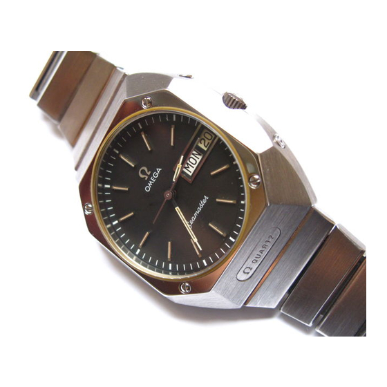
Technical guide
C
ALIBRE
1310
29 Q SCS CALD CORR CORH CORS STS 8 jewels
Folder 1 - Replacement of power cell
o 29.00 mm
/
6.35 mm
Movement height
Jewel number
8
Frequency
32'768 A/h
IMPORTANT
To be observed strictly
The watch must in no case be demagnetized.
In order not to disturb the proper functioning of
the watch the electronic module (fig. 1.1) must not
be touched with the fingers.
The new power cell should be manipulated by
means of tweezers with insulated tips (fig. 2.1).
EQUIPMENT
Electronic module fig 1.1
Insulated tweezers.
fig 2.1
English
1
Cal. 1310
1973
Advertisement

Related Manuals for Omega 1310


Summary of Contents for Omega 1310
- Page 1 (fig. 1.1) must not be touched with the fingers. The new power cell should be manipulated by means of tweezers with insulated tips (fig. 2.1). EQUIPMENT Electronic module fig 1.1 Insulated tweezers. fig 2.1 English Cal. 1310 1973...
- Page 2 1.1. Open the case. 1.2. Remove and clean the back. 1.3. Remove magnetic protection. 1.4. Remove power cell bridle No. 1310.9179 by unscrewing its screw. 1.5. Remove by suction any possible metal waste caused by the screw of the power cell bridle.
- Page 3 In order not to disturb the proper functioning of the watch, the electronic module (fig. 1.2) must not be touched either with a tool - except key for trimmer - or with the fingers. EQUIPMENT Key for trimmer DELTATEST Electronic module fig. 1.2 English Cal. 1310 1973...
- Page 4 If the daily rate is higher than the possible correction limits, the electronic module should Generally, a measuring time of 10 seconds and be replaced (see folder 3-1310). a measuring accuracy of 1/100th second will be used. 2.4. Read instant rate shown on DELTATEST.
- Page 5 4.2, in order to compensate the loss caused by closing of the case. 2.6. Grease the water-resistance gasket. Close the case. 2.7. Set the watch and check frequency on DELTATEST after 24 hours. fig. 4.2 Cal. 1310 1973...
- Page 6 Do not clean the electronic module and motor module in bath:. EQUIPMENT Movement holder 1310. Key for trimmer 1301. Tool for adjusting motor eccentric. Deltatest measuring apparatus. Alitest checking apparatus. Feed by substitute power cell 1310. Microscope. English Cal. 1310 1973...
- Page 7 If this is not so, take off 3.3. Remove hand-setting stem No. the second hand and move it by 1 second 1310.9030 by pressing the head of the before refitting. setting lever staff (red plastic) No.
- Page 8 (6a). 3.27. Remove the second hand. 3.28. Unscrew the wheel train bridge screw No. 2377 (7) and withdraw the wheel train bridge No. 1310.9001. 3.29. Remove second wheel No. 1310.9010 and third wheel No. 1310.9014. Fig. 2.3 Cal. 1310 1973...
- Page 9 Unscrew the 2 motor connecting screws (2), motor module screw No. 2377 (8) and motor eccentric locking screw No. 2582 (9). 3.31. Extract faulty motor module No. 1310.9200. 3.32. Place new motor module in position. 3.33. Important : Screw very slightly the 2 motor connecting screws (2) and motor module screw (8).
- Page 10 (12). The tip of the blade must be at the top of a tooth, as close as possible, without touching it (position a, fig. 5.3.). If necessary, move retaining click plate No. 1310.9026 (13) by turning the eccentric of click bearing plate No. 1310.9029 (14).
- Page 11 Do not clean the electronic module and motor module in baths. EQUIPMENT Movement holder 1310. Key for trimmer 1301. Tool for adjusting motor eccentric. Deltatest measuring apparatus. Alitest checking apparatus. Feed by substitute power cell 1310. Microscope. English Cal. 1310 1973...
- Page 12 Cal. 1310 1973...
- Page 13 Cal. 1310 1973...
- Page 14 Cal. 1310 1973...
-
Page 15: Cleaning Instructions
Power cell 9903. Upper magnetic protection 1310.9230. The remainder of the movement, including the motor eccentric 1310.9227 left on the plate (only remove it in case of replacement) may be cleaned in baths as per the usual procedure. Cal. 1310... - Page 16 Cal. 1310 1973...
- Page 17 Cal. 1310 1973...
- Page 18 Cal. 1310 1973...
- Page 19 Nos. 1310.9062 and 1310.9064. Check on positioning : make the day disc driving gear No. 1310. 9057 turn slightly until the three fingers are visible; one of the three magnetic teeth must then be located under the upper pinion of the day disc driving gear No.
- Page 20 Indications in brackets [ ] refer to the Deltatest ODT 1 and Alitest OAT 1. All apparatus which do not bear the model number on the back plate correspond with the ODT 1 and OAT 1. English Cal. 1310 1973...
- Page 21 (5)). Note The motor is said to function normally when the second wheel makes one complete revolution in one minute. It is important to check the passage of each of the 60 teeth. Cal. 1310 1973...
- Page 22 Following up requests by our General Agents, we are presenting a refined check-method to make servicing of caliber 1310 easier. The contents of the technical guide, folder 0 to 6, remain valid. 1. CHECK DELTATEST Accepted rate : + 0.10 at + 0.30 s./d.
- Page 23 (Limit for motor only 3 µA) operations 3.36 to 3.38 of the technical guide 3-1310 and check thereafter the following procedure . 5. FUNCTIONING LIMITS (WHOLE WATCH) Lower limit : 1.20 V upper limit : 1.40 V...
- Page 24 The first movement of the wheel must be considered and not the movement caused by addition of the endshake of the rotor. Cal. 1310 1973...