
Related Manuals for Lenovo ThinkSystem HR350A


Summary of Contents for Lenovo ThinkSystem HR350A
- Page 1 ThinkSystem HR350A User Guide and Hardware Maintenance Manual Please read this manual before using the product.
-
Page 2: Table Of Contents
Contents Disclaimer ................................8 Trademarks ................................9 Safety Information ............................... 10 Chapter 1 Introduction ............................15 1.1 Product overview ............................15 1.2 Features ..............................15 1.2.1 High reliability ............................ 15 1.2.2 High availability ..........................15 1.2.3 High expandability ..........................15 1.2.4 High manageability .......................... - Page 3 2.2.15 M.2 drive replacement........................35 2.2.16 System board replacement ........................ 35 Chapter 3. BIOS Setup ............................38 3.1 Introduction ..............................38 3.2 POST Screen .............................. 38 3.3 Main ................................40 3.3.1 BIOS Information ..........................40 3.3.2 System Language ..........................40 3.3.3 System Date/Time ..........................
- Page 4 3.9.6 BMC User Settings ..........................90 Chapter 4. BMC Setup ............................94 4.1 Overview of the Lenovo Think System Management Module ..............94 4.2 Configuration of the ThinkSystem Remote Management Module ............95 4.3 ThinkSystem Remote Management Module Quick Start................96 4.3.1 Prestart..............................
- Page 5 4.9 Configuration ............................106 4.9.1 Active Directory ..........................106 4.9.2 DNS ..............................106 4.9.3 Event Log ............................107 4.9.4 Images Redirection ..........................107 4.9.5 LDAP/E-Directory Settings ......................108 4.9.6 Mouse Mode............................108 4.9.7 Network ............................. 109 4.9.8 Network Link ............................ 109 4.9.9 NTP ..............................
- Page 6 5.2.4 Replacing the system board battery ....................126 Appendix A CentOS 7.5 Installation Guide ....................... 127 1. Introduction ..............................127 1.1 System Requirements ........................... 127 2. Installing CentOS ............................128 2.1 Installing CentOS via Installation Media ..................... 128 2.2 Installing CentOS via PXE ........................132 3.
- Page 7 2.17 Set Fault LED Mask ........................... 155 2.18 Get Fault LED Mask .......................... 156 2.19 Set Fan Speed ............................. 157 2.20 Get System Error Status ........................158 2.21 Get ID LED Status ..........................158 2.22 Get Riser Mode ..........................159 2.23 Get SEP Status Register ........................
-
Page 8: Disclaimer
Alternatively, you may contact the seller for more information. Lenovo shall not be liable for any damage that may result from the improper installation, use or storage of this Product in proper manner or as instructed in this manual, or of any damage that may result from the repair or modification of this Product by anyone other than authorized technical personnel. -
Page 9: Trademarks
Trademarks LENOVO, and THINKSYSTEM are trademarks of Lenovo. eMAG is a trademark of the Ampere Corporation in the United States or other countries. Linux is a registered trademark of Linus Torvalds. All other trademarks are the property of their respective owners. © 2019 Lenovo. -
Page 10: Safety Information
Safety Information IMPORTANT: Each caution and danger statement in this document is labeled with a number. This number is used to cross reference an English-language caution or danger statement with translated versions of the caution or danger statement in the Safety Information document. - Page 11 Statement 3 CAUTION: When laser products (such as CD-ROMs, DVD drives, fiber optic devices, or transmitters) are installed, note the following: •Do not remove the covers. Removing the covers of laser products may result in exposure to hazardous laser radiation. There are no serviceable parts inside these devices.
- Page 12 Statement 7 CAUTION: If the device has doors, ensure that you remove or secure the doors before moving or lifting the device to protect against personal injury. The doors will not support the weight of the device. Statement 8 CAUTION: Never remove the cover on a power supply or any part that has the following label attached. Hazardous voltage, current, and energy levels are present inside any component that has this label attached.
- Page 13 Statement 14 CAUTION: Some accessory or option board outputs exceed Class 2 or limited power source limits. You must install the appropriate interconnecting cabling in accordance with your local electrical code requirements. Statement 15 CAUTION: The power-control button on the device may put the device in standby mode instead of turning off the device. In addition, the device may have multiple connections to DC power.
- Page 14 Statement 19 CAUTION: Hazardous moving parts are nearby. Keep fingers and other body parts away. Statement 20 The device is equipped with a replaceable battery. Using an incorrect battery may present a risk of explosion. Caution: Risk of explosion if battery is replaced with an incorrect type. Dispose of used batteries as instructed. Statement 21 This device is not intended for use in the direct field of view at visual display workplaces.
-
Page 15: Chapter 1 Introduction
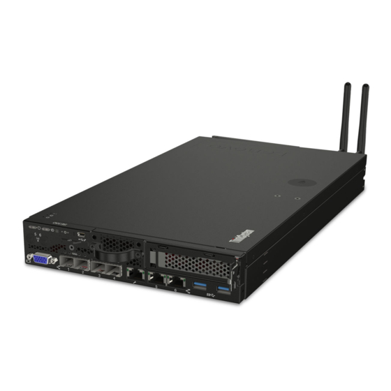
Chapter 1 Introduction This chapter provides an overview of the server and details its features and specifications. Depending on the model, some features might not be available, or some specifications might not apply. 1.1 Product overview The ThinkSystem™ HR350A is a 2U rack server that combines performance, flexibility, and manageability into a package. It uses the latest Ampere ARM eMAG 8180 server processor and supports up to 16 DDR4 dual-inline memory modules (DIMMs). -
Page 16: Specifications
CentOS 7.5, Oracle Linux 7.5 Operating system Note: The supported operating system varies with system configurations. If you have any question, contact Lenovo. Supported altitude* (unpressurized): 0-10 000 ft (0-3048 m) Altitude A2: Operating temperature value decreases by 1° C (1.8° F) with every 300 m (984 ft) of altitude increase. - Page 17 Minimum: 200 V ac Maximum: 240 V ac Power Two 550-watt hot-swap power supplies for redundancy support Height: 86.5 mm (3.4 inches) Width: With rack latches: 482.0 mm (19.0 inches) Without rack latches: 434.4 mm (17.1 inches) Dimensions Depth: With rack latches: 763.7 mm (30.1 inches) Without rack latches: 750.0 mm (29.5.
-
Page 18: Chapter 2 Server Components And Hardware Replacement Procedures
Note: The following procedures should only be performed by qualified operators or service personnel trained in server maintenance. Do not perform any removal procedure until you have read and understood all warnings and cautions stated in the "Lenovo Server User Guide - Read Me First" (hereinafter referred to as "Read Me First"). All removals should be performed strictly as instructed. -
Page 19: Server Components
2.1 Server components 2.1.1 Front view Figure 1 Front view of the server (eight 2.5-inch HDD configuration) 1. 2.5-inch hot-swap drive (optional) 2. Rack handle (left) 3. Front controller module 4. Rack handle (right) 5. Front VGA Connector 2.1.2 Rear view Figure 2 Rear views of the server 1. -
Page 20: Front Control Panel
2.1.3 Front control panel Figure 3 Front control panel 1. Steady green light: the server is on. 1. Power button with power status LED 2. Off: the server is off. 3. Blinking green: the server is DC off. 1. Steady blue light: the server is identified. 2. -
Page 21: Server Components
2.1.4 Server components 1. M.2 Clip 2. System Board Handle 3. Riser Slot 1 4. M.2 Connector (PCIe) 5. TPM Connector 6. RTC Battery 7. Front USB Connector 8. Front VGA Connector 9. Front Panel Connector 10. System Board Handle 11. -
Page 22: Hardware Replacement Procedures
2.2 Hardware replacement procedures Safety Precautions Read and follow all safety precautions specified in "Read Me First". If the instructions provided with the server differs from the instructions contained in this manual, contact a service technician from the supplier to confirm the correct procedures. Note: The power button does not completely turn off the AC current supplied to the device. -
Page 23: Parts List
2.2.1 Parts list 1. System Main Board 2. Power Supply 3. Riser 2 Bracket 4. Riser 1 Bracket 5. Chassis Base 6. HDD Module 7. Eight 2.5 HDD Backplanes 8. System Fan Cage 9. 6038 Fan Module 10. System Air-duct... -
Page 24: Rack Handles Replacement
2.2.2 Rack handles replacement Do not proceed before reading and understanding the "Safety Precautions" section of this chapter and "Read Me First". CAUTION: Do not place any object on top of rack-mounted products. The power-control button on the device may put the device in standby mode instead of turning off the device. In addition, the device may have multiple connections to DC power. -
Page 25: Air Duct Replacement
To reinstall, reverse the steps above 2.2.4 Air duct replacement Do not proceed before reading and understanding the "Safety Precautions" section of this chapter and "Read Me First". CAUTION: If your server has air ducts or air baffles, do not remove them while the server is running. Operating the server without the air ducts or air baffles might cause the microprocessor(s) to overheat. -
Page 26: Backplane Replacement
Removing the system air duct To reinstall, reverse the steps above. 2.2.5 Backplane replacement Do not proceed before reading and understanding the "Safety Precautions" section of this chapter and "Read Me First". CAUTION: The power-control button on the device may put the device in standby mode instead of turning off the device. In addition, the device may have multiple connections to DC power. -
Page 27: Memory Module Replacement
To reinstall, reverse the steps above. 2.2.6 Memory module replacement Do not proceed before reading and understanding the "Safety Precautions" section of this chapter and "Read Me First". CAUTION: The following label indicates a sharp-edge hazard. To install a memory module, do the following: 1. -
Page 28: Riser Module Replacement
Installing a memory module. To remove, reverse the steps above. 2.2.7 Riser module replacement Do not proceed before reading and understanding the "Safety Precautions" section of this chapter and "Read Me First". To remove the riser 1 and riser 2 rear HDD module assembly, do the following: 1. - Page 29 4. Remove the riser assembly. See "2.2.7 Riser module replacement". 5. Press the tab (Step1) to pivot the card latch to the open position (Step 2) on the PCIe cage module. 6. Pull the PCIe card outwards to remove it. (Step 3). Removing PCIe card To remove a riser card, do the following: 1.
-
Page 30: Cpu Heat Sink Replacement
Installation slots for PCIe cards 2.2.9 CPU heat sink replacement Do not proceed before reading and understanding the "Safety Precautions" section of this chapter and "Read Me First". CAUTION: The heat sink might be very hot. Turn off the server and wait several minutes to let the server cool before removing the server cover. -
Page 31: Hot-Swap Drive Dummy Tray Replacement
2.2.10 Hot-swap drive dummy tray replacement Do not proceed before reading and understanding the "Safety Precautions" section of this chapter and "Read Me First". Note: The diagrams below are relevant for servers with 2.5-inch hard drive configuration only. To remove the dummy tray for a 2.5-inch hot-swap drive, do the following: Grab the handle of the dummy tray. -
Page 32: Hot-Swap Drive Replacement
2.2.11 Hot-swap drive replacement Do not proceed before reading and understanding the "Safety Precautions" section of this chapter and "Read Me First". Note: The diagrams below are only for servers with 2.5-inch hard drive configuration. To remove a 2.5-inch hot-swap drive, do the following: 1. -
Page 33: Hot-Swap Power Supply Replacement
2.2.12 Hot-swap power supply replacement Do not proceed before reading and understanding the "Safety Precautions" section of this chapter and "Read Me First". CAUTION: Hazardous moving parts. Keep fingers and other body parts away. CAUTION: Disconnect the hot-swap fan cables before removing the fan from the device to protect against personal injury. -
Page 34: System Fan Replacement
2.2.13 System fan replacement Do not proceed before reading and understanding the "Safety Precautions" section of this chapter and "Read Me First". Caution: Hazardous moving parts. Keep fingers and other body parts away. To remove a system fan, do the following: 1. -
Page 35: Drive Replacement
2.2.15 M.2 drive replacement Do not proceed before reading and understanding the "Safety Precautions" section of this chapter and "Read Me First". 1. Turn off all attached devices and the server. 2. Disconnect the ac power cord from the electrical outlet. 3. - Page 36 To install 1. Handle the system board by grabbing the plunger & handle (position 1, 2). 2. Align to location pin (Position 3) on chassis and put down the system board. 3. Slide to the rear of the chassis.
-
Page 38: Chapter 3. Bios Setup
Chapter 3. BIOS Setup 3.1 Introduction This chapter describes the functions and features provided by eMAG™ UEFI for the HR 350A. 3.2 POST Screen The POST screen is the first page displayed when the system starts up. There are two kinds of POST screens: ... - Page 39 Quiet POST screen: the screen which contains only the Lenovo logo. By default, quiet POST screen is enabled. Users can switch to normal POST screen by pressing ESC. Below information should be displayed in POST screen: BIOS and firmware version ...
-
Page 40: Main
3.3 Main 3.3.1 BIOS Information Below BIOS Information is shown in the Main setup screen: 1. Product Name 2. Core Version 3. Compliancy 4. BIOS Build ID 5. BIOS Version 6. Build Date and Time 7. Access Level 3.3.2 System Language Allows user to change the language displayed. -
Page 41: Platform Board Information
3.3.4 Platform Board Information Display general information about the board, including board name, SCP firmware version, clock, and so on. -
Page 42: Functional Jumper Status
3.3.5 Functional Jumper Status This screen shows status of the functional jumpers and the corresponding IPMI commands. Jumper: ‘Open’ if the jumper is not set. Otherwise ‘Close’. IPMI bit: ‘Unset’ if users have not executed the IPMI command to set the corresponding function. Otherwise, ‘Set’. -
Page 43: Advanced
3.4 Advanced Use the arrow keys to select Advanced on top of the screen. The Advanced Configuration screen looks like below. If the system is unstable after changing any settings in advanced configuration, revert to the default settings in the “Save & Exit” screen. Use the arrow keys to select each screen and press Enter to access the submenu items. -
Page 44: Acpi Settings
3.4.1 ACPI Settings ACPI Settings Description Select Enabled to let the BIOS select the best ACPI options for the system. Enable ACPI Auto Configuration Select Disabled to manual change ACPI following settings. ACPI Sleep State Supports only Sleep State S3. The options are S3 and Disabled. -
Page 45: Smart Settings
Enable Turbo mode Allow the system to go to Turbo mode in which the system may run at highest speed 3.3 GHz. This mode can be changed only when the Chip supports it. If the Chip does not support Turbo mode, this configuration will be hidden. The options are Enabled and Disabled. -
Page 46: X86 Emulator Configuration
3.4.3 X86 Emulator Configuration This screen allows users to enable X86 Emulator support. The options are Enabled and Disabled. 3.4.4 APEI Configuration APEI Enable: Allow the system to support APEI (ACPI Platform Error Interface). Enable this feature to make the system report any HW errors to OS. -
Page 47: General Watchdog Timer
3.4.5 General Watchdog Timer OS Watchdog Timeout: This feature allows the system reboot when OS fail to boot. Use this feature if your OS fully support ARM general Watchdog Timer. Select Disabled if not sure. The options are Enabled and Disabled. -
Page 48: Serial Port Console Redirection
3.4.6 Serial Port Console Redirection This setup screen allows users to configure serial ports for COM0 and Out-of-Band Management port. More detailed information is in below sections. - Page 49 3.4.6.1 COM0 Console Redirection: Select Enabled to enable console redirection support for a serial port specified by the user. The options are Enabled and Disabled. If the item above set to Enabled, the following items will become available for user’s configuration: Console ReDirection Settings Description Terminal Type...
- Page 50 - Select Space to add a Space as a parity Bit to Be sent with your data Bits. The options are None, Even, Odd, Mark, and Space. Stop Bits A stop bit indicates the end of a serial data packet. Select 1 Stop Bit for standard serial data communication.
- Page 51 3.4.6.2 Serial Port for Out-of-Band Management/Windows Emergency Management Services (EMS) Console Redirection: Select Enabled to enable SOL console redirection support for a serial port specified by the user. The options are Enabled and Disabled.
-
Page 52: Pci Subsystem Settings
If the item above set to Enabled, the following items will become available for user’s configuration: Console Redirection Settings Description Terminal Type This feature allows the user to select the target terminal emulation type for Console Redirection. Select VT100 to use the ASCII Character set. Select VT100+ to add color and function key support. - Page 53 Below table explains about PCIE Device Common setting, applied for all devices: PCIE Device Common Settings Description Above 4G DecoDing This setting Enables or Disables 64-bit capable devices ability to be decoded in above 4G address space. SR-IOV Support If the system has SR-IOV capable PCI-E devices, the setting will Enable or Disable the Single Root IO Virtualization Support for the system.
- Page 54 PCI Express Link Register Settings ASPM Support Set the ASPM Level: - Force L0s - Force all links to L0s State - AUTO - BIOS auto configure - DISABLE - DisaBles ASPM Extended Synch If Enabled, allows generation of Extended Synchronization patterns. Link Training Retry Defines number of Retry Attempts software will take to retrain the link if previous training attempt was unsuccessful.
- Page 55 3.4.7.2. PCI Express GEN 2 Settings...
- Page 56 Setting Description PCI Express GEN2 Device Register Settings Completion Timeout In device Functions that support Completion Timeout programmability, allows system software to modify the Completion Timeout value. ‘Default’ 50us to. 50ms. If ‘Shorter’ is selected, software will use shorter timeout ranges supported by hardware. If ‘Longer’ is selected, software will use longer timeout ranges.
-
Page 57: Network Stack Configuration
If supported by hardware and set to ‘Disabled’, this will disable the hardware’s ability to Hardware Autonomous Speed change link speed except speed rate reduction for the purpose of correcting unstable link operation. The default setting is ‘Enabled’. 3.4.8 Network Stack Configuration Setting Description Network Stack... -
Page 58: Nvme Configuration
Medhand-ia Detect count Number of times the presence of media will be checked. Use either +/- or numeric keys to set the value. The default value: 1 3.4.9 NVMe Configuration This screen displays information about the NVMe devices detected in the system. When user selects a device name, more detail information will be displayed as below figures: When user selects a device name, more detailed information will be displayed as seen below:... -
Page 60: Sata Configuration
3.4.10 SATA Configuration This screen displays information about SATA devices detected in the system. SATA Controller (S:X B: X D:X F:X): Displays the SATA info of the SATA controller on a PCIe downstream device. -
Page 61: Usb Configuration
3.4.11 USB Configuration This screen displays the detected USB devices installed on the system. Below table explains fields from this USB configuration setting: Setting Description USB Controllers Number of USB controllers installed in the system. USB Devices Displays list of category USB devices detected in the system. XHCI HanD-off This is a workaround for OSes without XHCI hand-off support. - Page 63 3.4.12 iSCSI Configuration This feature allows the user to enter the unique name of the iSCSI Initiator in IQN format.
- Page 64 3.4.13 Driver Health From the Advance tab, press Enter at the “Driver Health” to enter this setup screen. This screen shows all the PCI devices that their driver installs the driver health protocol. Enter the selected item to know the status of the driver like healthy, failed, configuration (Depends on the information that the driver provides).
-
Page 65: Other Configuration Items
3.4.14 Other Configuration Items Depend on the device drivers for the PCIE devices plugged, additional menu items might be displayed on the Advance setup page. - Page 66 Entering this menu item will allow users to configure the device parameters:...
-
Page 67: Chipset
3.5 Chipset Use the arrow keys to select Chipset on top of the screen. The Chipset Configuration screen looks like below. This screen allows you to change settings such as turn on/off some Chip’s IPs. If the system is unstable after changing any settings in advanced configuration, revert to the default settings in the “Save & Exit” screen. -
Page 68: Ahci Controller Configuration
3.5.1 AHCI Controller Configuration AHCI Controller 0: This option allows to enable/disable AHCI controller 0 which controls SATA port 0/1. AHCI Controller 1: This option allows to enable/disable AHCI controller 1 which controls SATA port 2/3. -
Page 69: Cpu Configuration
3.5.2 CPU Configuration L3 Cache Size: Display the size of CPU L3 Cache in MB. Number of cores enabled: Display the number of cores enabled in this system. Number of cores configuration: Input the number of cores to be enabled in the system. This option requires a system reboot to take effect. -
Page 70: Memory Configuration
3.5.3 Memory Configuration Memory Configuration parameters are explained in the following table: Setting Description Total memory The total memory installed in the system. Effective Memory The memory that can be used for BIOS and OSes. Some memory is preserved for Firmware which is not available to use. - Page 71 Patrol Scrub: Enable/disable Patrol Scrub for DDR controller.
-
Page 72: Ethernet Controller Configuration
3.5.4 Ethernet Controller Configuration This setting allows users to enable/disable the LOM Controller. Note that there is no LOM controller available in the M/B board so users should never enable this option. -
Page 73: Vga Controller Configuration
3.5.5 VGA Controller Configuration Allow users to enable/disable the Aspeed VGA controller. When disabled is selected, the on-board VGA controller will not be available to use. -
Page 74: Xhci Controller Configuration
3.5.6 XHCI Controller Configuration Port 0: allows to enable/disable the USB port 0. Port 1: allows to enable/disable the USB port 1. -
Page 75: Pcie Controller Configuration
3.5.7 PCIE Controller Configuration NOTE: PCIe configuration is auto-configured by the BIOS based on the detected riser cards. Users should never change anything in this menu. -
Page 76: Security Configuration
3.6 Security Configuration Use the arrow keys to select Security on top of the screen. The Security Configuration screen looks like below: Administrator Password: allows users to set Administrator password. User Password: allows users to set User password. The Administrator and User Password MUST follow below policy: - String length 8~20 characters;... -
Page 77: Secure Boot
3.6.1 Secure Boot Allow users to configure boot mode and key management. Secure Boot: Allow users to enable/disable secure boot feature. The default value is ‘Disabled’. Secure Boot feature is active if Secure Boot is Enabled, Platform Key (PK) is enrolled and the system is in User Mode. The mode change requires a platform reset. - Page 78 3.6.1.1 Key Management Key management access the following format: Public Key Certificate: EFI Signature List, EFI CERT X509 (DER Encoded), EFI CERT RSA2048 (Bin), EFI SERT SHAXXX Authenticated UEFI Variable Key Source: Factory, External, Mixed. Setting for key management: ...
-
Page 79: Boot
4. Forbidden Signatures: This feature allows the user to configure the settings of the Forbidden Signatures. User can update/append it using value from Factory Defaults or from a file in the file system. 5. Authorized TimeStamps: This feature allows the user to configure the settings of the Authorized TimeStamps. User can update/append it using value from Factory Defaults or from a file in the file system. -
Page 80: Save & Exit
3.8 Save & Exit Use the arrow keys to select Save & Exit on top of the screen. The Save and Exit screen looks like below. 3.8.1 Save Options Save Changes and Exit: Set this option to exit system setup after saving the changes. ... -
Page 81: Boot Override
3.8.3 Boot Override Listed in this section are all the boot options for the system. Select an option and press Enter. The system will boot to the selected boot option. 3.9 Server Management Use the arrow keys to select Server mgmt on top of the screen. The Server mgmt screen looks like below. ... - Page 82 View System Event Log: This feature allows you to view all the System Event Log entries. It may take time to retrieve all logs. BMC User Settings: Press Enter to go to the BMC User Setting setup page. More information is in section 3, 9, and 6. ...
-
Page 83: System Event Logs
3.9.1 System Event Logs SEL Components: Change this to enable or disable event logging for error/progress codes during boot. The default value is Eanbled. Erase SEL: Select Yes, on next reset to erase all system event logs upon next system reboot. Select No to keep all system event logs after each system reboot. -
Page 84: Bmc Self-Test Log
3.9.2 BMC self-test log Erase Log: The option to erase log on every reset or keep it. The default value is ‘Yes, on every reset’. When log is full: Select the action to be taken when log is full. The options are: ‘Clear log’, ‘Do not log any more’. -
Page 85: View Fru Information
3.9.3 View FRU Information... -
Page 86: Bmc Network Configuration
3.9.4 BMC Network Configuration 3.9.4.1 Configure IPv4 support Configuration Address source: This feature allows the user to select the source of the IP address for the BMC network. If Static is selected, you will need to know the BMC IP and enter it into the system manually. If DynamicBmcDhcp is selected, the BMC IP will be requested using DHCP from the management controller. - Page 87 3.4.9.2 Configure IPv6 support Configuration Address source: This feature allows the user to select the source of the IP address for the BMC network. If Static is selected, you will need to know the BMC IP and enter it into the system manually. If DynamicBmcDhcp is selected the BMC IP will be requested using DHCP from the management controller.
-
Page 88: View System Event Log
3.9.5 View System Event Log This feature allows to view all the System Event Log. It may take time to retrieve all logs. -
Page 90: Bmc User Settings
3.9.6 BMC User Settings This section allows users to Add/Delete and Set Privilege levels for BMC users. - Page 91 Add User Add a user to the BMC user list. To add a user, you need to fill out the following information: User Name: press Enter to fill in the user name you would like to create. User Password: press Enter to fill in the user password (and confirm the password). ...
- Page 92 Del User Delete a user from BMC’s user list. To delete a user, you need to fill out the following information. If the information matches, the user will be deleted. The information includes: User Name: press Enter to fill the user name. ...
- Page 93 Change User Settings Change user settings. To change the settings of a user, you need to fill out the user name and password before other settings can be changed. The settings that can be changed are: User: Enable/disable the access for this user. If Disabled is selected, then this user doesn’t have access to BMC. ...
-
Page 94: Chapter 4. Bmc Setup
Chapter 4. BMC Setup 4.1 Overview of the Lenovo Think System Management Module This section describes the features of the Remote Management Module. The Remote Management Module runs on the server system as an integrated solution and integrates the embedded operating system. -
Page 95: Configuration Of The Thinksystem Remote Management Module
4.2 Configuration of the ThinkSystem Remote Management Module When first installed, the Remote Management Module by default will search DHCP server on the network to automatically assign IP address, subnet mask and gateway. It is recommended that users manually set a fixed IP address in the BIOS. To set an IP address, do the following: 1. -
Page 96: Thinksystem Remote Management Module Quick Start
For more information about the initial settings, see Chapter 3 “Configuration of the ThinkSystem Remote Management Module” on page XXX. The user name in this topic is “lenovo”. Besides “lenovo”, other user names and passwords are also accepted. The default user name and password are as follows: •... - Page 97 Figure 2. Configuring IE ESC - step 2 Figure 3. Configuring IE ESC - step 3...
-
Page 98: Log-On
For making the remote console (KVM) window of the managed server works, you must install Java runtime environment (JRE) V6.0 Update 24 or later. 4.3.2 Log-on To log on to the ThinkSystem Remote Management Module, do the following: 1. Enter the IP address assigned by the ThinkSystem Remote Management Module into the Web browser. For example: http://10.223.131.36/ For secure connection, refer to the following example:... -
Page 99: Navigation
4.3.3 Navigation When the ThinkSystem Remote Management Module is successfully logged on, the ThinkSystem Remote Management Module home page is displayed. There are several tabs on the vertical toolbar which is on the left pane of the ThinkSystem Remote Management Module home page. By clicking these tabs, you can get the specific system information and take the relevant tasks listed in the following table: Table 2. -
Page 100: Log-Out
This group of pages allows you to do the following. The menu contains the following items: • Firmware Update Firmware Update • Protocol Configuration • Dual Image Configuration Maintenance BMC configuration and firmware. • Preserve Configuration • Restore Configuration Maintenance •... -
Page 101: Thinksystem Remote Management Module Web Console Options
4.4 ThinkSystem Remote Management Module Web Console Options This topic describes every page of the Web console and each page is divided into several parts corresponding separately to the several tabs at the left side of the panel. In each part, there are detailed illustrations and introductions for each menu option. 4.4.1 Dashboard By default, the home page of the ThinkSystem Remote Management Module shows the Dashboard page, including general information about the server. -
Page 102: Sensor
4.5 Sensor 4.5.1 Sensor Reading A list of sensor readings will be displayed here. Click on a record to show more information about that particular sensor, including thresholds and a graphical representation of all associated events. 4.6 System Inventory 4.6.1 CPU This page gives detailed information for the CPU present in this system. -
Page 103: Dimm
4.6.2 DIMM This page gives detailed information for the DIMM present in this system. 4.7 FRU Information 4.7.1 Field Replaceable Unit (FRU) Information This page displays the BMC FRU file information. On selecting any particular FRU Device ID its corresponding FRU information will be displayed. -
Page 104: Ipmi Event Log
4.8.1 IPMI Event Log This page displays the list of events incurred by different sensors on this device. Click on a record to see the details of that entry. Also use the sensor type or sensor name filter options to view those specific events logged in the device. -
Page 105: System Log
4.8.2 System Log This page displays logs of system events for this device. 4.8.3 Audit Log This page displays logs of audit events for this device. -
Page 106: Configuration
4.9 Configuration 4.9.1 Active Directory An active directory is a directory structure used on Microsoft Windows based computers and servers to store information and data about networks and domains. 4.9.2 DNS The Domain Name System (DNS) is a distributed hierarchical naming system for computers, services, or any resource connected to the Internet or a private network. -
Page 107: Event Log
4.9.3 Event Log 4.9.4 Images Redirection This page is used to configure the images into BMC for redirection. -
Page 108: Ldap/E-Directory Settings
4.9.5 LDAP/E-Directory Settings The Lightweight Directory Access Protocol (LDAP)/E-Directory Settings is an application protocol for querying and modifying data of directory services implemented in Internet Protocol (IP) networks. 4.9.6 Mouse Mode This page is used to configure the media into BMC for redirection. -
Page 109: Network
4.9.7 Network This page is used to configure the network settings for the available LAN channels. 4.9.8 Network Link This field is used to configure the video recording function of the KVM server and SOL setting. -
Page 110: Ntp
4.9.9 NTP The Network Time Protocol (NTP) is a protocol for synchronizing the clocks of computer systems over packet-switched, variable-latency data networks. It is designed particularly to resist the effects of variable latency by using a jitter buffer. 4.9.10 PAM Order Settings This page is used to configure the PAM order for user authentication into the BMC. -
Page 111: Platform Event Filter
4.9.11 Platform Event Filter This platform event filter provides a mechanism for configuring the BMC to take selected actions on event messages that it receives or has internally generated. 4.9.12 RADIUS Radius is a modular, high performance and feature-rich RADIUS suite including server, clients, development libraries and numerous additional Radius related utilities. -
Page 112: Services
4.9.13 Services This page list all services running on the BMC, click icon on the right side of service to view and modify the service configuration. 4.9.14 SMTP Settings This page is used to configure the SMTP settings. -
Page 113: Ssl Settings
4.9.15 SSL Settings This field is used to configure SSL certificate into the BMC. 4.9.16 System and Audit Log In MegaRAC GUI, System and Audit log page displays a list of system logs and audit logs occurred in this device. -
Page 114: System Firewall
4.9.17 System Firewall This field is used to configure firewall setting. 4.9.18 User Management This page is used to manage users. By clicking user icon, administrator can add a new user and modify or delete the existing users. -
Page 115: Virtual Media
4.9.19 Virtual Media 4.9.20 IPMI Configuration 4.10 Remote Control This page is used to launch KVM. -
Page 116: Maintenance
4.11 Maintenance 4.11.1 Preserve Configuration This page allows you to select the specific configuration items to be backup. 4.11.2 Restore Configuration This page allows user to restore the configuration files from the client system to the BMC. - Page 117 Select the option you want to save, or Select "Select All" to save All configurations, and click "save". Click "Backup Configration" to download the Backup configuration file...
- Page 118 Select "Restore Configuration" and upload the downloaded backup files.
-
Page 119: System Administrator
4.11.3 System Administrator This page is used to configure the System Administrator settings. 4.11.4 Backup and Restore Configuration This page allows you to configure BMC Recovery settings. -
Page 121: Firmware Update
4.11.5 Firmware Update This wizard takes you through the process of firmware upgradation. Click “Enter Update Mode” - Select the BMC firmware to update - select Upload. - Check on Full Flash checkbox to flash all then click on Proceed to start firmware update. - Page 122 The upgrade process will start. After upgrade complete, BMC will automatically restart. Out-of-bound WebUI update Below steps can be done to upgrade SCP and BIOS firmware using WebUI: - Login to WebUI - Select Firmware Update à Firmware Update - Select HPM option then click Continue.
- Page 123 Select OK to continue.
- Page 124 Click on the “Choose File” button, browser and choose the SCP image to upgrade - Click OK to continue Select “Update All” checkbox and click on “Process” button to continue. Click OK to confirm the action. After the upgrade complete, reload the page to continue to use WebUI.
-
Page 125: Chapter 5. Troubleshooting And Diagnostics
Chapter 5. Troubleshooting and diagnostics 5.1 Problems with initial start up Should you encounter any problem starting up the system for the first time, follow the suggested actions below, in the listed order, until the problem is resolved: 1. Verify that the server's hardware configuration is as stated on the packing list. 2. -
Page 126: Replacing The System Board Battery
Contact your local Lenovo service center to have the above procedures performed at your site. Note: All maintenance work performed by the user shall be at his/her own risk. Lenovo shall not be responsible for any hardware damage that may arise as a consequence. -
Page 127: Appendix A Centos 7.5 Installation Guide
Appendix A CentOS 7.5 Installation Guide 1. Introduction This document provides the instructions for installing and working with CentOS on eMAG server platforms. At the time of this writing, CentOS 7.5 with Linux kernel 4.14 is supported. 1.1 System Requirements •... -
Page 128: Installing Centos
2. Installing CentOS 2.1 Installing CentOS via Installation Media 2.1.1 Preparing CentOS Installation Media Prepare one USB storage device (8GB) and one SATA drive. On a Linux machine, download the latest CentOS ISO file and dd to a USB storage device (>= 8GB) $ wget http://mirror.centos.org/altarch/7/isos/aarch64/CentOS-7-aarch64-Everything-1804.iso $ dd if= CentOS-7-aarch64-Everything-1804.iso of=/dev/sdX $ sync... - Page 129 In the UEFI Shell, after typing FS0:\EFI\BOOT\BOOTAA64.EFI, the following menu will be displayed: Install CentOS Linux AltArch 7 Test this media & install CentOS Linux AltArch 7 Troubleshooting --> Use the ↑ and ↓ keys to change the selection. Press 'e' to edit the selected item, or 'c' for a command prompt. Move the cursor to Install CentOS Linux AltArch 7.
- Page 130 Press “b” to start installation. Wait for the installation to complete, and then hit “Return” to reboot. Performing post-installation setup tasks Configuring installed system Writing network configuration Creating users Configuring addons Generating initramfs Running post-installation scripts Installation complete. Press return to quit After system reboot, BIOS will select CentOS as the first boot entry.
- Page 131 2.1.3.2 Updating Ampere Computing Generic CentOS Kernel Obtain the Ampere Computing CentOS tarball. It should have a name similar to amp_sw_centos_7.5-yymmdd.tar.xz. # tar xvf amp_sw_centos_7.5-yymmdd.tar.xz # cd aarch64/ # ls kernel-headers-4.14.0-49.el7.yymmdd+amp.aarch64.rpm kernel-4.14.0-49.el7.yymmdd+amp.aarch64.rpm kernel-devel-4.14.0-49.el7.yymmdd+amp.aarch64.rpm kernel-debug-4.14.0-49.el7.yymmdd+amp.aarch64.rpm kernel-debug-devel-4.14.0-49.el7.yymmdd+amp.aarch64.rpm # yum –y install *.rpm # reboot WARNING: If the vanilla kernel is newer than the Ampere Computing CentOS kernel mentioned in the README, the update may fail.
-
Page 132: Installing Centos Via Pxe
2.2 Installing CentOS via PXE 2.2.1 Preparing PXE Installation System System Configuration Figure 1: A Server running Ubuntu (15.04 or later) or CentOS 7.x Configuring PXE Server Installing necessary packages: • Ubuntu 15.x: # apt-get install -y isc-dhcp-server xinetd tftpd-hpa wget apache2 •... - Page 133 class "pxeclients" { match if substring (option vendor-class-identifier, 0, 9) = "PXEClient"; if option arch = 00:0b { # Installing Centos filename "/AMP/centos-repo/EFI/BOOT/grubaa64.efi"; # systemctl enable dhcpd # systemctl restart dhcpd Downloading the CentOS 7 ISO file and creating PXE repository. # wget http://mirror.centos.org/altarch/7/isos/aarch64/CentOS-7-aarch64-Everything.iso # mkdir -p /media/centos-arm64-iso/ # mount -o loop CentOS-7-aarch64-Everything.iso /media/centos-arm64-iso...
- Page 134 insmod gzio insmod part_gpt insmod ext2 set timeout=60 ### END /etc/grub.d/00_header ### search --no-floppy --set=root -l 'CentOS-7-AArch64' ### BEGIN /etc/grub.d/10_linux ### menuentry 'Install CentOS Linux 7' --class red --class gnu-linux --class gnu --class os { linux /AMP/centos-repo/images/pxeboot/vmlinuz inst.stage2=http://172.168.1.23/AMP/centos-repo ro initrd /AMP/centos-repo/images/pxeboot/initrd.img menuentry 'Test this media &...
- Page 135 $ sudo systemctl stop firewalld $ sudo systemctl disable firewalld • CentOS 7.x: # vi /etc/xinetd.d/tftp service tftp socket_type = dgram protocol = udp wait = yes user = root server = /usr/sbin/in.tftpd server_args = -c -s /var/lib/tftpboot disable = no per_source = 11 = 100 2...
- Page 136 2.2.2 Installing CentOS 2.2.2.1 Instructions for Aptio Setup Utility Boot the system to Aptio Setup Utility by pressing “Esc” during system boot-up. Select the “Save & Exit” tab and then select Ethernet PXE boot entry, as shown below. Aptio Setup Utility - Copyright (C) 2017 American Megatrends, Inc. Main Advanced Security...
-
Page 137: Activating Management Ethernet
3. Activating Management Ethernet If the network configuration is skipped during the installation, try the following to activate eth0 as the Management Ethernet. Make sure the board’s Ethernet is connected to the network. Edit the CentOS network script as in the example below. # vi /etc/sysconfig/network-scripts/ifcfg-eth0 TYPE=Ethernet BOOTPROTO=dhcp... -
Page 138: Gnome Desktop Support (Optional)
4. GNOME Desktop Support (Optional) If GUI is not selected during installation, follow the steps below for support: Install additional xorg-x11-server packages. # yum groups install “GNOME Desktop” # yum install xorg-x11-server-devel # yum install libXrandr-devel Start X server with GNOME. # startx Enable GUI as default system target. -
Page 139: Building Centos Kernel
5. Building CentOS Kernel 5.1 Setting up Native CentOS Development Environment First, install the necessary development packages (if not done already). # yum groupinstall "Development Tools" # yum install ncurses-devel # yum install hmaccalc zlib-devel binutils-devel elfutils-devel libelf-devel newt-devel python-devel # yum install audit-libs-devel numactl-devel pciutils-devel openssl-devel # yum install bc bison perl-ExtUtils-Embed.noarch xmlto asciidoc 5.2 Building Ampere Computing CentOS Kernel... - Page 140 Extract kernel source package: $ tar xf amp_sw_centos_7.5-yymmdd.src.tar.xz Install the SRPM. $ cd SRPMS/ $ rpm –ivh kernel-aarch64-4.14.0-49.el7.yymmdd+amp.src.rpm Build the kernel source. $ cd ~/rpmbuild $ ls SOURCES/ SPECS/ $ rpmbuild --define "%_topdir `pwd`" –bb --without debuginfo --without perf --without tools SPECS/kernel-xgene.spec # To build ILP32 kernel, use the ilp32-src package and kernel-xgene-optimized.spec $ rpmbuild --define "%_topdir `pwd`"...
-
Page 141: Ampere Computing Centos Ras/Apei Support
6. Ampere Computing CentOS RAS/APEI Support The Ampere Computing CentOS kernel is compiled with ACPI Platform Error Interface (APEI) support and Generic Hardware Error Source (GHES) support. GHES is a non-x86 specific error type in APEI for describing error sources via the Hardware Error Source (HEST) table. It is a defined mechanism for reporting errors to the kernel from firmware CONFIG_ACPI_APEI=y CONFIG_ACPI_APEI_GHES=y... -
Page 142: Centos Ahci Platform Boot Failure Recovery
7. CentOS AHCI Platform Boot Failure Recovery In BIOS version 4.05 series, the SATA driver was switched from Ampere Computing eMAG driver to standard AHCI platform driver. This creates a disk detection issue at boot time if you originally installed CentOS with Ampere Computing eMAG SATA driver. To recover from this boot failure, follow the steps below: Boot up CentOS using rescue kernel. -
Page 143: Kvm Support
8. KVM Support Mismatching of the Linux kernel, QEMU and libVirt could cause errors when using virtual machines. The user must take care to update all packages to the latest within a target release. Mixing packages from different releases could result in unpredictable behavior. Therefore, to set up VM, it is recommended to use one of the following options: •... -
Page 144: Appendix B Hr350A Oem Command Specification
Appendix B HR350A OEM Command Specification 1. Introduction This document describes detail OEM commands that are specific for the HR350A board. -
Page 145: Hr350A Oem Commands
2. HR350A OEM Commands 2.1 Load UEFI default setting The command is used to erase the UEFI NVRAM, command will be affected on next boot. Linux command: $ ipmitool raw 0x3c 0x1 Description: NetFn 0x3c Command Request data: Response data: Byte Data field Completion Code... -
Page 146: Set Or Un-Set The Uefi Manufacturing Mode (Deprecated)
2.3 Set or un-set the UEFI manufacturing mode (Deprecated) The command is used to set the UEFI to run on manufacturing mode on next boot. Linux command: $ ipmitool raw 0x3c 0x2 0x4 0xff Description: NetFn 0x3c Command Request data: 0x4 –... -
Page 147: Hide Or Un-Hide The Uefi Menu
2.4 Hide or un-hide the UEFI menu The command is used for UEFI to Hide / Un-hide the UEFI menu setting. Linux command: $ ipmitool raw 0x3c 0x2 0x8 0xff Description: NetFn 0x3c Command Request data: Mask 0x8 – Use bit 3 to control the feature, the effect depends on the value. [7:0] 0x0 - Trigger to disable the feature that running at manufacturing mode 0xff - Trigger to enable the Value... -
Page 148: Mux Switching Command
Request data: Response data: Completion Completion Code UEFI Flag [7:4] - Reserve [3] 1b = Hide/Un-hide UEFI setting [2] 1b = Set/Un-set UEFI manufacturing mode (Deprecated) [1] 1b = Clear/Un-clear UEFI password [0] 1b = Reserved 2.6 MUX Switching command The command is used to switch the MUX lines to SOL and SYS. -
Page 149: Get Mux Configuration
Response data: Byte Data field Completion Code Direction: 00 – MUX to SYS 01 – MUX to BMC 02 – MUX to SOL 2.7 Get MUX Configuration The command is used to get the MUX configuration for the specify port. Linux command: $ ipmitool raw 0x3c 0xe0 <Port Index>... -
Page 150: Write Bmc Mac Address To Fru
Description: 0x32 – The AMI NetFn NetFn Command 0x66 Request Data: Response Data: Byte Data field Completion Code 2.9 Write BMC MAC Address to FRU This is the AMI command that support to write BMC MAC address to FRU. Linux command: $ ipmitool raw 0x3c 0x4 0x0 0xB0 0xB1 0xB2 0xB3 0xB4 0xB5 $ ipmitool raw 0x3c 0x4 0x1 0xB0 0xB1 0xB2 0xB3 0xB4 0xB6 Description:... -
Page 151: Notify Bmc Backup Component (Deprecated)
2.10 Notify BMC backup component (Deprecated) This is the command to notify BMC uses the recent component as backup component. Linux command: $ ipmitool raw 0x3c 0x09 0x04 (Backup BIOS Component) $ ipmitool raw 0x3c 0x09 0x20 (Backup BOOTFW Component) $ ipmitool raw 0x3c 0x09 0x24 (Backup BOTH Component) Description: NetFn... -
Page 152: Clean Backup Component
NetFn 0x3c Command 0x08 Request Data: Byte Data field Component ID (BIOS: 04h, BOOTW: 20h, BOTH: 24h) [7:6] – Reserved [5] – BOOTFW Component (SCP) [4:3] – Reserved [2] – BIOS Component [1:0] – Reserved Response Data: Byte Data field Completion Code Requested Component ID Result:... -
Page 153: Disable Cooling Manager Support
Component ID (BIOS: 04h, BOOTW: 20h, BOTH: 24h) [7:6] – Reserved [5] – BOOTFW Component (SCP) [4:3] – Reserved [2] – BIOS Component [1:0] – Reserved Response Data: Byte Data field Completion Code Requested Component ID Result: 00h: Success 20h: Failed to clean BOOTFW – No BOOTFW Image Found 04h: Failed to clean BIOS –... -
Page 154: Get Cooling Manager Status
Result: 01h: Disabled 00h: Enabled 2.14 Get cooling manager status This is the command to get cooling manager support status. Linux command: $ ipmitool raw 0x3c 0x0c Description: NetFn 0x3c Command 0x0c Request Data: Byte Data field NONE NONE Response Data: Byte Data field Completion Code... -
Page 155: Get Fault Led Status
Status 01h – Turn on fault led 00h – Turn off fault led (Fault led mask will be automatically set to 0x00 to mask all of errors, user needs to use command 0x12 to set mask to 0xff again so that fault led will works as normal, see detail in command “Set Fault Led Mask”) Response Data: Byte... -
Page 156: Get Fault Led Mask
NetFn 0x3c 0x12 Command Request Data: Byte Data field Mask Byte 0xFF: Any of below errors will turn on fault led 0x00: Mask all of errors The bit description is below: [7] – PSU Error Mask [6] – Undetermined Error Mask [5] –... -
Page 157: Set Fan Speed
Byte Data field Completion Code Mask [7] – PSU Error Mask [6] – Undetermined Error Mask [5] – CPU Fault Mask [4] – Overtemp Mask [3] – Hightemp Mask [2] – DIMM Error Mask [1] – FAN Error Mask [0] – Sensor Error Mask 2.19 Set Fan Speed This is the command to set fan pwm duty cycle. -
Page 158: Get System Error Status
2.20 Get System Error Status This is the command to get system error status. Linux command: $ ipmitool raw 0x3c 0x15 Description: NetFn 0x3c 0x15 Command Request Data: Byte Data field NONE NONE Response Data: Byte Data field Completion Code System Error Status [7] –... -
Page 159: Get Riser Mode
NONE NONE Response Data: Byte Data field Completion Code Status 01h: LED is currently on 00h: LED is currently off 2.22 Get Riser Mode This is the command to get riser mode. Linux command: $ ipmitool raw 0x3c 0x17 Description: NetFn 0x3c 0x17... -
Page 160: Get Chassis Type
$ ipmitool raw 0x3c 0x18 Description: NetFn 0x3c Command 0x18 Request Data: Byte Data field PSOC NUM 0x00: PSOC 0 (SEP4S/2U or SEP4M/1U) 0x01: PSOC 1 (SEP4M/2U) Response Data: Byte Data field Completion Code 2:12 SEP Status Register (See detail in Item #8.2: SEP Status Register, BP Spec Rev 1.08) 2.24 Get Chassis Type This command is to get system chassis type (1U/2U). -
Page 161: Enable/Disable Socflash Support
Chassis Type 0: 1U chassis 1: 2U chassis 2.25 Enable/Disable SOCFlash Support This command is to enable/disable socflash support. This command only works with LAN channel and privilege access permission. Linux command: $ ipmitool -I lanplus -H <BMCIP> -U <USERNAME> -P <PASSWORD> raw 0x3c 0x20 Description: NetFn 0x3c... -
Page 162: Trigger Sol Archive
Response Data: Byte Data field Completion Code Enable/Disable Status: 1: Enabled 0: Disabled 2.27 Trigger SOL Archive This command is to trigger SOL archive log so that user can download it via ipmitool/webui. Linux command: $ ipmitool raw 0x3c 0x22 Description: NetFn 0x3c... -
Page 163: Write Psu Registers
Request Data: Data field Byte PSU Number 1: PSU1 2: PSU2 PSU Command Code (See PSU Spec for detail) Response Data: Byte Data field Completion Code PSU Register Value (See PSU Spec for detail) 2.29 Write PSU Registers This command is to write PSU registers. Linux command: $ ipmitool raw 0x3c 0x24 Description:... -
Page 164: Enable/Disable Auto-Recovery Support
2.30 Enable/Disable Auto-recovery Support This command is to enable/disable auto-recovery support. Linux command: $ ipmitool raw 0x3c 0x26 Description: NetFn 0x3c Command 0x26 Request Data: Byte Data field 1: Enable 0: Disable Component ID 2: BIOS Component 5: SCP Component Response Data: Byte Data field... -
Page 165: Get Component Firmware Version
Component ID 2: BIOS Component 5: SCP Component Response Data: Data field Byte Completion Code Current Enable/Disable Status 1: Enabled 0: Disabled 2.32 Get Component Firmware Version This command is to get component firmware version. Linux command: $ ipmitool raw 0x3c 0x28 Description: NetFn 0x3c... -
Page 166: Sync Rtc Time (Utc) To Bmc
Description: NetFn 0x3c 0x29 Command Request Data: Byte Data field NONE NONE Response Data: Byte Data field Completion Code 2.34 Sync RTC Time (UTC) to BMC This command is to sync rtc time (utc) to bmc. Linux command: $ ipmitool raw 0x3c 0x30 Description: 0x3c NetFn... - Page 167 Description: NetFn 0x3c Command 0x33 Request Data: Byte Data field PSOC NUM 0x00: PSOC 0 (SEP4S/2U or SEP4M/1U) 0x01: PSOC 1 (SEP4M/2U) Response Data: Byte Data field Completion Code SEP Control Register (See BP Spec for detail)
-
Page 168: Standard Ipmi Command
3. Standard IPMI command 1.1 Lock / Unlock the power button This is standard IPMI command which used to control to lock or unlock the power button. Linux command: $ ipmitool raw 0x0 0xa 0x1 Description: 0x0 – The standard chassis NetFn NetFn 0xa –... -
Page 169: Appendix C- Terms And Abbreviations
Appendix C- Terms and Abbreviations BIOS Basic Input/Output System Bits per second. CMOS Complementary Metal Oxide Semiconductor COM serial port MS-DOS supports up to four serial ports. The default interrupt for COM1 and COM3 is IRQ4; the default interrupt for COM2 and COM 4 is IRQ3. - Page 170 Internet Protocol Interrupt Request; A signal sent to the microprocessor via an IRQ line to inform the later of impending data sending or receipt by peripheral devices. Kilobytes, equivalent to 1024 bytes. Local Area Network Liquid Crystal Display Light Emitting Diode; An electronic device that emits light when a current passes through it. Logical Unit Number Megabytes;...
- Page 171 Self-Monitoring Analysis and Reporting Technology SNMP Simple Network Management Protocol TCP/IP Transmission Control Protocol/Internet Protocol Uninterrupted Power Supply Universal Serial Bus...