Table of Contents
Advertisement
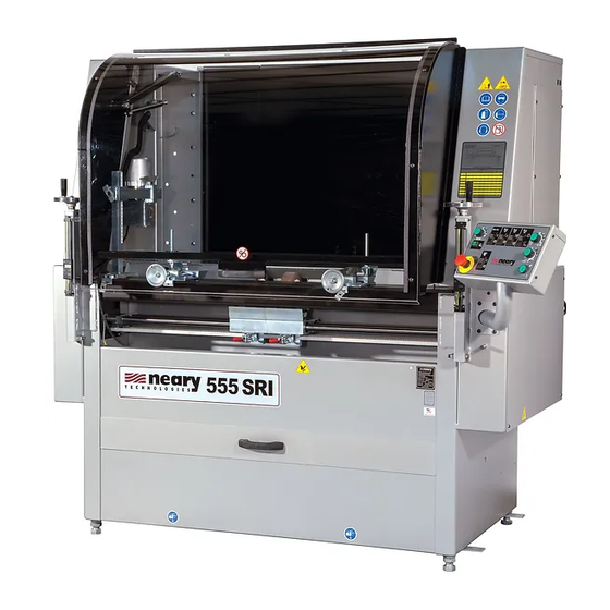
REEL MOWER GRINDER
6,010,394 & 6,290,581
6,685,544 & 6,699,103
You must thoroughly read and understand all manuals before operating the equipment,
paying particular attention to the Warning & Safety instructions.
555
AUTO - INDEX
SPIN / RELIEF
Patent No. 5,321,912
SERVICE
MANUAL
- ORIGINAL INSTRUCTIONS -
55013 (3-17)
Advertisement
Table of Contents
Troubleshooting

Related Manuals for Neary 555 SRI

Summary of Contents for Neary 555 SRI
- Page 1 - ORIGINAL INSTRUCTIONS - AUTO - INDEX SPIN / RELIEF REEL MOWER GRINDER Patent No. 5,321,912 6,010,394 & 6,290,581 6,685,544 & 6,699,103 SERVICE MANUAL You must thoroughly read and understand all manuals before operating the equipment, paying particular attention to the Warning & Safety instructions. 55013 (3-17)
- Page 2 - ORIGINAL INSTRUCTIONS - IMPORTANT SAFETY MESSAGE As manufacturers of sharpening equipment, we want to confirm to you, our customers, our concern for safety. We also want to remind you about the simple, basic, and common sense rules of safety when using this equipment.
- Page 3 - ORIGINAL INSTRUCTIONS - TABLE OF CONTENTS Safety Message ......................2 Safety Instructions ....................3 -6 Service Data and Adjustments ................. 7 -21 Trouble Shooting ...................... 22 -39 Parts Diagram ......................40 - 71 Wiring Diagram ......................72 - 73 Wiring Schematic......................
- Page 4 SAFETY INSTRUCTIONS - ORIGINAL INSTRUCTIONS - TO AVOID INJURY, READ AND UNDERSTAND THE SAFETY ITEMS LISTED BELOW. IF YOU DO NOT UNDERSTAND ANY PART OF THIS MANUAL AND NEED ASSISTANCE, CONTACT YOUR LOCAL DEALER. 1. KEEP GUARDS IN PLACE and in working order. 13.
- Page 5 SAFETY INSTRUCTIONS - ORIGINAL INSTRUCTIONS - IMPROPER USE OF GRINDING WHEEL MAY CAUSE BREAKAGE AND SERIOUS INJURY. GRINDING IS A SAFE OPERATION IF THE FEW BASIC RULES LISTED BELOW ARE FOLLOWED. THESE RULES ARE BASED ON MATERIAL CONTAINED IN THE ANSI B7.1 SAFETY CODE FOR "USE, CARE AND PROTECTION OF ABRASIVE WHEELS".
- Page 6 SAFETY INSTRUCTIONS - ORIGINAL INSTRUCTIONS - UNPLUG THE EQUIPMENT PRIOR TO DOING ANY SERVICE ON THIS EQUIPMENT. FAILURE TO REMOVE POWER TO THIS EQUIPMENT BEFORE SERVICING MAY RESULT IN INJURY OR DEATH. IF POWER IS REQUIRED FOR TESTING OR TROUBLESHOOTING, THIS SHOULD BE PERFORMED BY A TRAINED PROFESSIONAL OR LICENSED ELECTRICIAN.
- Page 7 SERVICE DATA - ORIGINAL INSTRUCTIONS - SKILL AND TRAINING REQUIRED FOR SERVICING This Service Manual is designed for technicians who have the necessary mechanical and electrical knowledge and skills to reliably test and repair the 555 Spin/Relief Grinder. For those without the background, service can be arranged through your local distributor.
- Page 8 PERIODIC MAINTENANCE - ORIGINAL INSTRUCTIONS - DAILY MAINTENANCE IS SPECIFIED ON PAGE 7 OF THE OPERATOR'S MANUAL AND IS TO BE PERFORMED BY THE OPERATOR. LISTED BELOW ARE PERIODIC MAINTENANCE ITEMS TO BE PERFORMED BY YOUR COMPANY'S MAINTENANCE DEPARTMENT: 1. Clean the dust tray located at the lower front of the machine monthly using a vacuum or by removing it.
- Page 9 LUBRICATION - ORIGINAL INSTRUCTIONS - LUBRICATION OF GRINDING SHAFT AND LINEAR BEARINGS STEP 1 – Thoroughly clean all three shafts. STEP 2 – Flood spray all three shafts with CRC 3-36 until the lubricant is dripping off the shafts. Do not use a teflon-based lubricant.
- Page 10 MAINTENANCE - ORIGINAL INSTRUCTIONS - REPLACEMENT OF GRINDING WHEEL BEARING To replace the wheel, first open the left side hinged panel and remove the lower left side cover panel. RELIEF FLANGE Then, lower the left side of the grinding shaft and RELIEF WHEEL raise the right side.
- Page 11 MAINTENANCE - ORIGINAL INSTRUCTIONS - GRINDING MOTOR BELT REPLACEMENT/ ALIGNMENT To replace or inspect the grinding motor belt, remove the right side cover panel. To remove the belt, pull down on the tensioner pulley. For the belt to function properly the grinding shaft pulley and the grinding motor pulley must be in line with the tensioner pulley.
- Page 12 MAINTENANCE - ORIGINAL INSTRUCTIONS - TRAVERSE SHAFT/LINEAR BEARING REPLACEMENT To replace the traverse shafts or the linear bearings in 2. REMOVE REAR PIVOT BOLT the Spin or Relief assembly, first remove the left side cover panel. 1. REMOVE GRINDING SHAFT REMOVE GRINDING SHAFT: Next you will need to remove the grinding shaft.
- Page 13 MAINTENANCE - ORIGINAL INSTRUCTIONS - CLEANING AND MAINTENANCE GUIDELINES FOR POLYCARBONATE WINDOWS CLEANING INSTRUCTIONS DO NOT USE GASOLINE! Adherence to regular and proper cleaning procedures is recommended to preserve appearance and performance. Washing to Minimize Scratching Wash polycarbonate windows with a mild dish washing liquid detergent and lukewarm water, using a clean soft sponge or a soft cloth.
- Page 14 MAINTENANCE - ORIGINAL INSTRUCTIONS - DIGITAL GAUGE Important Do not mark the scale unit with an electric engraver or scratch the scale. Always use an SR44 battery (silver oxide cell) If the scale will not be used for more than three months, remove the battery and store it properly.
- Page 15 ADJUSTMENTS - ORIGINAL INSTRUCTIONS - PROXIMITY SWITCH For the proximity switch to perform properly and reverse the direction of the grinding head assembly, the sensor end of the prox must face toward the head assembly that is in use, and must be mounted such that it is located past the edge of the prox holder.
- Page 16 ADJUSTMENTS - ORIGINAL INSTRUCTIONS - TRAVERSE BELT TENSION To adjust the tension on the traverse belt, tighten the screws and nuts located to the left side of the traverse belt behind the left side cover panel to a minimum of 1.75" [44 mm]. The traverse belt should be level when adjusting the belt tension.
- Page 17 ADJUSTMENTS - ORIGINAL INSTRUCTIONS - SPIN GRINDING HEAD WEAR PADS The bronze wear pads used to move the spin wheel will wear and may need to be adjusted or replaced. When pad wears to within a 1/16" [1.5 mm] of the screws, the pad will need to be flipped or replaced.
- Page 18 ADJUSTMENTS - ORIGINAL INSTRUCTIONS - RELIEF GRINDING HEAD BEARING ADJUSTMENTS TOP SUPPORT BEARING ASSEMBLY It may be necessary to adjust the guide bearings on the relief head. To adjust the position of the support bearings, POSITION THE GRINDING HEAD AT THE FAR LEFT POSITION and loosen the two positioning bolts located on the side of the support assembly.
- Page 19 CONTROL BOARD POTENTIOMETER ADJUSTMENTS - ORIGINAL INSTRUCTIONS - POTENTIOMETER ADJUSTMENTS TRAVERSE DRIVE CONTROL (TDC) Min. Speed--Factory set at full (CCW) 8:30. Do not change this setting. (Right Traverse) Forward Torque--Factory set at full (CW) 4:30. Do not change this setting. (Left Traverse) Reverse Torque--Factory set at full (CW) 4:30.
- Page 20 CONTROL BOARD POTENTIOMETER ADJUSTMENTS - ORIGINAL INSTRUCTIONS - SPIN DRIVE CONTROL BOARD (SDC) The Spin Drive Control Board has four potentiometers, two switches and one dial as shown on FIG. 17. These potentiometers,switches and dial have been set at the factory to the positions shown on FIG. 17. In the Relief Grinding Mode-- The Torque Shut Off Mode Selector allows you to turn ON or OFF the Torque Shut Off feature.
- Page 21 CONTROL BOARD POTENTIOMETER ADJUSTMENTS - ORIGINAL INSTRUCTIONS - In the Spin Grinding Mode-- The Spin Torque Potentiometer (STP) and the Spin Speed Pot (SSP) interact with each other. The (STP) is located on the spin board as remote torque preset at 2:00 for torque setting. See FIG. 17. The (SSP) is located on the control panel and is for spin speed adjustment.
- Page 22 ELECTRICAL TROUBLESHOOTING - ORIGINAL INSTRUCTIONS - SKILL AND TRAINING REQUIRED FOR ELECTRICAL SERVICING This Electrical Troubleshooting section is designed for technicians who have the necessary electrical knowledge and skills to reliably test and repair the 555 electrical system. For those without that background, service can be arranged through your local distributor.
- Page 23 - ORIGINAL INSTRUCTIONS - CONTROL PANEL located on the right side of the machine. Door Safety Switch Monitor 24 VDC Power (SSM) Supply (PWR) Low Voltage Relay (LVR) Traverse Drive Control Board Terminal Strip #2 FUSES (TB2) 3A Slo-Blo Magnetic Traverse Drive Contactor Control Board...
- Page 24 ELECTRICAL TROUBLESHOOTING - ORIGINAL INSTRUCTIONS - PROBLEM--AC Main Power Controls: no electrical power to control panel. Verify all wires shown on the wiring diagram are correct and pull on wire terminals with approximately 3 lbs force to verify there are no loose terminal connections and/or no loose crimps between the wire and the terminal. If problem persists, test as listed below.
- Page 25 ELECTRICAL TROUBLESHOOTING - ORIGINAL INSTRUCTIONS - Possible Causes Checkout Procedure No 120 Volts AC J. Check for 120V to SCB Measure 120 VAC from SCB (03SCB--) to neutral (blue) terminal power to Secondary out of FTR (02FTRBU) Circuit Breaker (SCB) Yes--Go to Step K.
- Page 26 ELECTRICAL TROUBLESHOOTING - ORIGINAL INSTRUCTIONS - PROBLEM--Machine Shuts off when you turn on Grind motor switch or Spin Motor Switch. Possible Cause Checkout Procedure A. Close the front doors and rear door Machine works Guard Doors are Open Yes--end troubleshooting No--go to Step B.
- Page 27 ELECTRICAL TROUBLESHOOTING - ORIGINAL INSTRUCTIONS - PROBLEM-- Grinding motor not working. Assuming (SSS) System Start Switch is on with 120 volts AC to control panel and all other functions are working. Verify all wires shown on the wiring diagram are correct and pull on wire terminals with approximately 3 lbs force to verify there are no loose terminal connections and/or no loose crimps between the wire and the terminal.
- Page 28 ELECTRICAL TROUBLESHOOTING - ORIGINAL INSTRUCTIONS - PROBLEM--SPIN DRIVE NOT WORKING IN SPIN MODE. Assuming (SSS) System Start Switch is on with 120 volts AC to control panel and all other functions are working. Verify all wires shown on the wiring diagram are correct and pull on wire terminals with approximately 3 lbs force to verify there are no loose terminal connections and/or no loose crimps between the wire and the terminal.
- Page 29 ELECTRICAL TROUBLESHOOTING - ORIGINAL INSTRUCTIONS - Possible Cause Checkout Procedure Spin Torque Pot (TORQ) is H. Check remote torque pot (TORQ) on (SDC) board, should be set as la- not set correctly (TORQ) on the (SDC) board. beled on page 24. Adjust if incorrect and check Spin Drive Function.
- Page 30 ELECTRICAL TROUBLESHOOTING - ORIGINAL INSTRUCTIONS - PROBLEM--Spin Drive not working in relief mode. Assuming (SSS) System Start Switch is on with 120 volts AC to control panel and all other functions are working. Verify all wires shown on the wiring diagram are correct and pull on wire terminals with approximately 3 lbs force to verify there are no loose terminal connections and/or no loose crimps between the wire and the terminal.
- Page 31 ELECTRICAL TROUBLESHOOTING - ORIGINAL INSTRUCTIONS - - ORIGINAL INSTRUCTIONS - Possible Cause Checkout Procedure Board is in spin mode. J. Spin Torque Selector not work- Light next to TQ on SDC board should be ON. If not, remove wires 41SDCMOD and 44SDCCOM from SDC control board.
- Page 32 ELECTRICAL TROUBLESHOOTING - ORIGINAL INSTRUCTIONS - PROBLEM : Spin drive speed goes at one speed only. Possible Cause Remedy A. Check potentiometer wiring for Wiring hookup to potentiometer If wiring is wrong, correct and test. is improper. (If components have proper hookup.
- Page 33 ELECTRICAL TROUBLESHOOTING - ORIGINAL INSTRUCTIONS - PROBLEM--Traverse Drive not working. Assuming (SSS) System Start Switch is on with 120 volts AC to control panel and all other functions are working. Verify all wires shown on the wiring diagram are correct and pull on wire terminals with approximately 3lbs force to verify there are no loose terminal connections and/or no loose crimps between the wire and the terminal.
- Page 34 ELECTRICAL TROUBLESHOOTING - ORIGINAL INSTRUCTIONS - Possible Cause Checkout Procedure Check (TDC) terminals #A1 to #A2 for 90 Volts No DC Voltage from (TDC) F. Check for 90 Volts DC across (TDC) Traverse Drive Control terminals #A1 to #A2. This voltage Yes--go to Step G.
- Page 35 ELECTRICAL TROUBLESHOOTING - ORIGINAL INSTRUCTIONS - PROBLEM--Traverse does not stop to reverse directions when flag goes under the proximity switch on the left side or right side of machine. Possible Cause Checkout Procedure Gap between flag A. Gap between flag and If incorrect, adjust per adjustment and prox is incor- prox should be 3/16 to...
- Page 36 ELECTRICAL TROUBLESHOOTING - ORIGINAL INSTRUCTIONS - PROBLEM--Traverse speed control goes at one speed only. Possible Cause Checkout Procedure Defective speed control A. Check potentiometer on control Traverse Drive Control Pin #8 to 7 potentiometer panel. Pot full CCW Pot Full CW 0 VDC 9.75 VDC Pin #8 to 9...
- Page 37 ELECTRICAL TROUBLESHOOTING - ORIGINAL INSTRUCTIONS - PROBLEM--The carriage traverses to one end of stroke or the other and it stops and does not reverse direction. Possible Cause Remedy Reason Proximity switch is not First check to see of proximity light comes The light coming on shows the proximity working properly or wire on.
- Page 38 MECHANICAL TROUBLESHOOTING - ORIGINAL INSTRUCTIONS - PROBLEM-- Excessive noise or vibration on one end of the machine. Possible Cause Checkout Procedure Set screws on bearings are not tight on grinding shaft. Tighten set screws located on bearings PROBLEM--Grinding wheel traverse binding. Possible Cause Checkout Procedure Shafts are dirty.
- Page 39 MECHANICAL TROUBLESHOOTING - ORIGINAL INSTRUCTIONS - PROBLEM-- Uneven traverse speed or grinding stock removal from reel is irregular. Possible Cause Checkout Procedure Linear bearings are damaged or have grit buildup, caus- Clean shafts and bearings according to the lubrication ing uneven traversing load. of Grinding Shaft and Linear Bearings instructions in the Maintenance Section of the manual.
- Page 40 EXPLODED VIEW - ORIGINAL INSTRUCTIONS -...
- Page 41 17.............50234 ....... Machined Tooling Bar 18.............55279 ....... Taper Chart Decal 19.............55396 ....... Side Cover Panel - Right Hand 20.............55447 ....... Neary 555 SRI Decal 21.............55513 ....... Dust Drawer Weldment 22....................Control Panel Sub-assembly 23.............55726 ....... Side Cover Panel - Left Hand 24.............55732 .......
- Page 42 55761 EXPLODED VIEW: DOOR ASSEMBLY - ORIGINAL INSTRUCTIONS -...
- Page 43 55761 PARTS LIST: DOOR ASSEMBLY - ORIGINAL INSTRUCTIONS - DIAGRAM PART DESCRIPTION NUMBER NUMBER 1............B191013 ......10-24 x 5/8 Button Head Socket Cap Screw 2............B311213 ......5/16-18 X 3/4 Button Head Socket Cap Screw 3............B371616 ......3/8-16 x 1.0 Button Head Socket Cap Screw 4............J167000 ......
- Page 44 6329575 EXPLODED VIEW: REAR GUARD DOOR ASSY. - ORIGINAL INSTRUCTIONS -...
- Page 45 6329575 PARTS LIST: REAR GUARD DOOR ASSEMBLY - ORIGINAL INSTRUCTIONS - PART DIAGRAM NUMBER DESCRIPTION NUMBER 1........B190411 .......... Socket Head Cap Screw 10-24 x 1/4 Long 2........B190613 .......... Button Head Socket Cap Screw 10-24 x 3/8 Long 3........B250816 .......... Button Head Socket Cap Screw 1/4-20 x 1/2 Long 4........
- Page 46 6329575 EXPLODED VIEW: REAR GUARD DOOR ASSY. - ORIGINAL INSTRUCTIONS -...
- Page 47 6329575 PARTS LIST: REAR GUARD DOOR ASSY. - ORIGINAL INSTRUCTIONS - PART DIAGRAM NUMBER NUMBER DESCRIPTION 50........6329163 .......... Rear Door Arm 51........6329164 .......... Pulley Block 52........6329165 .......... Door Switch Bracket (Rear Door) 53........6329166 .......... Cable Guide 54........
- Page 48 55583 EXPLODED VIEW: GRINDING HEAD ASSEMBLY - ORIGINAL INSTRUCTIONS -...
- Page 49 55583 PARTS LIST: GRINDING HEAD ASSEMBLY - ORIGINAL INSTRUCTIONS - DIAGRAM PART DESCRIPTION NUMBER NUMBER 1............. B191011 ........ 10-24 X 5/8 Socket Head Cap Screw 2............. 3708848 ........ 1/4-28 x 1/2 Socket Head Cap Screw w/ patch 3............. B251211 ........ 1/4-20 x 3/4 Socket Head Cap Screw 4.............
- Page 50 55451 EXPLODED VIEW: PIVOT ARM / GRINDING SHAFT ASSY 1 of 2...
- Page 51 55451 PARTS LIST: PIVOT ARM / GRINDING SHAFT ASSY 1 of 2 DIAGRAM PART NUMBER NUMBER DESCRIPTION 1............B313601 ......5/16-18 x 2-1/4 Hex Head Cap Screw 2............B371611 ......3/8-16 x 1 Socket Head Cap Screw 3............B372411 ......3/8-16 x 1-1/2 Socket Head Cap Screw 4............B373601 ......
- Page 52 55451 EXPLODED VIEW: PIVOT ARM / GRINDING SHAFT ASSY 2 of 2...
- Page 53 55451 PARTS LIST: PIVOT ARM / GRINDING SHAFT ASSY 2 of 2 DIAGRAM PART DESCRIPTION NUMBER NUMBER 1............B120311 ......5-40 X .188 Lg Socket Head Cap Screw 2............B130605 ......6-32 x 3/8 Flat Head Socket Cap Screw 3............B160411 ......8-32 x 1/4 Socket Head Cap Screw 4............B190611 ......
- Page 54 55563 EXPLODED VIEW: TRAVERSE DRIVE ASSEMBLY - ORIGINAL INSTRUCTIONS -...
- Page 55 55563 PARTS LIST: TRAVERSE DRIVE ASSEMBLY - ORIGINAL INSTRUCTIONS - DIAGRAM PART DESCRIPTION NUMBER NUMBER 1............B251011 ......1/4-20 X 5/8 Socket Head Cap Screw 2............B257211 ......1/4-20 x 4.5 Socket Head Cap Screw 3............J257000 ......1/4-20 Locknut Thin 4............K250001 ......Flat Washer 1/4 5............K251501 ......
- Page 56 55452 EXPLODED VIEW: MOWER SUPPORT ASSEMBLY - ORIGINAL INSTRUCTIONS -...
- Page 57 55452 PARTS LIST: MOWER SUPPORT ASSEMBLY - ORIGINAL INSTRUCTIONS - DIAGRAM PART DESCRIPTION NUMBER NUMBER 1............B251016 ......1/4-20 X 5/8 Button Head Cap Screw 2............B251216 ......1/4-20 x 3/4 Button Head Cap Screw 3............C250420 ......1/4-20 x 1/4 Cup Point Set Screw 4............J377000 ......
- Page 58 EXPLODED VIEW: VERTICAL MOWER SUPPORT ASSEMBLY - ORIGINAL INSTRUCTIONS -...
- Page 59 PARTS LIST: VERTICAL MOWER SUPPORT ASSEMBLY - ORIGINAL INSTRUCTIONS - DIAGRAM PART DESCRIPTION NUMBER NUMBER 1............B371601 ......3/8-16 X 1 Hex Head Cap Screw 2............C250420 ......1/4-20 x 1/4 Cup Point Cap Screw 3............J377000 ......3/8-16 Locknut Jam Nylon 4............K371501 ......3/8 Lockwasher Split 5............17519 .......
- Page 60 55708 EXPLODED VIEW: CARTON ASSEMBLY - ORIGINAL INSTRUCTIONS -...
- Page 61 55708 PARTS LIST: CARTON ASSEMBLY - ORIGINAL INSTRUCTIONS - DIAGRAM PART DESCRIPTION NUMBER NUMBER 1............50014 ....... Spanner Wrench 2............C190320 ......#10-24 x 3/16 Socket Head Setscrew 3............H250802 ......1/4" x 1/2" Roll Pin 4............09394 ....... 1/4-20 2-prong Knob 5............55122 ....... Dresser Support Block 6............55461 .......
- Page 62 EXPLODED VIEW: ALIGNMENT GAGE ASSEMBLY - ORIGINAL INSTRUCTIONS -...
- Page 63 PARTS LIST: ALIGNMENT GAGE ASSEMBLY - ORIGINAL INSTRUCTIONS - DIAGRAM PART DESCRIPTION NUMBER NUMBER 1............B120611 ......5-40 x .38 Socket Head Cap Screw 2............B161011 ......8-32 x 5/8 Socket Head Cap Screw 3............B251016 ......1/4-20 x 5/8 Button Head Socket Cap Screw 4............B251216 ......
- Page 64 55635 EXPLODED VIEW: SPIN DRIVE ASSEMBLY - ORIGINAL INSTRUCTIONS -...
- Page 65 55635 PARTS LIST: SPIN DRIVE ASSEMBLY - ORIGINAL INSTRUCTIONS - DIAGRAM NO..PART NO......DESCRIPTION 1..... B190613 ..... 10-24 x 3/8 BUTTON HEAD SOCKET CAP SCREW 2..... B200611 ..... M5-.8 x 10 SOCKET HEAD CAP SCREW METRIC 3..... B253216 ..... 1/4-20 x 2 BUTTON HEAD SOCKET CAP SCREW 4.....
- Page 66 55628 EXPLODED VIEW: SPIN DRIVE ASSEMBLY - ORIGINAL INSTRUCTIONS -...
- Page 67 55628 PARTS LIST: SPIN DRIVE ASSEMBLY - ORIGINAL INSTRUCTIONS - DIAGRAM NO. PART NO. DESCRIPTION 1..... 55635 ......ASSEMBLY, 555 SPIN DRIVE 2..... 55627 ......SPIN BASE WELDMENT 3..... 55759 ......T-KNOB ASSY - 3/8-16 X .875 DOG 4..... 50291 ......BLOCK - CLAMP 5.....
- Page 68 EXPLODED VIEW: CONTROLS ASSEMBLY - ORIGINAL INSTRUCTIONS -...
- Page 69 PARTS LIST: CONTROLS ASSEMBLY - ORIGINAL INSTRUCTIONS - DIAGRAM PART DESCRIPTION NUMBER NUMBER 1............B190834 ......10-32 X 1/2 Button Head Socket Cap Screw 2............K191501 ......#10 Lockwasher Split 3............55740 ....... Control Box Weldment 4............55757 ....... Control Panel Decal 5............55776 ....... Control Box Cover Weldment 6............80419 .......
- Page 70 EXPLODED VIEW: ELECTRIC PANEL SUB ASSEMBLY - ORIGINAL INSTRUCTIONS -...
- Page 71 PARTS LIST: ELECTRIC PANEL SUB ASSEMBLY - ORIGINAL INSTRUCTIONS - DIAGRAM PART DESCRIPTION NUMBER NUMBER 1............D160666 ......No. 8 x 3/8 Pan Head Self Tapping Screw 2............D161266 ......No. 8 x 3/4 Pan Head Self Tapping Screw 3............R000480 ......Lockwasher No. 8 External Teeth 4............3706079 ......
- Page 72 55041- WIRING DIAGRAM - ORIGINAL INSTRUCTIONS -...
- Page 73 55041- WIRING DIAGRAM - ORIGINAL INSTRUCTIONS - CB1-CIRCUIT BREAKER 1 CB2-CIRCUIT BREAKER 2 ESS-EMERGENCY STOP SWITCH FTR-LINE FILTER GMS-GRINDING MOTOR SWITCH LVR-LOW VOLTAGE RELAY MAG-MAGNETIC STARTER PX1-LEFT PROXIMITY SWITCH PX2-RIGHT PROXIMITY SWITCH REL-GRINDING MOTOR RELAY RTP-RELIEF TORQUE POT RSS-REVERSE SELECTOR SWITCH SCB-SECONDARY CIRCUIT BREAKER SDC-SPIN DRIVE CONTROL SMS-SPIN MOTOR SWITCH...
- Page 74 55041- WIRING DIAGRAM - ORIGINAL INSTRUCTIONS - CB1-CIRCUIT BREAKER 1 CB2-CIRCUIT BREAKER 2 DSS1-FRONT DOOR SAFETY SWITCH DSS2-REAR DOOR SAFETY SWITCH ESS-EMERGENCY STOP SWITCH GMS-GRINDING MOTOR SWITCH LVR-LOW VOLTAGE RELAY MAG-MAGNETIC STARTER MSS-MODE SELCTOR SWITCH PX1-LEFT PROXIMITY SWITCH PX2-RIGHT PROXIMITY SWITCH REL-GRINDING MOTOR RELAY RTP-RELIEF TORQUE POT RSS-REVERSE SELECTION SWITCH...