Table of Contents
Advertisement
Available languages
Available languages
Safe Operation Practices • Set-Up • Operation • Maintenance • Service • Troubleshooting • Warranty
O
'
M
peratOr
s
anual
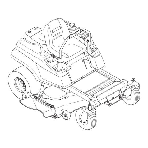
RZT Series Tractor — Mustang ZT50
WARNING
READ AND FOLLOW ALL SAFETY RULES AND INSTRUCTIONS IN THIS MANUAL
BEFORE ATTEMPTING TO OPERATE THIS MACHINE.
FAILURE TO COMPLY WITH THESE INSTRUCTIONS MAY RESULT IN PERSONAL INJURY.
TROY-BILT LLC, P.O. BOX 361131 CLEVELAND, OHIO 44136-0019
Printed In USA
Form No. 769-06530
(October 7, 2010)
Advertisement
Chapters
Table of Contents

Related Manuals for Troy-Bilt RZT MUSTANG ZT50


Summary of Contents for Troy-Bilt RZT MUSTANG ZT50
- Page 1 READ AND FOLLOW ALL SAFETY RULES AND INSTRUCTIONS IN THIS MANUAL BEFORE ATTEMPTING TO OPERATE THIS MACHINE. FAILURE TO COMPLY WITH THESE INSTRUCTIONS MAY RESULT IN PERSONAL INJURY. TROY-BILT LLC, P.O. BOX 361131 CLEVELAND, OHIO 44136-0019 Printed In USA Form No. 769-06530...
-
Page 2: Table Of Contents
Call a Customer Support Representative at (800) 828-5500 or (330) 558-7220 ◊ Write us at Troy-Bilt LLC • P.O. Box 361131 • Cleveland, OH • 44136-0019 If you have any problems or questions concerning the machine, phone a authorized Troy-Bilt service dealer or contact us directly. -
Page 3: Safe Operation Practices
Important Safe Operation Practices WARNING! This symbol points out important safety instructions which, if not followed, could endanger the personal safety and/or property of yourself and others. Read and follow all instructions in this manual before attempting to operate this machine. Failure to comply with these instructions may result in personal injury. - Page 4 A missing or damaged discharge cover can cause blade contact or thrown object injuries. Stop the blade(s) when crossing gravel drives, walks, or roads and while not cutting grass. Watch for traffic when operating near or crossing roadways. This machine is not intended for use on any public roadway.
- Page 5 Children Tragic accidents can occur if the operator is not alert to the presence of children. Children are often attracted to the machine and the mowing activity. They do not understand the dangers. Never assume that children will remain where you last saw them.
-
Page 6: Spark Arrestor
Check the blade(s) and engine mounting bolts at frequent intervals for proper tightness. Also, visually inspect blade(s) for damage (e.g., excessive wear, bent, cracked). Replace the blade(s) with the original equipment manufacturer’s (O.E.M.) blade(s) only, listed in this manual. “Use of parts which do not meet the original equipment specifications may lead to improper performance and compromise safety!”... -
Page 7: Safety Symbols
Safety Symbols This page depicts and describes safety symbols that may appear on this product. Read, understand, and follow all instructions on the machine before attempting to assemble and operate. Symbol READ THE OPERATOR’S MANUAL(S) Read, understand, and follow all instructions in the manual(s) before attempting to assemble and operate WARNING—... - Page 8 2 — s ectiOn peratiOn ractices...
-
Page 9: Assembly & Set-Up
Assembly & Set-Up Contents of Crate • One Lawn Tractor • One RZT Tractor Operator’s Manual Tractor Preparation Remove the upper crating material from the shipping pallet, and cut any bands or tie straps securing the tractor to the pallet. Use the lift handle to raise the deck to its highest position. - Page 10 Position Drive Control levers The drive control levers of the tractor are lowered for shipping purposes. The flange lock nuts, hex screws, and flat washers that normally secure the control levers in their operating position are unfastened and installed in the slotted holes of the control levers for shipment.
- Page 11 Lower Deck Discharge Chute Deflector WARNING! Never operate the mower deck without the chute deflector installed and in the down position. Check the mower deck for a shipping brace (with tag) that may be holding the chute deflector upward for shipment. If a brace is present, it must be removed before operating the tractor.
-
Page 12: Controls & Features
Controls and Features Parking Brake Throttle/Choke Control Hour Meter/ Indicator Panel Seat Adjustment Lever Fuel Tank Cap NOTE: References to LEFT, RIGHT, FRONT, and REAR indicate that position on the tractor when facing forward while seated in the operator’s seat. Deck Height Index The deck height index consists of six index notches located on the front/right of the seat box frame. -
Page 13: Ignition Switch
Ignition Switch The ignition switch is located on the RH console to the right of the operator’s seat. The ignition switch has three positions as follows: OFF - The engine and electrical system is turned off. ON - The tractor electrical system is energized. START - The starter motor will turn over the engine. - Page 14 Do not run the engine while this indicator is illuminated. Contact your Troy-Bilt dealer to have the tractor and engine inspected. NOTE: The oil pressure indicator may illuminate when the ignition switch is in the ON position, but should turn off when the engine is started.
-
Page 15: Operation
This tractor is equipped with a safety interlock system for the protection of the operator. If the interlock system should ever malfunction, do not operate the tractor. Contact your authorized Troy-Bilt Dealer. • The safety interlock system prevents the engine from... -
Page 16: Starting The Engine
Observe the hour meter / indicator panel. If the battery indicator light or oil pressure light come on, immediately stop the engine. Have the tractor inspected by your Troy-Bilt dealer. 5— O ectiOn peratiOn... -
Page 17: Driving The Tractor
Practice Operation (Initial Use) Operating a zero-turn tractor is not like operating a conventional type riding tractor. Although and because a zero turn tractor is more maneuverable, getting used to operating the control levers takes some practice. We strongly recommend that you locate a reasonably large, level and open “practice area”... - Page 18 To turn the tractor while driving forward, move the control levers as necessary so that one lever is rearward of the other. The tractor will turn in the direction of the rearward control lever. To turn to the left, move the left drive control lever rearward of the right lever.
- Page 19 To turn to the right while traveling in reverse, move the right drive control lever forward of the left lever. See Fig. 5-8. Rearward Right Turn Figure 5-8 The greater the fore-to-aft distance between the two levers, the sharper the tractor will turn. To execute a “pivot turn,”...
- Page 20 Periodically check the safety interlock circuits to ensure they are working properly. If a safety circuit is not working as designed, contact you Troy-Bilt dealer to have the tractor inspected. DO NOT operate the tractor if any safety circuit is not functioning properly.
-
Page 21: Maintenance & Adjustment
Maintenance & Adjustments Maintenance Schedule Check Engine Intake Screen/Cover Clean Hood/Dash Louvers Clean Battery Terminals Lube Front Pivot Axle and Caster Axles Clean Engine Cooling Fins Lube Front Deck Wheels Maintenance WARNING! Before performing any maintenance or repairs, disengage the PTO, move the drive control levers fully outward in the neutral position, engage the parking brake, stop the engine and remove the key to prevent unintended starting. - Page 22 Battery Maintenance • The battery is filled with battery acid and then sealed at the factory. However, even a “maintenance free” battery requires some maintenance to ensure its proper life cycle. • Spray the terminals and exposed wire with a battery terminal sealer, or coat the terminals with a thin coat of grease or petroleum jelly, to protect against corrosion.
- Page 23 Battery Storage When storing the tractor for extended periods, disconnect the negative battery cable. It is not necessary to remove the battery. All batteries discharge during storage. Keep the exterior of the battery clean, especially the top. A dirty battery will discharge more rapidly.
- Page 24 Adjustments Adjusting the Seat See the Assembly & Set-Up section for information on adjusting seat. Adjusting RH & LH Drive Control Levers The RH and LH drive control levers can be adjusted up or down and fore-and-aft for the comfort of the operator. The drive control levers can be placed in either of two height positions, and/or can be moved forward or rearward within the range of the slot in each control lever mounting bracket.
- Page 25 Front to Back Leveling. The front of the deck should be approximately than the rear of the deck. Adjust if necessary as follows: With the deck raised off of the ground, rotate the outer blades so that they are parallel to the frame of the tractor. If the side to side leveling was done correctly, measuring just the right blade should be acceptable to attain the correct back to front pitch of the deck.
-
Page 26: Service
If you have a recurring problem with blown fuses, have the tractor’s electrical system checked by your Troy-Bilt Service Dealer. Relays and Switches There are several safety switches in the electrical system. If a... - Page 27 Working from the middle of the tractor, pivot the idler bracket and movable idler pulley rearward away from the backside of the ‘V” belt just far enough to lift the belt up and over the idler pulley. See Fig. 7-3. Pull Idler Pulley Rearward...
-
Page 28: Deck Installation
Deck Installation To install the mower deck, proceed as follows: While holding the deck front hanger rod upward, carefully slide the deck underneath the right side of the tractor. While still holding the front hanger rod, slide the deck forward until the front hanger rod can be lowered into the slots of the front deck bracket. -
Page 29: Transmission Drive Belt
Mower Blade Care WARNING! Before performing any maintenance, place the PTO switch in the “OFF” position, engage the parking brake lever, turn the ignition key to the “OFF” position and remove the key from the switch. Protect your hands by using heavy gloves when handling the blades. - Page 30 Wheel rotation should stop. If it does not, contact your Troy-Bilt Service Dealer. If the rotation stops, adjust the control rod up or down as necessary to align with the hole in the transmission control arm.
-
Page 31: Troubleshooting
Troubleshooting Problem Excessive vibration Cutting blade loose or unbalanced. Damaged or bent cutting blade. Uneven cut Deck not leveled properly. Dull blade. Uneven tire pressure. Engine speed too low. Mower will not mulch grass (If Equipped w/Mulching Kit) Wet grass. Excessively high grass. -
Page 32: Replacement Parts
Replacement Parts Component Phone (800) 828-5500 to order replacement parts or a complete Parts Manual (have your full model number and serial number ready). Parts Manual downloads are also available free of charge at www.troybilt.com. Part Number and Description 759-3336 Spark Plug (RC12YC) KH-12-050-01-S Oil Filter KH-25-050-22-S1 Fuel Filter... - Page 33 Component Phone (800) 828-5500 to order replacement parts or a complete Parts Manual (have your full model number and serial number ready). Parts Manual downloads are also available free of charge at www.troybilt.com. Part Number and Description 734-04155 Deck Wheel 925-1707D Battery 751-10703A...
-
Page 34: Attachments & Accessories
Attachments & Accessories The following attachments and accessories are compatible with your Troy-Bilt tractor. See your Troy-Bilt dealer or the retailer from which you purchased your tractor for information regarding price and availability. Part Number 19A70004OEM OEM-190-193 19A-115-100 19A-116-100 190-117-100 Part 50”... - Page 35 Notes...
- Page 36 11— n ectiOn Otes...
- Page 37 11 — n ectiOn Otes...
-
Page 38: Warranties
FEDERAL and/or CALIFORNIA EMISSION CONTROL WARRANTY STATEMENT MTD Consumer Group Inc, the United States Environmental Protection Agency (EPA), and, for those products certified for sale in the state of California, the California Air Resources Board (CARB) are pleased to explain the emission (evaporative and/or exhaust) control system (ECS) warranty on your outdoor 2006 and later small off-road spark-ignited engine and equipment (outdoor equipment engine) In California, new outdoor equipment engines must be designed, built and equipped to meet the State’s stringent anti-smog standards (in other states, 1997 and later model year equipment must be designed, built, and equipped to meet the U.S. - Page 39 The repair or replacement of any warranted part otherwise eligible for warranty coverage may be excluded from such warranty coverage if MTD Consumer Group Inc demonstrates that the outdoor equipment engine has been abused, neglected, or improperly maintained, and that such abuse, neglect, or improper mainte- nance was the direct cause of the need for repair or replacement of the part.
- Page 40 MANUFACTURER’S LIMITED WARRANTY FOR The limited warranty set forth below is given by Troy-Bilt LLC with respect to new merchandise purchased and used in the United States and/or its territories and possessions, and by MTD Products Limited with respect to new merchandise purchased and used in Canada and/ or its territories and possessions (either entity respectively, “Troy-...
- Page 41 LEA Y RESPETE TODAS LAS NORMAS DE SEGURIDAD E INSTRUCCIONES INCLUIDAS EN ESTE MANUAL ANTES DE PONER EN FUNCIONAMIENTO ESTA MÁQUINA. SI NO RESPETA ESTAS INSTRUCCIONES PUEDE PROVOCAR LESIONES PERSONALES. TROY-BILT LLC, P.O. BOX 361131 CLEVELAND, OHIO 44136-0019 Impreso en Estados Unidos de América ción de problemas • Garantía...
- Page 42 Llame a un representante de Asistencia al Cliente al (800) 828-5500 ó (330) 558-7220 ◊ Escríbanos a Troy-Bilt LLC • P.O. Box 361131 • Cleveland, OH • 44136-0019 a todos los modelos. Reservamos el derecho de modificar las especificaciones de los productos, los diseños y el equipo estándar sin previo aviso y sin generar responsabilidad por...
-
Page 43: Medidas Importantes De Seguridad
Medidas importantes de seguridad ADVERTENCIA: La presencia de este símbolo indica que se trata de instrucciones importantes de seguridad que se deben respetar para evitar poner en peligro su seguridad personal y/o material y la de otras personas. Lea y siga todas las instrucciones de este manual antes de poner en funcionamiento esta máquina. - Page 44 Esté atento a la cortadora y a la dirección de la descarga de los aditamentos y no apunte a nadie. Nunca haga funcionar la cortadora de césped sin que estén colocados la cubierta de descarga o todo el colector de recortes de césped. No ponga las manos o los pies cerca de las piezas rotatorias o debajo de la plataforma de corte.
- Page 45 Haga que todos los movimientos en las pendientes sean lentos y graduales. No cambie repentinamente la velocidad ni la dirección. La aceleración o la reducción repentina de velocidad puede hacer que el frente de la máquina se levante y dé una voltereta hacia atrás, lo que podría producir lesiones graves.
- Page 46 Llene el tanque no más de ½ pulgada por debajo de la base del cuello del tapón de carga, para dejar espacio para la expansión del combustible. Vuelva a colocar la tapa de la gasolina y ajústela bien. Limpie el combustible que se haya derramado sobre el motor y el equipo.
- Page 47 Amortiguador de chispas ADVERTENCIA: Esta máquina está equipada con un motor de combustión interno y no debe ser utilizada en o cerca de un terreno agreste cubierto por bosque, malezas o hierba excepto que el sistema de escape del motor esté equipado con un amortiguador de chispas que cumpla con las leyes locales o estatales correspondientes (en caso de existir).
- Page 48 2 — M ección edidas de seguridad...
-
Page 49: Montaje Y Configuración
Montaje y Configuración Contenido del cajón • Un tractor corta césped • Un Manual del operador del tractor RZT Manual Preparación del tractor Retire el material de embalaje superior del pálet de embarque, y corte cualquier banda o tira que fije el tractor al pálet. Use la manija de elevación para levantar la plataforma a su posición más alta. - Page 50 Coloque las palancas de control de la transmisión en posición. Las palancas de control de la transmisión del tractor se bajan para el embarque. Las tuercas de seguridad con brida, los tornillos hexagonales y las arandelas planas que normalmente fijan las palancas de control en su posición operativa se aflojan e instalan en los orificios ranurados de las palancas de control para el envío.
- Page 51 Baje el deflector del canal de descarga de la plataforma ¡ADVERTENCIA! Nunca opere la plataforma de la cortadora sin el deflector de descarga instalado y en posición baja. Inspeccione la plataforma de la cortadora para ver si hay una traba de seguridad (con etiqueta) que puede estar sujetando el deflector del canal hacia arriba para el envío.
-
Page 52: Controles Y Características
Controles y Características Freno de mano Control del regulador/cebador Medidor horario/ Panel indicador Palanca de ajuste del asiento Tapón del tanque de combustible NOTA: Las referencias a IZQUIERDA, DERECHA, ADELANTE Y ATRÁS indican esa posición desde el asiento del operador en el tractor, mirando hacia adelante. - Page 53 Interruptor de encendido El interruptor de encendido está ubicado en la consola del lado derecho, a la derecha del asiento del operador. El interruptor de encendido tiene tres posiciones. OFF - Se apagan el motor y el sistema eléctrico. ON - Se activa el sistema eléctrico del tractor. ARRANQUE- El motor de arranque enciende el motor.
- Page 54 Características del panel indicador Indicador de batería Se ilumina y muestra brevemente el voltaje de la batería cuando el interruptor de encendido se coloca en posición "ON" (encendido). Se ilumina para indicar que el voltaje de la batería ha bajado por debajo de 11,5 (+0,5/-1,0) voltios de CC (el voltaje de la batería también se muestra en el medidor horario).
-
Page 55: Funcionamiento
Funcionamiento Seguridad general • RECIBA LAS INSTRUCCIONES - Lea este manual del operador en su totalidad. Aprenda a operar esta máquina CON SEGURIDAD. No se arriesgue a quedar expuesto a LESIONES o a la MUERTE. Solamente se debe permitir operar este tractor a quienes se hayan familiarizado a fondo con el uso del mismo. - Page 56 • Si el operador abandona su asiento con la potencia de arranque (PTO) enganchada, se encuentre o no colocado el freno de mano, el sistema de bloqueo de seguridad apaga el motor. NOTA: El interruptor de la potencia de arranque (PTO) se debe mover a la posición "OFF"...
- Page 57 Detención del motor Coloque el interruptor de la potencia de arranque (PTO) en posición "OFF" (apagado). Coloque las palancas de control de transmisión del lado derecho y del lado izquierdo totalmente hacia afuera, en posición neutral. Coloque el freno de mano. Mueva el control del regulador/cebador a distancia media entre las posiciones VELOCIDAD LENTA y VELOCIDAD RÁPIDA.
- Page 58 Conducción del tractor hacia adelante ¡ADVERTENCIA! Todos los movimientos de las palancas de control deben ser lentos y suaves. El movimiento abrupto de las palancas de control puede afectar la estabilidad del tractor y podría hacer que el tractor se voltee, con el resultado de lesiones graves o incluso la muerte del operador.
- Page 59 Conducción del tractor en marcha atrás ¡ADVERTENCIA! Siempre mire hacia atrás y hacia abajo a ambos lados del tractor antes de desplazarse marcha atrás. Siempre mire hacia atrás cuando se desplaza en marcha atrás. Mueva las dos palancas de control lenta y suavemente hacia atrás.
- Page 60 Giro de radio cero ¡ADVERTENCIA! Para realizar un giro de radio cero, el tractor SE DEBE DETENER. La realización de un giro de radio cero con el tractor en movimiento puede reducir significativamente el grado de control que se tenga sobre el mismo, y dará lugar a un grave deterioro del césped.
- Page 61 Uso de la plataforma de la cortadora ¡ADVERTENCIA! Asegúrese que el área donde se va a cortar esté libre de desechos, ramitas, piedras, cables u otros objetos que puedan ser arrojados por las cuchillas rotativas. NOTA: No enganche la plataforma de la cortadora cuando esté baja sobre el pasto.
-
Page 62: Mantenimiento Y Ajustes
Mantenimiento y Ajustes Calendario de mantenimiento Inspeccione la pantalla/cubierta de entrada del motor Inspeccione el nivel de aceite del motor Limpie los bornes de la batería Lubrique el eje de pivote delantero y los ejes de las rueditas Limpie las aletas de refrigeración del motor Lubrique las ruedas de la plataforma Mantenimiento ¡ADVERTENCIA! - Page 63 Mantenimiento de la batería • La batería se llena con ácido de batería y se sella en fábrica. Sin embargo, para asegurar un ciclo de vida adecuado es necesario realizar cierto mantenimiento en la batería, aún en el caso de las baterías 'sin mantenimiento'. •...
- Page 64 Después de mover el tractor, desenganche las dos varillas de derivación. Levante la varilla y guíe la brida de la varilla hacia atrás a través de la abertura circular más grande del ojo de llave, luego suelte la varilla. NOTA: El tractor no funciona si las varillas de derivación se encuentran en posición enganchada.
- Page 65 Para ajustar la altura de la palanca de control, proceda de la siguiente forma: Quite la tuerca de seguridad con brida, la arandela plana y el tornillo hexagonal que sujetan la palanca al soporte de pivote. Mientras sostiene la palanca de control para evitar que caiga, quite la tuerca de seguridad con brida de bulón hexagonal y el tornillo con reborde de la base de la palanca de control y soporte de pivote.
- Page 66 Nivelación de adelante hacia atrás La parte frontal de la plataforma debe estar aproximadamente a 1⁄4 de pulgada más abajo que la parte posterior de la plataforma. De ser necesario, realice un ajuste de la siguiente manera: Con la plataforma levantada del suelo, rote las cuchillas exteriores para que queden paralelas al marco del tractor.
-
Page 67: Servicio
Hay varias opciones de seguridad en el sistema eléctrico. Si una función del sistema de bloqueo de seguridad descritas anteriormente no funciona correctamente, el sistema eléctrico marcada por el concesionario de Troy-Bilt Servicio. Retiro de la plataforma Retire la plataforma de la cortadora de césped del tractor de la... - Page 68 Para aflojar la tensión de la correa con la polea loca. Usando la manija de elevación de la plataforma, levante la plataforma a la posición que le ofrece mayor recorrido horizontal de la correa entre las poleas locas de la plataforma y la polea de la potencia de arranque en la base del motor.
- Page 69 Con cuidado para evitar que la varilla de suspensión delantera caiga hacia atrás dentro de las ranuras del soporte de la plataforma, (desde el lado derecho) deslice lentamente la plataforma de corte hacia afuera desde abajo del tractor. Instalación de la plataforma Para instalar la plataforma de la cortadora de césped, proceda de la siguiente manera: Mientras sostiene la varilla de suspensión delantera hacia...
- Page 70 Cuidado de las cuchillas de la cortadora de césped ¡ADVERTENCIA! Antes de realizar cualquier tarea de mantenimiento, coloque el interruptor de la potencia de arranque (PTO) en la posición "OFF" (apagado), enganche la palanca del freno de mano, gire la llave de encendido a la posición "OFF" (apagado) y retire la llave del interruptor.
- Page 71 La rotación de la rueda debe parar. Si no hace, entrar en contacto con a su distribuidor autorizado del servicio del Troy-Bilt. Si la rotación para, ajuste la barra de control hacia arriba o hacia abajo cuanto sea necesario para alinear con el agujero en el brazo de control de la transmisión.
-
Page 72: Solución De Problemas
Solución de Problemas Problema Vibración excesiva Corte desigual La cortadora de césped no procesa los recortes como abono (si está equipada con kit de abono) Causa Cuchilla de corte floja o descentrada. Cuchilla dañada o curvada. La plataforma no está correctamente nivelada. - Page 73 Notas...
-
Page 74: Garantías
DECLARACIÓN FEDERAL y/o DE CALIFORNIA SOBRE GARANTÍAS EN EL CONTROL DE EMISIONES SUS DERECHOS Y OBLIGACIONES EN CUANTO A LA GARANTÍA MTD Consumer Group Inc, la Agencia de Protección Medioambiental de los Estados Unidos (EPA), y para aquellos productos certificados para su venta en el es- tado de California, el Departamento de los Recursos del Aire de California (CARB) se complacen en explicar la garantía que cubre al sistema de control (ECS) de emisiones (evaporativas y/o de escape) de su equipo y motor (motor de equipos de exteriores) de encendido por chispa para todo terreno, pequeño, de exteriores del año 2006 y años posteriores En California, los nuevos motores de equipos de exteriores deben estar diseñados, construidos y equipados para cumplir con las... - Page 75 Durante la totalidad del período de garantía del motor y equipo para todo terreno arriba mencionado, MTD Consumer Group Inc mantendrá un suministro de piezas bajo garantía suficiente para satisfacer la demanda esperada de tales piezas. Cualquier pieza de reemplazo se podrá usar para el cumplimiento del mantenimiento o las reparaciones bajo garantía y se suministrarán sin cargo para el propietario.
- Page 76 Las disposiciones de esta garantía cubren el recurso de reparación única y exclusiva que surge de la venta. Troy-Bilt no se hará responsable de ninguna pérdida o daño incidental o resultante, incluyendo sin limitación, los gastos incurridos para los servicios de mantenimiento del césped, o los gastos de arrendamiento para...