
Summary of Contents for Pentair Pool Products Fleck SXT
- Page 1 SXT Timer Supplemental Service Manual IMPORTANT: Fill in Pertinent Information on Page 3 for Future Reference...
-
Page 2: Table Of Contents
Table of Contents Job Specification Sheet ............................3 Timer Features ..............................4 Timer Operation ..............................6 Master Programming Mode Chart ......................... 8 Master Programming Mode ..........................10 User Programming Mode ............................ 17 Diagnostic Programming Mode ........................... 19 2510 / 2750 / 2850s Timer Assembly ........................21 9000 / 9100 / 9500 Twin Tank Timer Assembly .................... -
Page 3: Job Specification Sheet
Job Specification Sheet Job Number: __________________ Model Number: ________________ Water Hardness: ___________________ ppm or gpg Capacity Per Unit: ______________ Mineral Tank Size: ___________ Diameter: ___________ Height: Salt Setting per Regeneration: _____________________________________________ Type of Timer: 7 Day or 12 Day B. Meter Initiated 2. Downflow: Upflow Upflow Variable... -
Page 4: Timer Features
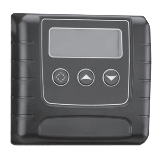
Timer Features Parameter Data Display Display Indicator Error/ Information Icon Flow Indicator Service Icon x1000 Indicator Programming Icon Extra Cycle Down Button Button Button Features of the SXT: • Power backup that continues to keep time and the passage of days for a minimum of 48 hours in the event of power failure. - Page 5 Timer Features Queueing a Regeneration 1. Press the Extra Cycle button. The service icon will flash to indicate that a regeneration is queued. 2. To cancel a queued regeneration, press the Extra Cycle button. Regenerating Immediately Press and hold the Extra Cycle button for five seconds. Page 5...
-
Page 6: Timer Operation
Timer Operation Meter Immediate Control A meter immediate control measures water usage and regenerates the system as soon as the calculated system capacity is depleted. The control calculates the system capacity by dividing the unit capacity (typically expressed in grains/unit volume) by the feedwater hardness and subtracting the reserve. Meter Immediate systems generally do not use a reserve volume. - Page 7 Timer Operation Control Operation During A Power Failure The SXT includes integral power backup. In the event of power failure, the control shifts into a power-saving mode. The control stops monitoring water usage, and the display and motor shut down, but it continues to keep track of the time and day for a minimum of 48 hours.
-
Page 8: Master Programming Mode Chart
Master Programming Mode Chart Master Programming Options Abbreviation Parameter Option Options Abbreviation Gallons Display Format Liters Cubic Meters St1b Standard Downflow/Upflow Single Backwash St2b Standard Downflow/Upflow Double Backwash Fltr Filter Valve Type UFbF Upflow Brine First 8500 TwinFlo100SXT Othr Other Meter (Flow) Delayed Meter (Flow) Immediate Control Type... - Page 9 Master Programming Mode Chart Master Programming Options Current Day The Current day of the week t0.7 3/4" Turbine Meter P0.7 3/4" Paddle Wheel Meter t1.0 1" Turbine Meter Flow Meter Type P1.0 1" Paddle Wheel Meter t1.5 1.5" Turbine Meter P1.5 1.5"...
-
Page 10: Master Programming Mode
Master Programming Mode When the Master Programming Mode is entered, all available option setting displays may be viewed and set as needed. Depending on current option settings, some parameters cannot be viewed or set. Setting the Time of Day 1. Press and hold either the Up or Down buttons until the programming icon replaces the service icon and the parameter display reads TD. - Page 11 Master Programming Mode 2. Valve Type (Display Code VT) Press the Extra Cycle button. Use this display to set the Valve Type. The Valve Type setting specifies the type of cycle that the valve follows during regeneration. Note that some valve types require that the valve be built with specific subcomponents.
- Page 12 Master Programming Mode 5. Tank in Service (Display Code TS) Press the Extra Cycle button. Use this display to set whether tank one or tank two is in service. This option setting is identified by “TS” in the upper left hand corner of the screen. This parameter is only available if the number of tanks has been set to 2.
- Page 13 Master Programming Mode 8. Reserve Selection (Display Code RS) Press the Extra Cycle button. Use this display to set the Safety Factor. Use this display to select the type of reserve to be used in your system. This setting is identified by “RS” in the upper left-hand corner of the screen. The reserve selection parameter is only available if the control type has been set to one of the metered options.
- Page 14 Master Programming Mode 11. Day Override (Display Code DO) Press the Extra Cycle button. Use this display to set the Day Override. This setting specifies the maximum number of days between regeneration cycles. If the system is set to a timer-type control, the day override setting determines how often the system will regenerate.
- Page 15 Master Programming Mode 14. Day of Week Settings Press the Extra Cycle button. Use this display to set the regeneration schedule for a system configured as a Day of Week control. The different days of the week are identified as D1, D2, D3, D4, D5, D6, and D7 in the upper left-hand corner of the display.
- Page 16 Master Programming Mode 17. Meter Pulse Setting (Display Code K) Press the Extra Cycle button. Use this display to specify the meter pulse setting for a non-standard flow meter. This option setting is identified by “K” in the upper left-hand corner of the screen. Use the Up and Down buttons to enter the meter constant in pulses per unit volume.
-
Page 17: User Programming Mode
User Programming Mode User Programming Mode Options Abbreviation Parameter Description Day Override The timer’s day override setting Regeneration Time The time of day that the system will regenerate (meter delayed, timeclock, and day-of-week systems) Feed Water Hardness The hardness of the inlet water - used to calculate system capacity for metered systems Reserve Capacity... - Page 18 User Programming Mode 5. Press the Extra Cycle button. Use this display to adjust the Fixed Reserve Capacity. This option setting is identified by “RC” in the upper left-hand Corner of the screen. 6. Press the Extra Cycle button. Use this display to set the Current Day of the Week. This option setting is identified by “CD”...
-
Page 19: Diagnostic Programming Mode
Diagnostic Programming Mode Diagnostic Programming Mode Options Abbreviation Parameter Description Flow Rate Displays the current outlet flow rate Peak Flow Rate Displays the highest flow rate measured since the last regeneration Hours in Service Displays the total hours that the unit has been in service Volume Used Displays the total volume of water treated by the unit Reserve Capacity... - Page 20 Diagnostic Programming Mode 6. Press the Up button. Use this display to view the Reserve Capacity. This option setting is identified by “RC” in the upper left hand corner of the screen. 7. Press the Up button. Use this display to view the Software Version. This option setting is identified by “SV” in the upper left hand corner of the screen.
-
Page 21: 2510 / 2750 / 2850S Timer Assembly
2510 / 2750 / 2850s Timer Assembly 9C 9D Item No. Quantity Part No. Description 1 ....1 ....13881 ......Bracket, Hinge Timer 3 ....1 ....14265 ......Clip, Spring 4 ....1 ....27172 ......Stand-off, Timer, 2510SXT, 2750SXT 5 ....1 ....21363 ......Screw, Hex HD, M4 X 12 MM 7 .... -
Page 22: 9000/9100/9500 Twin Tank Timer Assembly
9000/9100/9500 Twin Tank Timer Assembly Item No. Quantity Part No. Description 1 ....1 ....13881 ......Bracket, Hinge Timer 2 ....2 ....11384 ......Screw, Phillips, 6-32 X 1/4 3 ....1 ....42732 ......Bracket, Timer, 9000SXT 4 ....2 ....13296 ......Screw, Hex Washer Hd, 6-20 X 1/2 5 .... -
Page 23: 3/4" Plastic Turbine Meter Assembly
3/4" Plastic Turbine Meter Assembly Item No. Quantity Part No. Description 1 ....1 ....19791-01 ....Meter Cable Assy, Turbine/SXT 2 ....2 ....19569 ......Clip, Flow Meter 3 ....2 ....13314 ......Screw, Slot Ind Hex, 8-18 x .60 For Assembly Numbers, See the Back of this Manual Page 23... -
Page 24: Meter Assembly
Meter Assembly 60086_REVD_60086-50 Item No. Quantity Part No. Description 1 ....1 ....13874 ......Body, Meter, 5600 2 ....1 ....14715 ......Gear Assy, Electronic Meter Cap 3 ....1 ....41055 ......Plate, Intermediate 4 ....1 ....13847 ......O-ring, -137, Std, Meter 5 ....5 ....17798 ......Screw, Slot Hex Washer Head 6 ....1 .... -
Page 25: 3/4" Brass Paddle Meter Assembly
3/4" Brass Paddle Meter Assembly Item No. Quantity Part No. Description 1 ....1 ....11206 ......Gasket, Fitting 2 ....1 ....13942 ......Retainer, Nut 3 ....1 ....11207 ......Nut, Special, Quick Connect 4 ....1 ....13906 ......Body, Meter, 3/4" 5 .... -
Page 26: 1" Brass Paddle Meter Assembly
1" Brass Paddle Meter Assembly Item No. Quantity Part No. Description 1 ....1 ....14959 ......Body, Meter, 2750 2 ....1 ....13882 ......Post, Meter Impeller 3 ....1 ....13509 ......Impeller, Meter 4 ....1 ....13847 ......O-ring, -137, Std/560CD, Meter 5 .... -
Page 27: Inline Plastic Turbine Meter Assembly
Inline Plastic Turbine Meter Assembly Item No. Quantity Part No. Description 1 ....1 ....17542 ......Flow Straightener 2 ....2 ....40576 ......Clip, H, Plastic, 7000 3 ....1 ....40577 ......Turbine Meter Assy, 7000 4 ....1 ....41555 ......Body, Remote Meter 5 .... -
Page 28: 1-1/2" Brass Paddle Meter Assembly
1-1/2" Brass Paddle Meter Assembly Item No. Quantity Part No. Description 1 ....1 ....17569 ......Body, Meter, 2850/9500 2 ....1 ....13882 ......Post, Meter Impeller 3 ....1 ....13509 ......Impeller, Meter 4 ....1 ....13847 ......O-ring, -137, Std/560CD, Meter 5 .... -
Page 29: 3/4", 1" Or 1-1/2" Paddle Wheel Meter Cap Assembly
3/4", 1" or 1-1/2" Paddle Wheel Meter Cap Assembly Item No. Quantity Part No. Description 1 ....1 ....14716 ......Meter Cap Assy, NT 2 ....1 ....19121-01 ....Meter Cable Assy, SXT, Paddle 6700XTR 3 ....1 ....13847 ......O-ring, -137, Std/560CD, Meter 4 .... -
Page 30: 2510Sxt Wiring Diagram
2510SXT Wiring Diagram 42741 Page 30... -
Page 31: 2750Sxt / 2850Sxt Wiring Diagram
2750SXT / 2850SXT Wiring Diagram 42742 Page 31... -
Page 32: 9000Sxt / 9100Sxt / 9500Sxt Wiring Diagram
9000SXT / 9100SXT / 9500SXT Wiring Diagram 42743 Page 32... -
Page 33: Troubleshooting
Troubleshooting Error Codes Note: Error codes appear on the In Service display. Error Error Type Cause Reset and Recovery Code Cam Sense The valve drive took longer Unplug the unit and examine the powerhead. Verify Error than 6 minutes to advance to that all cam switches are connected to the circuit the next regeneration position. -
Page 34: Service Assemblies
Service Assemblies Meter: 60086-50 ..Meter Assy, 3/4", Electronic 2510/6600/6700 60613 ..... Meter Assy, 2750 Electronic 1" 60613-20 ..Meter Assy, 2750, Electronic 1" BSP/Metric 60613NP ..Meter Assy, 2750, Electronic 1" Nickel Plated 60614....Meter Assy, 2850/9500, Electronic 1-1/2" Meter 60614NP .. - Page 35 Notes Page 35...
- Page 36 P/N 42713 Rev. E 12/04/09...