Makita MLT100 Technical Information
260mm (10-1/4"), 255mm (10")
Hide thumbs
Also See for MLT100:
- Instruction manual (85 pages) ,
- Instruction manual (14 pages) ,
- Instruction manual (73 pages)
Table of Contents
Advertisement
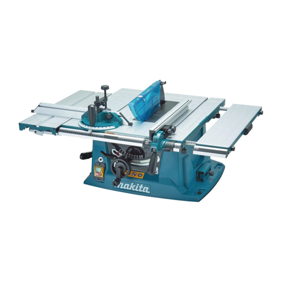
MLT100
Table Saw 260mm (10-1/4")*
Table Saw 255mm (10")*
*1 for European countries
*2 for all countries except European countries
Model MLT100 has been developed as a cost-competitive sister
model of Models 2704/2705.
The machine for USA and Canada features blade guard in
compliance with the latest UL Standards
Voltage (V)
Current (A)
110
120
230
Specifications
Diameter
Saw blade:
mm (")
Hole diameter
No load speed: min.-
=rpm
1
Bevel cutting capacity: degrees
Cutting capacities: mm (")
Soft start
Electric brake
Double insulation
Power supply cord: m (ft)
Net weight*: kg (lbs)
*Weight according to EPTA-Procedure 01/2003
TCT saw blade
Wrench
Dust bag
Holder
Note: The standard equipment may vary by country or model variation.
TCT saw blade
2
.
Cycle (Hz)
4.1
50/60
4.0
50/60
2.0
50/60
Area
European countries
260 (10-1/4)
30 (1-3/16)
at 90 degrees
93 (3-5/8)
64 (2-1/2)
at 45 degrees
Vise assembly
Triangular rule
Set plate
1
Note: MLT100 for USA and Canada differs from
the image shown above in some details.
Continuous Rating (W)
Input
430
N/A
430
USA, Canada
Mexico, Panama
15.88 (5/8)
4,300
0 to 45
Yes: all high voltage areas except UK and those in
Asia No: UK, Asia, all low voltage areas
Yes
Yes
2.5 (8.2)
34.8 (76.7)
1 / 24
June 2016
W
H
Dimensions: mm (")
Length (L)
726 (28-1/2)
Width (W)
984 (38-3/4)
Height (H)
333 (13-1/8)
Max Output (W)
Output
220
340
220
340
220
340
Other countries
255 (10)
30 (1-3/16)
90.5 (3-9/16)
63 (2-1/2)
L
Advertisement
Table of Contents

Related Manuals for Makita MLT100


Summary of Contents for Makita MLT100
- Page 1 Table Saw 255mm (10")* *1 for European countries *2 for all countries except European countries Model MLT100 has been developed as a cost-competitive sister Note: MLT100 for USA and Canada differs from model of Models 2704/2705. the image shown above in some details.
- Page 2 REPAIR MANUAL Table Saw MLT100 Version: A 2 / 24...
- Page 3 CONTENTS [1]NECESSARY REPAIRING TOOLS・・・・・4 [2]LUBRICATION・・・・・・・・・・・・・5 [3]DISASSEMBLY/ASSEMBLY・・・・・・・7 [4]ADJUSTMENT・・・・・・・・・・・・・19 [5]Circuit diagram, wiring diagram・・・・・・・23 3 / 24...
- Page 4 Repair CAUTION: Repair the machine in accordance with “Instruction manual” or “Safety instructions”. [1]NECESSARY REPAIRING TOOLS Code NO. Description Use for 1R034 Bearing Setting plate 12.2 Press-fitting Bearing 6001 to Rotor 1R036 Bearing Setting plate 17.2 Assembling Bearing 6004 to output shaft 1R080 Arbor Press Press-fitting Bearing...
- Page 5 [2]LUBRICATION Apply lubricant to the portions designated with the following arrows to protect parts and product from unusual abrasion. Gear box section Frame turn section Up/down gear and the bars 5 / 24...
- Page 6 6 / 24...
- Page 7 Repair [3]DISASSEMBLY/ASSEMBLY [3]-1.Blade (1) Take off 6pcs of M4X8 cross head screw and remove the table insert (2)Hold the outer flange with the wrench and loosen the hex nut counterclockwise with the wrench. (3) Remove the out flange and change the blade. 7 / 24...
- Page 8 (4) The ring on the spindle --For all countries other than Europe, blade bore size 25.4mm. --For European countries, blade bore size 30mm. 8 / 24...
- Page 9 Repair [3]Disassembly/Assembly [3]-2.Blade guard (1) Before installing/disassembly the blade guard, adjust the depth of cut to its maximum elevation. Remove the table insert as previous 3.1.1. (2)Insert the riving knife into the blade guard mounting portion, and tighten the 2pcs of M6 H.S.bolts by allen wrench. (3) Place the blade guard into the groove on the riving knife.
- Page 10 10 / 24...
- Page 11 Repair [3]Disassembly/Assembly [3]-3.Switch (1)Remove the screws and take out the swtich. (2)Change the switch. EU switch Safety switch 11 / 24...
- Page 12 Repair [3]Disassembly/Assembly [3]-4.Motor (1)Remove the up blade guard, blades first. (2)Remove the screws in the bottom and take off the bottom plate. (3)Remove the switch (4)Remove the pointer, elevating handle, wheel, lock handle, locking rod. 12 / 24...
- Page 13 (5)Removing the dust cover. (6)Removing the limited screw on the transparent plate. (7)Removing the screws from cabinet. 13 / 24...
- Page 14 (8)Remove the frame bracket. (9)Remove the blade cover. 14 / 24...
- Page 15 (10)Remove the elevating bracket screw. (11)Remove the protection cover. (12)Remove the screws on the elevation bar. 15 / 24...
- Page 16 16 / 24...
- Page 17 Repair [3]Disassembly/Assembly [3]-5.Stator (1)Remove 2pcs of brushes; (2) Remove 4pcs screws. (3)Take off the motor housing together with the stator Repair [3]Disassembly/Assembly [3]-6.Rotor (1) Take off the rotor from the gear box arm by hammer. 17 / 24...
- Page 18 (2)Take the rotor (3)Rotor assembly Repair [3]Disassembly/Assembly [3]-7.Gear (1) Remove the screw 18 / 24...
- Page 19 (2) Take off the gear wheel assy. Repair [4]Adjustment [4]-1.Adjustment the riving knife align with the blade (1) Use the Allen wrench to loosen the M6 bolts(6). (2) Use the ruler to check and adjust the riving knife alignment. 19 / 24...
- Page 20 Repair [4]ADJUSTMENT [4]-2.Adjustment the rip fence (1)Raise the blade to the up position and set the rip fence. (2) Use hex wrench to loosen the bracket and adjustment. (3)Make sue the rip fence parallel to the blade then tightening bolt. 20 / 24...
- Page 21 Repair [4]ADJUSTMENT [4]-3.Adjustment for blade parallel (1)Remove the table insert first and loosen the two screws under the front table. (2)Use the screw driver to adjust the frame to adjust the blade parallel, and lock the two bolts. 21 / 24...
- Page 22 Repair [4]ADJUSTMENT [4]-3.Adjustment blade bevel positive stops. (1)Use the wrench to adjust the setting screw on the table for 90°. (2)Use the wrench to adjust the setting screw on the table for 45°. 22 / 24...
- Page 23 Repair [5]Circuit diagram, wiring diagram [5]-1.220-240V/50HZ,110V/50HZ area where EMC required. 23 / 24...
- Page 24 Repair [5]Circuit diagram, wiring diagram [5]-2.110-120V/60HZ, 24 / 24...