
Related Manuals for Toshiba Surveillix XVR16-60-X


Summary of Contents for Toshiba Surveillix XVR16-60-X
-
Page 1: User Manual
Digital Video Recorder User Manual XVR4-120-X model no. XVR16-60-X XVR16-120-X Please carefully read these instructions before using this product. Save this manual for future use. 27812AE... - Page 2 No part of this documentation may be reproduced in any means, electronic or mechanical, for any purpose, except as expressed in the Software License Agreement. Toshiba shall not be liable for technical or editorial errors or omissions contained herein. The information in this document is subject to change without notice.
-
Page 3: Limited Warranty
Accordingly, Toshiba disclaims any and all liability arising out of the use of the product in any critical applications. -
Page 4: Important Safeguards
Object and Liquid Entry Points – Never insert foreign objects into the XVR unit, other than the media types approved by Toshiba, as they may touch dangerous voltage points or short-out parts that could result in a fire or electrical shock. Never spill liquid of any kind on the product. -
Page 5: Notes On Handling
IMPORTANT SAFEGUARDS, continued Damage Requiring Service – Unplug the unit from the outlet and refer servicing to qualified service personnel under the following conditions: When the power-supply cord or plug is damaged. If liquid has been spilled, or objects have fallen into the unit. If the unit has been exposed to rain or water. -
Page 6: Notes On Maintenance
NOTES ON CLEANING Use a soft dry cloth for cleaning. For stubborn dirt, soak the cloth in a weak detergent solution, wring well and wipe. Use a dry cloth to wipe it dry. Do not use any type of solvent, such as thinner and benzene, as they may damage the surface of the XVR unit. If using a chemical saturated cloth to clean the unit, follow that product’s instructions. -
Page 7: Explanation Of Graphical Symbols
WARNING TO REDUCE THE RISK OF ELECTRICAL SHOCK, DO NOT EXPOSE THIS APPLIANCE TO RAIN OR MOISTURE. DANGEROUS HIGH VOLTAGES ARE PRESENT INSIDE THE ENCLOSURE. DO NOT OPEN THE CABINET. REFER SERVICING TO QUALIFIED PERSONNEL ONLY. CAUTION C A U T I O N RISK OF ELECTRIC SHOCK DO NOT OPEN CAUTION: TO REDUCE THE RISK OF ELECTRIC SHOCK,... -
Page 8: Rack Mount Instructions
RACK MOUNT INSTRUCTIONS Elevated Operating Ambient – If installed in a closed or multi-unit rack assembly, the operating ambient temperature of the rack environment may be greater than room ambient. Therefore, consideration should be given to installing the equipment in an environment compatible with the maximum ambient temperature (Tma) specified by the manufacturer. -
Page 11: Table Of Contents
PREFACE... 1 About this Guide ... 1 Technician Notes ... 1 INTRODUCTION ... 2 Product Description... 2 Features... 3 CONTROLS AND CONNECTIONS ... 5 System Specifications ... 6 Front Panel Controls and LEDs ... 7 Rear Panel Connectors... 8 16 Channel ... 8 4 Channel... - Page 12 Setup Screen Overview ... 34 Camera Setup ... 35 Setup New Camera ... 35 HVR Registration (XVR Upgrade Option)... 36 Obtaining the Unlock Code... 36 Unlocking a New Network Camera... 38 Connecting a Network Camera ... 38 Motion Setup... 39 Create a Motion Region ...
- Page 13 SEARCH... 63 Search Overview... 64 Play Controls ... 64 Adjust the Brightness of an Image... 65 Zooming In On an Image... 65 Zooming In On a Portion of an Image ... 65 Open Video from Saved Location... 65 Time Sync ... 65 Clean Image ...
- Page 14 Specifying Scheduled Backup Drives ... 87 LAN / ISDN / PSTN CONNECTIONS ... 89 lan overview ... 90 connecting to a lan using tcp/ip... 90 Configuring TCP/IP Settings ... 90 EVENT SENTRY ... 93 Overview ... 94 Setup Event Sentry ... 94 Add Email Notification Filters ...
- Page 15 NOTES:...
- Page 16 NOTES:...
-
Page 17: Preface
Only authorized personnel should attempt to repair this unit. Toshiba reserves the right to make changes to the XVR units represented by this manual without notice. The following text and symbols mark special messages throughout this guide: NOTE: Text set off in this manner indicates topics of interests that can help the user understand the product better. -
Page 18: Introduction
INTRODUCTION PRODUCT DESCRIPTION A Surveillix XVR is simply a server that performs as a High Definition Digital Recorder. By utilizing the many features of a computer, including processing power, storage capacity, graphics compression, and security features, the XVR unit is more powerful than the analog recorders of the past. -
Page 19: Features
FEATURES Toshiba’s Surveillix XVRs include the following new features: • Optimized and Designed for Microsoft Windows XP Embedded • Record up to 120 PPS • Up to 16 Camera Inputs • Supports up to 4 Relay Outputs on Alarm Activation •... - Page 20 NOTES:...
-
Page 21: Controls And Connections
CONTROLS AND CONNECTIONS This chapter includes the following information: • Input / Output Connector Locations • Front Panel Controls and LEDs • Rear Panel Connectors... -
Page 22: System Specifications
SYSTEM SPECIFICATIONS Surveillix™ state-of-the-art High Definition Digital Recorders are housed in a high performance and versatile 3U Rack-Mount case allowing easy storage of multiple XVRs for enterprise applications. Every Surveillix XVR unit comes equipped with the latest technology: Intel® Celeron D 3.2Ghz Processor 10/100 Network Interface 512 MB of System Memory DVD±RW Recorder... -
Page 23: Front Panel Controls And Leds
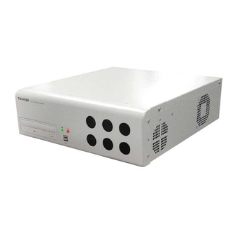
FRONT PANEL CONTROLS AND LEDS The front panel of the XVR unit contains the devices that will be commonly used for data removal, retrieval, and backup replacement. The most common components and buttons are shown below: Hard Drive Activity LED Power LED DVD±RW Drive USB Ports... -
Page 24: Rear Panel Connectors
REAR PANEL CONNECTORS The rear panel of the XVR unit contains the connectors used to attach cameras, sensors, and relays to the XVR. Below are diagrams that outline the location and description of each connector: 16 Channel AC Power Connector Adapter for BNC Looping Output Cable BNC Connectors for Video Input Sensors Inputs... -
Page 25: Channel
4 Channel AC Power Connector PS/2 Mouse Input PS/2 Keyboard Input DB-9 Serial Input SVGA Output LPT Parallel Printer Port BNC Connectors for Video Input Audio/Spot RJ-45 Network Jack Monitor Output RS-485 Interface Audio USB Ports • Line In – line level •... - Page 26 NOTES:...
-
Page 27: Getting Started
GETTING STARTED This chapter includes the following information: • Included Components • Setting the XVR Hardware • Optional Components... -
Page 28: Identifying Included Components
IDENTIFYING INCLUDED COMPONENTS XVRs come with a mouse, keyboard and selected software and cables. Identify the following components to make sure Surveillix™ everything has been properly included with the new XVR unit. If any of the following items are missing, contact the dealer to arrange a replacement. -
Page 29: Optional Components
OPTIONAL COMPONENTS To fully utilize the XVR unit’s potential; several optional Surveillix components are listed below. Contact the dealer for more information. GB-NIC Gigabit Network Card Increase data transfer rate with a faster network card SCSI-UPG SCSI Card Use to connect external storage devices 16-AUD 16 Channel Audio Card (compatible with 16 Channel model only) Increase audio recording capacity... -
Page 30: Keyboard Setup
KEYBOARD SETUP To attach the keyboard to the XVR unit, plug the end of the Keyboard into the keyboard PS/2 Port located on the back of the machine. The keyboard PS/2 Port can be identified by the purple color. Refer to the Rear Panel Connectors diagram for more information. MOUSE SETUP To attach the mouse to the XVR unit, plug the end of the mouse into the mouse PS/2 Port located on the back of the machine. -
Page 31: Monitor Setup
MONITOR SETUP The XVR has the following connection available to attach a monitor. Attach the monitor or monitors to the rear of the XVR unit using the cable supplied by the monitor manufacturer. Refer to the monitor manual for detailed information on how to setup and use it. NOTE: The monitor must be capable of having a screen resolution of 1024 x 768 and display colors of at least 32 Bit POWER SETUP WARNING:... -
Page 32: Connecting A Video Source To The Xvr
CONNECTING A VIDEO SOURCE TO THE XVR There are different types of Video Sources that can be plugged into the XVR unit including DVD players, VHS players, and CCTV Cameras. The back of the XVR unit contains up to 16 video inputs depending on the XVR model. The connectors use the BNC standard. -
Page 33: Connecting Sensors To The Xvr
CONNECTING SENSORS TO THE XVR Each XVR unit may have up to 16 Sensor inputs. These inputs can be used with devices such as infrared devices, motion device, glass breakage alarms, door and window trips, and many more. The Sensors can be set to Normally Open or Normally Closed inside the software. -
Page 34: Connecting Control Outputs To The Xvr
CONNECTING CONTROL OUTPUTS TO THE XVR Each XVR unit may have up to 4 Control Outputs. These outputs can be used to trigger devices such as Sirens, Phone Dialers, Lights, and any other relay activated device. There is no power supplied to the ports. Use an external power supply if necessary. 16 Channel 4 Channel Use 12V, below 300mA. -
Page 35: Looping Outputs
LOOPING OUTPUTS The 16 Channel XVR unit may have up to 16 Looping outputs. Depending on the destination of the outputs, each output may have to be terminated. The outputs are located on the BNC Connector Cable. Attach the cable to the input for the BNC Connector Cable highlighted below. -
Page 36: Connecting A Ptz Camera
CONNECTING A PTZ CAMERA Setting up a PTZ Camera is simple. The XVR unit comes preassembled with an internal PTZ adapter. The cabling may be run up to 4,000 ft using 22 Gauge Twisted Pair. It is important to understand how the PTZ connects to the XVR. The XVR outputs an RS-232 signal and converts in to an RS-422/485 signal which is then sent to the PTZ camera. -
Page 37: Turning On The Xvr
TURNING ON THE XVR Turn on the monitor and any external peripherals (ex. Printers, External Storage Devices, etc.) connected to the XVR unit. Turn on the Power Switch located in the rear of the XVR unit. The XVR will run a series of self-tests. After two or three minutes, a series of messages may be displayed as the various hardware and software subsystems are activated. - Page 38 NOTES:...
-
Page 41: Dvr Basics
DVR BASICS This chapter includes the following information: • Turning the DVR on and off • Becoming familiar with the Display screen • Defining Screen Divisions... -
Page 42: Turning On The Dvr
TURNING ON THE DVR Once the cables and adapters have been properly connected it is time to turn on the power. To turn on the power follow these steps: Turn on the monitor and any external peripherals (ex. Printers, External Storage Devices, etc.) connected to the DVR unit. Turn on the Secondary Power Switch located in the rear of the DVR unit. -
Page 43: Using The Dvr Utility
USING THE DVR UTILITY Exporting DVR Settings Exporting DVR settings can help configure multiple DVRs quickly or reconfigure a unit that has failed. Some things must be kept in mind when using this feature. You cannot use this function on: •... -
Page 44: Changing Video Format
Changing Video Format Exit to Windows by clicking the Exit Button on the Main Display Screen and selecting Restart in Windows Mode. (See the Display Screen section later in this chapter). Click Start > Programs > Surveillix > VFormat. Select the appropriate video setting from the list in the Video Setting Section – NTSC or PAL. Click Set Click the OK Button to close the VFormat Utility. -
Page 45: Camera View
CAMERA VIEW The Camera status for each camera is displayed next to the Camera number (or name) on the Video Display Area. The following are Camera No. and Name Recording Status Indicator The camera status for each camera is displayed in the upper right corner on the Video Display Area. The following are the different states for each camera: Recording Displayed when the camera is currently being recorded to the DVR unit. -
Page 46: Screen Division Buttons
SCREEN DIVISION BUTTONS The Screen Division Buttons allow you to view cameras in groups such as two by two, three by three and four by four. The button options are shown below. 1st Four Cameras View – Displays cameras 1-4 in the Video Display Area. To return to a different Multi-Camera View, select a different Screen Division option from the Screen Division Menu. -
Page 49: Setup Options
SETUP OPTIONS This chapter includes the following information: • Setup Overview • Channels • Color • Schedule • Speed • Motion Detect • Password • Pan/Tilt • Audio... -
Page 50: Setup Overview
SETUP OVERVIEW The Setup options allow you to optimize your DVR unit by adjusting things like camera names, reboot schedules, recording schedules and more. It is extremely important that you setup your DVR correctly for several reasons. • Recording Schedules – By optimizing the recording schedule you can increase the amount of pertinent recorded video that is saved on the DVR and keep it longer. -
Page 51: Camera Setup
CAMERA SETUP Selected Camera Display Setup New Camera Attach camera to the rear of the DVR chassis. Click the Setup Button on the Main Display Screen. Click the Camera Setup Button to open the Camera Setup Display. Select the channel that corresponds with the new camera from the Select Camera Drop Down Menu. Enter a name for the camera in the Camera Name Field. -
Page 52: Hvr Registration (Xvr Upgrade Option)
Have the following information available before registering the HVR upgrade. HVR Software Serial Number: The product Serial Number is the unique number that Toshiba provided with the software purchase. System ID: The System ID is a number generated by the Surveillix unit. This is a unique code generated using the MAC address of the computer running the software. - Page 53 Once validated, the user will be provided with the Unlock Code Print the page and save for later reference...
-
Page 54: Unlocking A New Network Camera
Enter Setup Enter Camera Setup Click the Registration Button Enter the Unlock Code generated by the Toshiba Registration Site into the “new serial number” field Click Add a serial number Once the new serial number has been added to the list,... -
Page 55: Motion Setup
MOTION SETUP The DVR unit allows the user to adjust several different Motion Settings and create motion detection regions. Display full screen video pop up on motion event Beep on motion event Display full screen video pop up on sensor event Schedule recording at a regular specified interval Create a Motion Region... -
Page 56: Activating An Alarm On A Motion Event
Activating an Alarm on a Motion Event In the Motion Setup window, select a camera to edit from the drop down menu Create a motion area. Select the Alarm Output box. Select a Control Output to activate for the selected camera. Select the duration to activate the Alarm when a motion event occurs. -
Page 57: Frame Setup Overview
FRAME SETUP OVERVIEW The Frame Setup Menu allows configuration of the PPS, resolution, quality, and sensitivity of camera channels. When configuring the PPS sliders the BLUE slider represents the PPS the DVR will record during intensive recording and have available for transmitting to remotely connected systems. -
Page 58: Frame Setup (16 Channel)
Frame Setup (16 Channel) Reset Default Settings Frame Select No. of Recording Frames Selected Frame Select Blue Slider: Sets the PPS recorded during intensive recording and available for viewing on a remote client PC. Red Slider: Sets the PPS recorded by the DVR during normal recording. Video Quality Lower quality video has a smaller file size but appears more pixilated. -
Page 59: Maximum Pps Table
Maximum PPS Table PPS Breakdown for Each Resolution Resolution 360x240 720x240 * 720x480 ** * Frames recorded in 720x240 are twice the size of the standard 360x240. When recording at 720x240, each frame assigned to the channel will use 2 of the total frames available. ** Frames recorded in 720x480 are four times the size of the standard 360x240. -
Page 60: Schedule Setup
SCHEDULE SETUP Recording Schedule The Recording Schedule Window allows the user to create different recording schedules based on the day, time, and type of recording desired. In addition, this window contains the System Restart options that allow the user to perform basic system maintenance by automatically scheduling the DVR to restart periodically. -
Page 61: Sensor Schedule
Sensor Schedule The sensors will supersede all other types of recording modes (Motion, Continuous, No Recording). Regardless of the recording schedule of a particular camera, if a sensor event occurs the associated cameras will begin recording as a Sensor Event. Sensor Recordings will be flagged and searchable using the Index Search Mode. -
Page 62: Create A Recording Schedule
Create a Recording Schedule Select a day to begin creating the schedule for -or- Select the Day Selection Mode Button, enabling Multi Day Selection, to create the same schedule for multiple days. Highlight the Time-Blocks within the Recording Schedule Window for the camera(s) selected to schedule. Once the desired Time-Blocks are highlighted, click a Recording Mode Button. -
Page 63: Special Day Schedule
Special Day Schedule The user can create days that have a unique recording schedule. If necessary create these on days that are ‘not typical’ such as Holidays, Special Events, etc. Creating/Editing a ‘Special Day’ Schedule Click the Normal Day Mode Button to enable the Special Day Mode. Select a day by typing the date or clicking the arrow to the right of the Date Bar. -
Page 64: System Restart Setup
System Restart Setup System Restart Setup allows the user to define a schedule wherein the DVR automatically restarts according to specified parameters. Create System Restart Schedule Open the Schedule Setup Display Click the System Restart Button Select the day(s) of the week to schedule an automatic system restart and select the box to enable shut down NOTE: This step alone does not trigger the DVR to restart, only to shut down. -
Page 65: Alarm Setup
ALARM SETUP The Sensor and Output Window allows you to enable, disable and configure Sensors and Control Outputs. Create & Name Sensor Presets Open On-Screen Keyboard Normally Open (NO) / Normally Closed (NC) Delay Triggering Relay Output Configure Sensor Response Click the Setup Button on the Main Display Screen. -
Page 66: Activate Ptz Preset On Sensor
Activate PTZ Preset on Sensor Create PTZ Preset Position. See instructions in the PTZ Setup Chapter. Click the Setup Button on the Main Display Screen. Click the Alarm Setup Button to open the Sensor and Output Display. Click the Sensor Preset Button. Select the desired camera from the Channel Drop Down Menu. -
Page 67: General Setup
GENERAL SETUP Enable Intensive Recording Beep on Login Fail Enables the DVR to beep continuously in response to a failed login attempt. Only an authorized login will stop the beeping. Sequence Setting Allows the video out picture to automatically cycle through channels at a set speed. Ex: .Cycle through channels 1-6 at 4 second intervals. -
Page 68: Intensive Recording Overview
Intensive Recording Overview The Intensive Recording Option allows you to increase the Pictures Per Second and the resolution of any camera recording using sensor activation. When the intensive recording is activated, the resolution of the remaining cameras is immediately reduced to 360x240 and the Pictures Per Second to a user-specified level. -
Page 69: Tv-Out Setup
TV-Out Setup The DVR unit features an optional TV-Out functionality that allows users to output video from any number of cameras, in sequence, to a television or monitor display. Select the TV Out Port to use NOTE: Each Port must be configured individually, i.e. one after the other. -
Page 70: Auto Sequencing Setting
Auto Sequencing Setting Auto Sequencing is used either in the main screen when Auto Sequencing has been enabled or when a Spot-Monitor Out signal is used to display video on a spot monitor. Auto Sequencing conveniently displays video channels and at specified intervals, sequences through each selected channel. -
Page 71: Network Setup
NETWORK SETUP Network Setup allows the user to adjust settings such as Ports, setup emergency PPP information for use with the Emergency Agent and enable Remote Access. Use with Remote Connections Enable RS-232 Keyboards (PTZ) Transport Rate A bandwidth throttle based on percentage of free network. Web Viewer (iDVR) Enables/Disables access to the DVR using the Web Viewer interface. -
Page 72: Ptz Setup
PTZ SETUP The PTZ Setup Window allows enabling of PTZ cameras, creation of Presets, creation of Tours, and adjustment of camera speed settings. Many options listed here are features only available on selected cameras. Refer to the PTZ chapter in this manual for further information on setting up PTZ cameras and setting PTZ options. -
Page 73: Administrative Setup
ADMINISTRATIVE SETUP Safely Remove Connected Device Change Data Storage Location Export Log Data (1 to 7 days) Select Date Log Data Display... -
Page 74: Storage Check
Storage Check The Storage Check allows users to configure E-mail alarms, assign users to E-mail alarms and configure storage checks on the Surveillix DVR. General Configure E-mail alarms for the Surveillix DVR. Users Configures which users will receive E-mails on alarm events Storage Check Configures when storage checks will be performed and their frequency. -
Page 75: User Management
User Management The User Management Console allows the administrator to create, edit, and delete user accounts. Each user account can be assigned different privileges to limit the usage of the DVR system. Users can be given administrator privileges by enabling all rights, however only the true administrator account can log into the User Management Console. -
Page 76: User Rank
User Rank The User Ranking structure allows the option to assign a privilege system (1-10 where one has the most rights) to users of the DVR Software. For example: Since only one user is allowed to use the PTZ controls at any one time, an administrator with a higher rank can kick another user out and take control of the PTZ. - Page 77 NOTES:...
-
Page 79: Search
SEARCH This chapter includes the following information: • Setup Overview • Channels • Color • Schedule • Speed • Motion Detect • Password • Pan/Tilt • Quit to Explorer... -
Page 80: Search Overview
SEARCH OVERVIEW The DVR unit has several options that allow the user to easily search, and find, a particular section of video. From Motion/Sensor indexing to calendar views highlighting days with recorded video; the DVR unit is equipped to help the user quickly find a specific video or event. -
Page 81: Adjust The Brightness Of An Image
Adjust the Brightness of an Image Select an image to adjust by double-clicking on the desired image. Multiple images cannot be adjusted at one time. Move the Brightness slide bar to the right or left to adjust the brightness. Reset the Brightness by moving the slider back to the center of the bar. Zooming In On an Image Select an image to adjust by double-clicking on the desired image. -
Page 82: Daylight Savings Time
DAYLIGHT SAVINGS TIME The DVR automatically adjusts for Daylight Savings Time changes. When the hour “jumps forward” no video is lost because an hour is skipped. However when the hour “falls back” there is a duplicated hour that under normal circumstances would be recorded over. The Surveillix DVR actually records both hours and allows the user to select which hour to play if the need arises. -
Page 83: Single Clip Backup
SINGLE CLIP BACKUP Along with the Save option, a single camera backup option is also included with the Surveillix software. The single Camera or Clip Backup allows the user to backup a single camera without having to backup multiple cameras at a given time. The Clip Backup option gives the users the ability to choose a backup time frame, choose a specific camera, add memos, and even make a copy of the Backup Viewer if needed. -
Page 84: Performing A Basic Search
PERFORMING A BASIC SEARCH There are several different types of searches that can be performed on the DVR unit. The most basic involves selecting the date, the time, the camera, and clicking play. Select a date using the calendar button in the Date Box. Select a time by clicking the up and down arrows to the right of the time display. -
Page 85: Preview Search
PREVIEW SEARCH Preview Search can be used in a number of circumstances to quickly find an exact moment where an event, such as a theft, occurred. The Preview Search gives a 24 Hour visual overview of a single camera by separating a 24 hour period (1 day) into 24 images, one image for each hour of the day. -
Page 86: Performing A Preview Search
Performing a Preview Search Select a single camera by either turning off all cameras but one or double-clicking a displayed image. Select the Preview Search Button. 24 images display. If there is no recorded video during a portion of the day, “No Image” will be displayed where the image should be. -
Page 87: Object Search
OBJECT SEARCH Object Search is a powerful search utility used to search a region on the video for any motion changes. Results are neatly displayed and can be viewed quickly. Performing an Object Search Perform a Basic Search. Select a single camera, either by turning off all cameras but one or by double-clicking a displayed image. Click the Object Search Button on the Search Screen Display Click and drag the mouse on the video display to define a motion region box. -
Page 88: Search In Live
SEARCH IN LIVE The Search in Live feature allows users to review events immediately while monitoring live video. Pause, rewind, and resume live video within seconds of an alarm event or suspicious activity. Move the mouse cursor over the desired live video display on the Live Display Screen. Press the Scroll Button on the mouse. - Page 89 NOTES:...
- Page 90 NOTES:...
-
Page 91: Pan / Tilt / Zoom
PAN / TILT / ZOOM This chapter includes the following information: • Overview • Setting up the PTZ • Creating and Viewing a Preset Position • Creating and Viewing a Preset Pattern... -
Page 92: Pan / Tilt / Zoom Overview
PAN / TILT / ZOOM OVERVIEW The PTZ controls within the DVR unit allow for powerful control over the cameras. This can be extremely beneficial by increasing the usefulness of the recorded video. Using the PTZ controls you can create custom preset configurations that can continuously sweep across large areas. -
Page 93: Advanced Ptz Setup
ADVANCED PTZ SETUP PTZ signal type Adjust Speed Settings Connection Settings NOTE: Preset and Tour options may vary depending on the camera Creating and Viewing Preset Positions A Preset Position is a user-defined location where the camera can be pointed, zoomed in, and focused. Preset positions can be defined and labeled if the camera supports this. -
Page 94: Ptz Address Settings
PTZ Address Settings Some protocols support software address settings. The RX Addresses and ID settings are compatible with a particular line of receivers that support 2 ID addresses The PT Driver Address is associated with the PTZ ID address set on the camera. -
Page 95: Controlling A Ptz Camera
CONTROLLING A PTZ CAMERA The Surveillix DVRs provide control for a PAN/TILT camera in two different ways. • The first method is to use the Graphical PTZ Controller that appears when the PTZ Button is clicked on the main screen. •... -
Page 96: Understanding Tours
UNDERSTANDING TOURS Travel Speed The speed between one Preset position to the next Dwell Time The length of time (in seconds) that a PTZ Tour displays a Preset Position. Setting: Start Pos / End Pos Define a Mimic Tour. The Start Position Button begins the ‘recording’ process. The Stop Position Button ends it. -
Page 97: Ptz Tour Schedule
PTZ Tour Schedule Cameras Create PTZ Tour Schedule Click the Setup Button on the Main Screen Click the PTZ Setup Button Click the Tour Schedule Button to open the PTZ Tour Schedule Window In Single Select Mode select one day of the week to create a schedule for or toggle to Multi Select Mode to select multiple days with the same schedule Click and drag the mouse cursor to select blocks of time (hours 0-24) and corresponding cameras Click the Select Button... - Page 98 NOTES:...
-
Page 99: Backing Up Video Data
BACKING UP VIDEO DATA This chapter includes the following information: • Overview • Saving Video to a DVD-R • Saving Video from a Single Camera • Scheduling Regular Video Backup... -
Page 100: Backup Overview
BACKUP OVERVIEW The DVR can easily backup important video data to an internal or external media location. The most commonly used forms of this are CD-R/RWs, External USB or FireWire Hard Drives, and Network Drives. Every DVR unit comes standard equipped with a DVD±RW drive, USB port, and Network Adapter. -
Page 101: General Backup Screen
General Backup Screen The General Backup Screen is used for performing bulk backup of video recorded by all cameras for a selected period or periods to a specified storage location. Calendar Display all Hard Drives Hour / Minutes Recording data displays in hourly (24 horizontal columns) and 10 minute (6 vertical cells) segments. Green cells indicate time with recorded video. -
Page 102: Clip Backup Screen
Clip Backup Screen The Clip Screen is used for backing up video recorded by individual cameras for a selected period of time to a specified storage location Performing a Clip Backup Click the Backup Button on the Main Display Screen. Click the Clip Backup Tab at the top of the Backup Center Screen. -
Page 103: Scheduled Backup Screen
Scheduled Backup Screen The Scheduled Screen is used for backing up video recorded by all cameras at a regular interval. Performing a Scheduled Backup Click the Backup Button on the Main Display Screen. Click the Schedule Tab at the top of the Backup Center Screen. Set the Backup Time to perform the backup. - Page 104 NOTES:...
-
Page 105: Lan / Isdn / Pstn Connections
LAN / ISDN / PSTN CONNECTIONS This chapter includes the following information: • Overview • Configuring TCP/IP Settings • Connecting to a LAN... -
Page 106: Lan Overview
LAN OVERVIEW The DVR unit can easily be connected to a Local Area Network (LAN) and uses Microsoft’s® powerful and secure Windows® XP Embedded operating system. This allows for easy and well-documented instructions on setting up LAN connections no matter what type of LAN you want to use. - Page 107 NOTES:...
- Page 108 NOTES:...
-
Page 109: Event Sentry
EVENT SENTRY This chapter includes the following information: • Overview • Setup Event Sentry... -
Page 110: Overview
OVERVIEW Event Sentry is designed to allow the user to monitor drive status in DVRs utilizing an internal RAID 5 array. This utility allows users to be notified via email in the event of a drive failure. SETUP EVENT SENTRY Double click the Event Sentry Management icon on the desktop to launch the software. - Page 111 Repeat the steps above to add two more filters: IAANTmon:4 and IAANTmon:3 NOTE: The properties for each filter will remain the same except the Event ID field, which corresponds to the filter name. 10. After all three filters are added save the settings. File > Save 11.
- Page 112 NOTES:...
-
Page 113: Web Viewer
WEB VIEWER This chapter includes the following information: • Overview • Configuring the Web Viewer... -
Page 114: Web Viewer Overview
WEB VIEWER OVERVIEW The DVR unit allows you to access video using Microsoft® Internet Explorer® Browser 6. Highlights: View Live Video from most computers Username and Password protected Easy to use graphical interface Basics: 75 users can access the Web DVR simultaneously. The Web Viewer is an easy, secure way to view live video from virtually any computer with an internet connection using Microsoft Internet Explorer. -
Page 115: Configuring The Server For Remote Connection
Configuring the Server for Remote Connection Enter Setup on the DVR unit. Click the Network Setup Button Uncheck the Disable Remote Control option. You should now be allowed to adjust port settings if necessary. NOTE: If you are using a Firewall, it may be necessary to adjust the port settings on both the DVR and the Firewall. Contact the Network Administrator for more information. - Page 116 NOTES:...
-
Page 117: Included Software Setup
INCLUDED SOFTWARE SETUP This chapter includes the following information: • Emergency Agent Overview • Remote Software Overview • Digital Verifier • Backup Viewer • SCS Multi Site Software Overview... -
Page 118: Emergency Agent Overview
EMERGENCY AGENT OVERVIEW The Emergency Agent software is a utility that streams video across a Local Area Network to a Client PC when an alarm is detected on the DVR unit. The video that streams across can be stopped, played forwards and backwards, in slow motion or real speed. The utility is loaded at startup and placed in the taskbar. -
Page 119: Setup Window
Setup Window Network Port Indicates the port which the Emergency Agent uses to listen for incoming events. This number should be changed to the same number as is set in the Emergency Port in Network Settings on the DVR. Save Directory Sets the location that recorded video footage is saved to. -
Page 120: Search Alarm Window
Search Alarm Window Video Display Play Controls Alarm Event Information Export Quality It may be necessary to reduce the overall size of an .AVI file; for example, to email to someone. .AVI file sizes can be reduced by reducing the image quality. However, reducing the image quality causes the .AVI video to appear more pixilated. -
Page 121: Remote Software Overview
REMOTE SOFTWARE OVERVIEW The DVR unit was specifically designed to be fully operated and maintained remotely. It connects using the standard TCP/IP protocol thorough connection types such as DSL, Cable Mode, T1, ISDN, 56K Modem, LAN, and more. The Surveillix Remote software allows you to view live video, search through archived video, export images and video clips and have virtually full Setup control. -
Page 122: Remote Client Minimum Requirements
Remote Client Minimum Requirements Intel® Pentium® IV 1.4 Ghz or equivalent 512MB System Memory DirectX 9 or higher 32 MB Video Card Internet or LAN Connection (56K, DSL, Cable Modem, T1, ISDN, etc.) TCP/IP installed Microsoft® Windows® 2000 or XP Operating System 1024 x 768 display resolution 16 Bit color depth or better Remote Client Recommended Requirements... -
Page 123: Create A New Remote Connection
Create a New Remote Connection DVR Site List Selected Site Information Select Start > Programs > Surveillix > Remote > Surveillix Remote Center. The Surveillix Remote Software opens and the Local Connection Window opens. Click New to open the Site Info window. Select the Site Type and enter a Site Name. -
Page 124: Configuring The Dvr
Configuring the DVR In order to access the DVR unit remotely, the DVR Server must be setup to allow remote connections. Time Out Value Specifies a value (in seconds) to wait for a signal from the Surveillix Remote Client. If a signal is not received by that time, the connection is dropped. -
Page 125: Digital Verifier Overview
DIGITAL VERIFIER OVERVIEW .JPG images and .AVI video files that are exported from the Digital Video Recorder are automatically embedded with a digital signature. Digital Signatures are a way to verify the authenticity of the images to ensure that they have not been tampered with or edited in any way. -
Page 126: Backup Viewer Overview
BACKUP VIEWER OVERVIEW The Backup Viewer allows you to play back the exported video in its proprietary format. Video saved in this format is extremely difficult to tamper with and therefore is the ideal solution when law enforcement and the legal department are involved. This video cannot be read by any other viewer. -
Page 127: Loading Video From Dvd Or Hard Drive
Loading Video from DVD or Hard Drive Open the Backup Viewer program: Start > Programs > Surveillix > Backup Viewer > Backup Viewer. Click the Open Button. The Total Backup Search Window will open. For DVD-ROM data, select the appropriate DVD-ROM drive letter from the Backup Media Box. -
Page 128: Scs Overview
SCS OVERVIEW SCS software is Network DVR Management Software; a powerful utility that allows 100 or more DVR units to be controlled using one computer. This software allows you to view live video, search saved video, edit and configure setup on each DVR, and import maps of buildings and other locations. -
Page 129: Appendix: Specifications
APPENDIX: SPECIFICATIONS... -
Page 131: Xvr Specifications
XVR SPECIFICATIONS Storage (Hard Drive) Storage MAX Operating System NTSC Viewing Rate NTSC Recording Rate Digital Control Output Sensor Input NTSC Resolution (x60, x120 - 16CH) NTSC Resolution (x120 - 4CH) Image Compression Average File Size Video Inputs Looping Outputs Composite Outputs Video Outputs Max PPS Per Channel...