Advertisement
Table of Contents
- 1 Table of Contents
- 2 Warning Decal Placement
- 3 Important Precautions
- 4 Before You Begin
- 5 Part Identification Chart
- 6 Assembly
- 7 How to Use the Exercise Bike
- 8 Maintenance and Troubleshooting
- 9 Exercise Guidelines
- 10 Part List
- 11 Exploded Drawing
- 12 Ordering Replacement Parts
- 13 Recycling Information
- Download this manual
Model No. PFEVEX72917.1
Serial No.
Write the serial number in the space
above for reference.
CUSTOMER SERVICE
UNITED KINGDOM
Call: 0330 123 1045
From Ireland: 053 92 36102
Website: iconsupport.eu
E-mail: csuk@iconeurope.com
Write:
ICON Health & Fitness, Ltd.
Unit 4, Westgate Court
Silkwood Park
OSSETT
WF5 9TT
UNITED KINGDOM
AUSTRALIA
Call: 1800 993 770
E-mail: australiacc@iconfitness.com
Write:
ICON Health & Fitness
PO Box 635
WINSTON HILLS NSW 2153
AUSTRALIA
CAUTION
Read all precautions and
instructions in this manual before
using this equipment. Keep this
manual for future reference.
Serial
Number
Decal
USER'S MANUAL
iconeurope.com
Advertisement
Table of Contents

Related Manuals for Pro-Form 320 CSX+


Summary of Contents for Pro-Form 320 CSX+
- Page 1 USER’S MANUAL Model No. PFEVEX72917.1 Serial No. Write the serial number in the space above for reference. Serial Number Decal CUSTOMER SERVICE UNITED KINGDOM Call: 0330 123 1045 From Ireland: 053 92 36102 Website: iconsupport.eu E-mail: csuk@iconeurope.com Write: ICON Health & Fitness, Ltd. Unit 4, Westgate Court Silkwood Park OSSETT...
-
Page 2: Table Of Contents
TABLE OF CONTENTS WARNING DECAL PLACEMENT ............. . .2 IMPORTANT PRECAUTIONS . -
Page 3: Important Precautions
IMPORTANT PRECAUTIONS WARNING: To reduce the risk of serious injury, read all important precautions and instructions in this manual and all warnings on your exercise bike before using your exercise bike. ICON assumes no responsibility for personal injury or property damage sustained by or through the use of this product. -
Page 4: Before You Begin
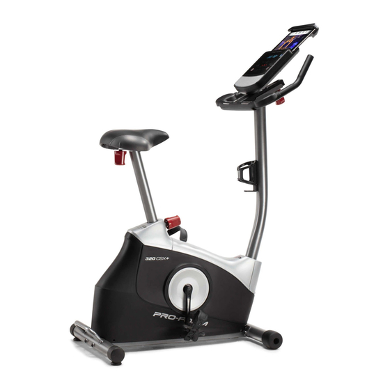
BEFORE YOU BEGIN Thank you for selecting the revolutionary PROFORM reading this manual, please see the front cover of this ® 320 CSX + exercise bike. Cycling is an effective manual. To help us assist you, note the product model exercise for increasing cardiovascular fitness, build- number and serial number before contacting us. -
Page 5: Part Identification Chart
PART IDENTIFICATION CHART Use the drawings below to identify the small parts needed for assembly. The number in parentheses below each drawing is the key number of the part, from the PART LIST near the end of this manual. The number following the key number is the quantity needed for assembly. -
Page 6: Assembly
ASSEMBLY • Assembly requires two persons. • In addition to the included tool(s), assembly requires the following tools: • Place all parts in a cleared area and remove the one Phillips screwdriver packing materials. Do not dispose of the packing materials until you finish all assembly steps. - Page 7 3. If there are shipping tubes (not shown) attached to the rear of the Frame (50), remove and discard the shipping screws and the shipping tubes. Next, set a sturdy piece of packing material under the rear of the Frame (50). Attach the Rear Stabilizer (44) to the Frame (50) with two M10 x 80mm Screws (46).
- Page 8 5. Have a second person set the Seat Carriage (15) on the Seat Post (18) and hold it in place. Identify the Seat Bracket (14), which is smaller than the Handlebar Bracket (not shown). Next, insert the Seat Bracket (14) into the Seat Carriage (15), and align the hole in the Seat Bracket with the hole (B) in the top of the Seat Post (18).
- Page 9 7. Locate the lower end of the wire tie (C) in the Upright (27). Tie the wire tie to the Main Wire (25). Then, pull the upper end of the wire tie until the Main Wire is routed through the Upright. Tip: To prevent the Main Wire (25) from falling into the Upright (27), secure the Main Wire with the wire tie (C).
- Page 10 9. Have a second person hold the Handlebar (4) near the Upright (27). Route the Main Wire (25) through the large slot (D) in the underside of the Handlebar (4) and through the large opening (E). Tip: Avoid pinching the Main Wire (25). Have the second person set the Handlebar (4) on the Upright (27) and hold it in place.
- Page 11 11. Tip: Avoid pinching the wires. Attach the Console (7) to the Handlebar (4) with four M4 x 12mm Screws (33); start all the Screws, and then tighten them. Avoid pinching the wires 12. Identify the Right Pedal (60). Using the included wrench, firmly tighten the Right Pedal clockwise into the Right Crank Arm (59).
-
Page 12: How To Use The Exercise Bike
HOW TO USE THE EXERCISE BIKE HOW TO PLUG IN THE POWER ADAPTER HOW TO ADJUST THE HEIGHT OF THE SEAT IMPORTANT: If the exercise bike has been exposed For effective exercise, the seat should be at the proper to cold temperatures, allow it to warm to room height. - Page 13 HOW TO ADJUST THE ANGLE OF THE HOW TO ADJUST THE PEDAL STRAPS HANDLEBAR To adjust the To adjust the pedal straps (F), angle of the first pull the ends handlebar, loosen of the straps off the handlebar the tabs (G) on knob (E), rotate the pedals.
- Page 14 CONSOLE DIAGRAM FEATURES OF THE CONSOLE a target pedaling speed as it guides you through an effective workout. The advanced console offers an array of features designed to make your workouts more effective and You can even listen to your favorite workout music or enjoyable.
- Page 15 HOW TO USE THE MANUAL MODE approximate number of calories you have burned. When calorie workouts are selected, the approxi- 1. Begin pedaling or press any button on the mate number of calories that remain to be burned console to turn on the console. in the workout.
- Page 16 Scan mode—The console also has a scan mode To pause the console, simply stop pedaling or that will display workout information in a repeating press the End button. When the console is paused, cycle. To turn on the scan mode, press the Scan the time will flash in the display.
- Page 17 When your pulse is detected, your heart rate will be If the pedals do not move for several minutes and shown in the display. For the most accurate heart the buttons are not pressed, the console will turn rate reading, hold the contacts for at least 15 off and the display will be reset.
- Page 18 HOW TO USE AN ONBOARD WORKOUT As you exercise, you will be prompted to keep your pedaling speed near the target speed for the 1. Begin pedaling or press any button on the current segment. When the words TOO SLO console to turn on the console.
- Page 19 Time Workouts—Each Time workout is divided THE OPTIONAL CHEST HEART RATE MONITOR into one-minute segments. Adjust the resistance level and your pedaling speed as desired during Whether your each segment of a Time workout. goal is to burn fat or to The workout will continue in this way until the last strengthen your segment ends.
- Page 20 HOW TO CONNECT YOUR TABLET TO THE 5. Disconnect your tablet from the console if CONSOLE desired. The console supports BLUETOOTH connections To disconnect your tablet from the console, first to tablets via the iFit–Smart Cardio Equipment app select the disconnect option in the iFit–Smart and to compatible heart rate monitors.
- Page 21 HOW TO CHANGE CONSOLE SETTINGS Total Distance—The letters MI or KM will appear in the display. The display will show the total 1. Select the settings mode. distance (in miles or kilometers) that the exercise bike has been pedaled. To select the settings mode, press the Settings button.
-
Page 22: Maintenance And Troubleshooting
MAINTENANCE AND TROUBLESHOOTING MAINTENANCE Next, remove the indicated M4 x 20mm Screw (2) and the Upright Cover (9). Then, use a standard screw- Regular maintenance is important for optimal driver to carefully remove the Shield Cover (26). performance and to reduce wear. Inspect and properly tighten all parts each time the exercise bike is used. - Page 23 HOW TO ADJUST THE DRIVE BELT Using an M10 socket wrench with an extension (not included), reach into the opening in the bottom of the If you can feel the pedals slip while you are pedaling, Right Shield (58) and tighten the M10 x 55mm Screw even while the resistance is adjusted to the highest (49) a few turns until the Drive Belt (not shown) is tight;...
-
Page 24: Exercise Guidelines
EXERCISE GUIDELINES Burning Fat—To burn fat effectively, you must exer- WARNING: cise at a low intensity level for a sustained period of Before beginning this time. During the first few minutes of exercise, your or any exercise program, consult your physi- body uses carbohydrate calories for energy. - Page 25 SUGGESTED STRETCHES The correct form for several basic stretches is shown at the right. Move slowly as you stretch; never bounce. 1. Toe Touch Stretch Stand with your knees bent slightly and slowly bend forward from your hips. Allow your back and shoulders to relax as you reach down toward your toes as far as possible.
-
Page 26: Part List
PART LIST Model No. PFEVEX72917.1 R0119A Key No. Qty. Description Key No. Qty. Description Handlebar Bracket Crank Screw M4 x 20mm Screw Left Crank Arm Lower Handlebar Cover Front Stabilizer Handlebar Left Shield Round Handlebar Cap Snap Ring Upper Handlebar Cover/Pulse Grip Bearing Console M4 x 10mm Screw... -
Page 27: Exploded Drawing
EXPLODED DRAWING Model No. PFEVEX72917.1 R0119A... -
Page 28: Ordering Replacement Parts
ORDERING REPLACEMENT PARTS To order replacement parts, please see the front cover of this manual. To help us assist you, be prepared to provide the following information when contacting us: • the model number and serial number of the product (see the front cover of this manual) •...