Table of Contents
Advertisement
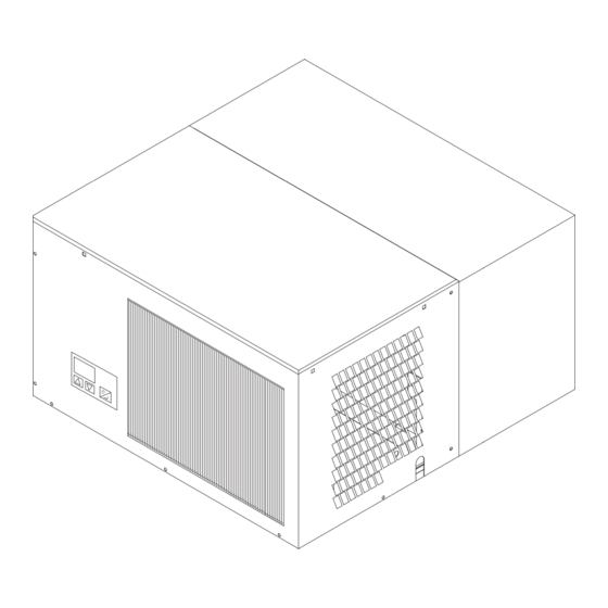
CT and FT ceiling-mounted
refrigeration units
Prior to beginning work on the refrigeration unit, please pay attention to the following:
Only a refrigeration specialist is permitted to carry out the
assembly, maintenance, and cleaning of the unit.
Technical changes are prohibited.
The guarantee is invalidated if these conditions are not kept to.
General notice (liability): the details of this technical documents serve for description. Consents regarding the availability of certain features or
regarding a certain purpose always require a special written agreement.
Page 1 GB
Assembly and
operation manual
6008521-01 GB
Work on the refrigeration unit is only permitted when the plug
is disconnected from the power supply. The unit must be
protected from reactivation using suitable warning signs.
Regulations VDE 0105 for work on electrical installations must
be observed.
Right reserved to make technical changes! Valid 10.14
GB
Advertisement
Table of Contents

Summary of Contents for Viessmann FT 0700
- Page 1 CT and FT ceiling-mounted refrigeration units Assembly and operation manual 6008521-01 GB Prior to beginning work on the refrigeration unit, please pay attention to the following: Work on the refrigeration unit is only permitted when the plug Only a refrigeration specialist is permitted to carry out the is disconnected from the power supply.
-
Page 2: Table Of Contents
Connecting a bus line Schematics of the refrigeration circulation Electrical circuit diagram for Condensation drainage CT 0900 to CT 2000, FT 0700 to FT 1200 Electrical circuit diagram for CT 3000 and FT 1500 Electrical power supply of the coldroom Faults... -
Page 3: Description
2006/42/EG. Deep-freezer refrigeration units The unit has been inspected at the factory for refrigerati- FT 0700, FT 1000, FT 1200, FT 1500 on circulation leakage and for function. The units are designed for refrigeration of rooms in which goods are kept at temperatures between -1°C and -25°C. -
Page 4: Transport
Do not install the unit in areas where danger of explosion Unpacking and handling exists. - Prior to and during unpacking, a visual check should be Do not install the unit in areas where excessive danger of made to determine if there has been any damage during fire exists. -
Page 5: Cleaning And Maintenance Of The Refrigeration Unit
Cleaning and maintenance of the refrigeration unit Installation of the refrigeration unit in a Viessmann coldroom Attention! Attention! Remove the plug from the power source during cleaning and maintenance, and ensure it cannot be Prior to assembly, the load capacity of the coldroom accidentally reinserted. - Page 6 Place the enclosed neoprene dowels M4 in the 8mm drill holes. Assemble the evaporation fan unit on the inside plating so that the exhaust opening is pointing in the right direction. Screw the evaporation fan unit on with the enclose M4 screws. Put the air jet in place and screw on tight on both sides with 3 screws each.
- Page 7 Seal the space between frame and cut-out with silicon. and adhere with armaflex tape. Mount the ceiling panel on the coldroom. Lift the machine section of the refrigeration unit up to the ceiling of the coldroom and position it on the cutout section such that the insulating wall of the unit is approx 10mm over the frame and the distance between frame and unit wall is about 50mm.
-
Page 8: Connections For Remote Control
Screw the air guide onto the ventilation box with three M6 screws such that the angled plate is pointing in the direction of the fan and is lying on the defrost water pan. Plug in the 4-pole plug of the electrical connection (located between evaporator and separating wall) in the socket in the evaporator ventilation unit, and lock in. -
Page 9: Connecting A Bus Line
Connecting a Bus Line If several units are being operated (max 31) in one coldroom, the remote control will be connected to the left socket (plug with pins), and the right-hand socket will be used to make the bus connection to the next unit. The other plug of the bus connector is plugged into the left Adress 1 Adress 2... -
Page 10: Connecting The Door Contact Switch
Connecting the door contact switch The evaporation fan should be switched off when the door 4-pin connector is open. We recommend installing a potential-free door on the unit from the coldroom contact switch. (Switching power 230VAC, min. 0.5A) The connection is made to the 4-pin socket on the suction 230VAC max. -
Page 11: Normal Operation
Operating the SD regulator Normal operation The current coldroom temperature is shown on the display. If one of the buttons is activated [ ] or [ ] the current temperature setting is shown. The right decimal point on the display lights up. If there is not further activation of the button within ten seconds, the room temperature is shown again. -
Page 12: Entering Temperature Setting
Entering parameters 7.2.1 Entering temperature setting If during operation the two buttons [ ] and [ ] are After entering the password, select Parameter P02 (Display activated simultaneously, the parameter function is will read SL.t), press Enter button and current temperature activated. -
Page 13: Selecting Humidity In The Coldroom
7.2.3 Selecting humidity in the coldroom After entering the password, select parameter P05 (Display will read „rF“), press Enter button, and the current type of operation of the evaporation fan will be shown. Using button [ ] the evaporator fan will begin constant operation (high relative humidity) display will show „HI“;... -
Page 14: Operator Access
7.2.6 Operator access The parameters P02 .. P23 can only be accessed if the password 5 is entered in parameter P01 or if the password for the operations parameters has been selected. The parameters shown in italics cannot be changed. Display reading of the selected parameter during entry of parameters Function Parameter... - Page 15 Fault Display Display Meaning Short-circuit in room sensor Room sensor broken Pressostat fault Coldroom temperature too high Coldroom door open Coldroom temperature too low Refrigeration capacity too low Evaporator sensor faulty Condenser sensor faulty Emergency Switch ON Fault in EEPROM Deactivating the refrigeration unit In case of longer periods of non-use or maintenance and cleaning, deactivate the refrigeration unit by pulling the...
-
Page 16: Types Of Operational Parameters
Types of operational parameters Parameter list Attention! The following parameters are important for the operation of the refrigeration unit. They may only be changed by specialists. It is therefore recommended that the password for the access to the parameters be kept secret. If the parameters are changed, the new ones should be entered in the column „Changed Values“. - Page 17 Recommended Changed Parameter Description Unit Range Normal Deep- values cooling freezer Running time, compressor, last cycle (hours) hours Running time, compressor, last cycle (minutes) minutes Running time, compressor, next to last cycle (hours) hours Running time, compressor, next to last cycle (min) minutes Running time, compressor, third-to-last cycle (hours) hours...
- Page 18 Recommended Changed Parameter Description Unit Range Normal Deep- values cooling freezer Current bus address Running time, defrosting break hours Running time, defrosting break minutes Calibration of room sensor -20..+20 Calibration of evaporator sensor -20..+20 Calibration of condenser sensor -20..+20 Regulator parameters (access if P01 = factory-password) Room sensor -50°...
-
Page 19: Description Of The Operational Types And Their Parameters
Description of the operational types and their - Defrosting is initiated at set times parameters P30 = x2 8.2.1 Defrosting Defrosting is initiated if the internal clock reaches one of the values entered in the parameters P12 – P23. If one of During the defrosting process, the display shows either the values in P12 –... -
Page 20: Condenser Fan (For Units With Rotational Speed Control)
8.2.2 Condenser Fan (for units with rotational speed control) 8.2.5 DCF Signal The condenser fan is equipped with a rotational speed Using the parameter P28, the DCF signal can be observed, control in some unit types. The liquefaction temperature is if the DCF Antenna is connected. -
Page 21: Drawings
Drawings 9.1 Schematics of the refrigeration circulation Compressor Pressure lead Hot gas U-pipe in defrost water pan Condenser High pressure switch Heat exchanger Drier Thermal expansion valve Evaporator 10 Suction pipe 11 Coldroom General notice (liability): the details of this technical documents serve for description. Consents regarding the availability of certain features or regarding a certain purpose always require a special written agreement. -
Page 22: Electrical Circuit Diagram For Ct 0900 To Ct 2000, Ft 0700 To Ft 1200
9.2 Electrical circuit diagram for CT 0900 to CT 2000, FT 0700 to FT 1200 General notice (liability): the details of this technical documents serve for description. Consents regarding the availability of certain features or regarding a certain purpose always require a special written agreement. -
Page 23: Electrical Circuit Diagram For Ct 3000 And Ft 1500
9.3 Electrical circuit diagram for CT 3000 and FT 1500 General notice (liability): the details of this technical documents serve for description. Consents regarding the availability of certain features or regarding a certain purpose always require a special written agreement. Page 23 GB Right reserved to make technical changes! -
Page 24: Faults
Faults If case of faults, the display will show a fault code. If the unit is not in refrigeration operation and not in defrosting operation, the fault report relay is not in operation. A fault report is possible using the potential-free contact. -
Page 25: Trouble-Shooting
10.3 Trouble-shooting Fault Cause Repair Plug is not inserted; Check plug and power supply: if no defect is visible, power supply not available. call refrigeration specialist. Activate emergency switch, see 10.2 Emergency Unit is not running. Regulator is defective. operation. Power supply is too low. - Page 26 Fault Cause Repair By pressing [ ] or [ ] the coldroom temperature will be shown again. The temperature alarm will be activated when the temperature setting is exceeded after the time-delay set in P44. If the temperature is Fault code E06. Coldroom temperature is too low.
-
Page 27: Scale Drawings
11. Scale Drawings Unit fits snugly to Unit fits snugly to ceiling element ceiling element General notice (liability): the details of this technical documents serve for description. Consents regarding the availability of certain features or regarding a certain purpose always require a special written agreement. Page 27 GB Right reserved to make technical changes! -
Page 28: Technical Data
12. Technical Data CT 0900 CT 1200 CT 1500 CT 2000 CT 3000 FT 0700 FT 1000 FT 1200 FT 1500 Coldroom temperature +20°C to -5°C -5°C to -25°C Power use [W] 1150 1450 1800 2600 1100 1400 +2°C to +40°C Allowable ambient temperature economical range +2°C to +25°C... - Page 29 Powerdiagramm FT-Units (ambient temperature +32°C) 2500W 2000W FT 1500 -18° FT 1200 1500W 1000W FT 0700 500W -25° -20° -15° -10° -5° General notice (liability): the details of this technical documents serve for description. Consents regarding the availability of certain features or regarding a certain purpose always require a special written agreement.
- Page 30 Viessmann Kühlsysteme GmbH Schleizer Straße 100 D-95030 Hof/Saale Telefon +49 9281 814-0 Telefax +49 9281 814-269 kuehlsysteme@viessmann.de www.viessmann.de/kuehlsysteme Your responsible refrigeration service: General notice (liability): the details of this technical documents serve for description. Consents regarding the availability of certain features or regarding a certain purpose always require a special written agreement.