Table of Contents
Advertisement
Applications
The FX-PCV1615/1626/1628/1630 programmable digital controllers are designed for controlling
Variable Air Volume (VAV) boxes. These FX-PCV Variable Air Volume Modular Assembly (VMA)
controllers feature combinations of an integral digital pressure sensor (DPT), a damper actuator,
and a 32-bit microprocessor. The FX-PCV1626 has an actuator but does not contain a DPT. The FX-
PCV1628 model has a DPT but does not contain an actuator. The controllers' small package size
facilitates quick field installation and efficient use of space without compromising high-tech control
performance. These FX-PCV controllers connect easily to the wired and wireless network sensors for
zone and discharge air temperature sensing.
Communications protocol
The FX-PC family controllers and network sensors communicate using the standard BACnet
protocol, based on the ANSI/ASHRAE 135-2008. The BACnet protocol is a standard for ANSI,
ASHRAE, and the International Standards Organization (ISO) for building controls.
FX-PCV controllers are BTL-listed as BACnet Application Specific Controllers (B-ASCs).
The Controller Configuration Tool (CCT) can be used to switch the Field Bus communications
protocol in supported FX-PC Controllers to be either the standard BACnet MS/TP or the N2 protocol.
All new controllers use either BACnet MS/TP as the default communications protocol, or BACnet/
IP. Switchable communications protocols in the MS/TP models provide a cost-effective upgrade and
modernization path for customers with existing N2 controllers.
The Modernization Guide for Legacy N2 Controllers (LIT-12012045) and the controller-specific
documentation provide installation and commissioning support and include tips for efficient
and safe replacement. Refer to the N2 Compatibility Options chapter of the Controller Tool
Help (LIT-12011147) for information about mapping N2 Objects in controllers with switchable
communications protocols.
The N2-capable FX-PC Controllers can be used as functional replacements for legacy N2 controllers.
The N2-capable FX-PC Controllers:
• have the I/O quantities and characteristics of the FX-PC family controllers
• must be programmed with CCT, which has programming capabilities that are similar (but not
identical) to HVACPro, GX9100, GPL, and other legacy tools
• support SA Bus devices
• support FX-WRZ wireless sensors from the controller using the FX-WRZ7860 receiver when
configured for BACnet MS/TP communication
The N2-capable FX-PC controllers:
• do not support Zone Bus (for example, TMZ sensors and M100 actuators)
• do not support passthrough in the commissioning mode
• do not support remote downloading or commissioning using BACnet routing
• do not support wireless connection to the N2 bus
Part No. 24-10143-357 Rev. H
2019-03-22
FX-PCV1615/1626/1628/1630 Programmable
VAV Box Controllers Installation
Instructions
*2410143357H*
(barcode for factory use only)
FX-PCV1615, FX-PCV1626, FX-PCV1628, FX-PCV1630
®
Advertisement
Table of Contents

Related Manuals for Johnson Controls FX-PCV1615


Summary of Contents for Johnson Controls FX-PCV1615
- Page 1 VAV Box Controllers Installation Instructions Applications The FX-PCV1615/1626/1628/1630 programmable digital controllers are designed for controlling Variable Air Volume (VAV) boxes. These FX-PCV Variable Air Volume Modular Assembly (VMA) controllers feature combinations of an integral digital pressure sensor (DPT), a damper actuator, and a 32-bit microprocessor.
-
Page 2: North American Emissions Compliance
• Do not drop the FX-PCV controller or subject it to physical shock. Parts included • One FX-PCV1615/1626/1628/1630 controller with removable SA bus and power terminal blocks. • One installation instructions sheet. • One self-drilling No. 10 x 25 mm (1 in.) screw. - Page 3 • Avoid mounting the FX-PCV on surfaces with excessive vibration. • When using the FX-PCV1615/1626/1628/1630 to replace an FX-PCV1610 or FX-PCV1620 controller, plug the unused open hole in the duct work from the original FX-PCV mounting if possible. Plug the hole using the sheet metal screw from the original installation (preferred option).
- Page 4 11. Push the Manual Override button, and turn the actuator coupling manually to ensure that the actuator can rotate from full-closed to full-open positions without binding. 12. Complete the mounting by rotating the damper to the full-open position. FX-PCV1615/1626/1628/1630 Programmable VAV Box Controllers Installation Instructions...
-
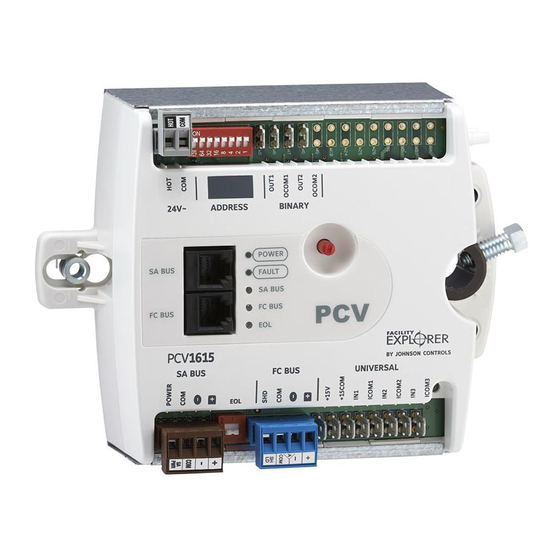
Page 5: Wiring Diagram
Le non-respect de cette directive risque d'endommager le caisson de l'unité à volume d'air variable (VAV) ou le réseau de conduites au démarrage de l'unité de traitement d'air. Wiring diagram Figure 2: PCV1615/1626/1628/1630 Controller wiring terminations and physical features FX-PCV1615/1626/1628/1630 Programmable VAV Box Controllers Installation Instructions... - Page 6 Table 1: FX-PCV1615/1626/1628/1630 Programmable VAV Box feature callout numbers and descriptions Callout Physical features: description and references 24 VAC, Class 2 Supply Power Terminal Block (see Supply power terminal block) Device Address DIP Switch Block Binary Outputs, 24 VAC Triacs (see Table 3) Configurable Outputs: Voltage Analog Output (0–10 VDC) and Binary Output (24 VAC...
- Page 7 Figure 3: FC bus terminal block wiring Note: The Shield terminal (SHLD) on the FC Bus terminal block is isolated and can be used to connect the cable shields on the bus (Figure 3). FX-PCV1615/1626/1628/1630 Programmable VAV Box Controllers Installation Instructions...
- Page 8 Bluetooth Commissioning Converter and the FX-ZFR Wireless Router. Note: Do not use the modular SA Bus port and the terminal block SA Bus simultaneously. Only use one of these connections at a time. FX-PCV1615/1626/1628/1630 Programmable VAV Box Controllers Installation Instructions...
- Page 9 Figure 6: 24 VAC supply power terminal block wiring Important: Exercise caution while rewiring the power plug when replacing an FX-PCV1610 or FX-PCV1620 controller withan FX-PCV1615/1626/1628/1630 controller. The supply power terminal on a new FX-PCV is a two-position terminal block (Figure 6). An FX-PCV1610 or FX- PCV1620 controller uses a three-position terminal block, and the center position is not used.
- Page 10 Also, activate the EOL switch if necessary. 4. Connect the FX-PCV controller to 24 VAC, Class 2 power. Note: If you are using the FX-PCV1615/1626/1628/1630 controller with the Wireless Field Bus System, refer to the WNC1800/FX-ZFR182x Pro Series Wireless Field Bus System Bulletin (LIT-12012378) or the FX-ZFR1800 Series Wireless Field Bus System Bulletin (LIT-12011660).
-
Page 11: Termination Diagrams
SA Buses. Termination diagrams A set of Johnson Controls termination diagrams provides details for wiring inputs and outputs to the controllers. See the figures in this section for the applicable termination diagrams. - Page 12 Table 2: Termination details Type of field Type of Termination diagrams device Input/ Output Voltage Input (Self-Powered) Temperature Sensor Dry Contact 0–10 VDC Output to Actuator (External Source) 0–10 VDC Output to Actuator (Internal Source) FX-PCV1615/1626/1628/1630 Programmable VAV Box Controllers Installation Instructions...
- Page 13 Note: Applies to CO4 and CO5. Analog Output (Voltage) Incremental Control to Actuator (Switch Low, Internally Sourced) Note: Applies to BO3 (for FX-PCV1630 only), BO1, and BO2. 24 VAC Binary Output (Switch Low, Internally Sourced) FX-PCV1615/1626/1628/1630 Programmable VAV Box Controllers Installation Instructions...
-
Page 14: Input And Output Wiring Guidelines Tables
Same as (Universal) INn. (3-wire) input devices connected (Inputs) Note: Use 3-wire cable for to the Universal INn terminals. devices that source power from the +15 V terminal. Provides 35 mA total current. FX-PCV1615/1626/1628/1630 Programmable VAV Box Controllers Installation Instructions... - Page 15 ICOMn terminals are isolated from FC BUS COM terminals only. BINARY OUTn Binary Output - 24 VAC Triac See Guideline C in Table 4. (Internal Power) (Outputs) Sources internal 24 VAC power (24~ HOT) FX-PCV1615/1626/1628/1630 Programmable VAV Box Controllers Installation Instructions...
- Page 16 40 mA minimum load current OCOMn Analog Output Signal Same as (Configurable) OUTn. Common: All Configurable Outputs defined as Analog Outputs share a common, which is isolated from all other commons except the Binary Input common. FX-PCV1615/1626/1628/1630 Programmable VAV Box Controllers Installation Instructions...
- Page 17 61 m (200 ft) twisted point. stranded copper 107 m wire (350 ft) twisted wire See Figure 8 to select wire See Figure 8 to size/gauge. determine cable length. Use stranded copper wire. Use twisted wire cable. FX-PCV1615/1626/1628/1630 Programmable VAV Box Controllers Installation Instructions...
-
Page 18: Communication Bus And Supply Power Table
Note: The + and - SA PWR 15 VDC Supply Power for wires are one twisted Devices on the SA Bus pair, and the COM and SA PWR wires are the second twisted pair. FX-PCV1615/1626/1628/1630 Programmable VAV Box Controllers Installation Instructions... - Page 19 The SA Bus and FC Bus wiring recommendations in this table are for MS/TP Bus communications at 38.4k baud. For more information, refer to the FX-PC Series Controllers MS/TP Communications Bus Technical Bulletin (LIT-12011670). FX-PCV1615/1626/1628/1630 Programmable VAV Box Controllers Installation Instructions...
-
Page 20: Setup And Adjustments
Note: Do not connect a wirelessly enabled FX-PC controller to a wired FC Bus. Refer to the FX-ZFR Series Wireless Field Bus System Technical Bulletin (LIT-12011660) for more information on device addresses in wireless applications. FX-PCV1615/1626/1628/1630 Programmable VAV Box Controllers Installation Instructions... -
Page 21: Setting The N2 Controller Address To Be Greater Than 127
N2-configured controllers support the full range of possible N2 device addresses provided by the N2 protocol standard (1-255). However, these controllers require special configuration for addresses above 127. Use the following instructions for controller addresses greater than 127. Notes: FX-PCV1615/1626/1628/1630 Programmable VAV Box Controllers Installation Instructions... -
Page 22: Setting The Eol Switch
EOL switch to OFF. Note: When the EOL switch is set to ON, the LED light on the face of the controller is illuminated. FX-PCV1615/1626/1628/1630 Programmable VAV Box Controllers Installation Instructions... -
Page 23: Repair Information
Possible Cause: 1. Transformer is shorted. 2. 24VAC powered sensor is not wired with the same polarity as the controller. 3. SA bus device is not wired with the same polarity as the controller. FX-PCV1615/1626/1628/1630 Programmable VAV Box Controllers Installation Instructions... - Page 24 0–10V output has an undesirable offset of up to 1 V and Common Reference is incorrect. Possible Cause: OCOM terminal is not connected. Correction: Connect OCOM terminal of the configurable output to the common of the connected end device. FX-PCV1615/1626/1628/1630 Programmable VAV Box Controllers Installation Instructions...
-
Page 25: Led Table
Off Steady = ETH2 is not connected Blinking = ETH2 connected and communicating Accessories Use Table 9 to order accessories. Table 9: FX-PCV1615/1626/1628/1630 Controller Accessories (Order Separately) Product code number Description FX-PCX Series Expansion Refer to the FX-PC Series Programmable Controllers and Related... - Page 26 Replacement Barbed Fitting for use on FX-PCV1615, FX-PCV1630, and FX-PCV1832 for Connecting Tubing, Bulk Pack of 10 F-1000-326 Flexible Tubing Extension with Barbed Fitting for FX-PCV1615, FX- PCV1630, and FX-PCV1832, 35.56 cm (14 in.) Length, Bulk Pack of 20 FX-PCVACT-701...
-
Page 27: Technical Specifications
Storage: -40°C to 70°C (-40°F to 158°F) Terminations Inputs/Outputs: 6.3 mm (1/4 in.) Spade Lugs FC Bus, SA Bus, and Supply Power: 4-Wire and 2-Wire Pluggable Screw Terminal Blocks SA Bus Modular Ports: RJ-12 6-Pin Modular Jacks FX-PCV1615/1626/1628/1630 Programmable VAV Box Controllers Installation Instructions... - Page 28 UL Listed, File E107041, CCN PAZX, UL 916, Energy Management Equipment; Suitable for use in other environmental air space (plenums) in accordance with Section 300.22(C) of the National Electric Code. FCC Compliant to CFR47, Part 15, Subpart B, Class A. FX-PCV1615/1626/1628/1630 Programmable VAV Box Controllers Installation Instructions...
-
Page 29: Points Of Single Contact
The performance specifications are nominal and conform to acceptable industry standard. For application at conditions beyond these specifications, consult the local Johnson Controls office. Johnson Controls shall not be liable for damages resulting from misapplication or misuse of its products. - Page 30 © 2019 Johnson Controls. All rights reserved. All specifications and other information shown were current as of document revision and are subject to change without notice. www.johnsoncontrols.com...