
Related Manuals for Honeywell IB2


Summary of Contents for Honeywell IB2
- Page 1 Montage-Anschluss-Anleitung IB2 BUS-Erweiterung Art.-Nr. 013930 P00184-10-002-05 Anerkennung Änderungen G115070 vorbehalten 2017-05-10...
-
Page 2: Table Of Contents
5.3 Richtlinien RS-485- und IB2-Bus ........ -
Page 3: Anwendung
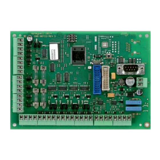
Die IB2 BUS-Erweiterung dient zum Ausbau einer MB-Secure Zentrale um zusätzliche BUS-2- oder RS-485-Stränge (umschaltbar) und eine RS-232-Schnittstelle. Die Verbindung zur MB-Secure erfolgt über den IB2 BUS, dabei kann das Modul sowohl im Zentralengehäuse als auch abgesetzt mit bis zu 2000 m Kabellänge betrieben werden. -
Page 4: Funktionsbeschreibung
Montage-Anschluss-Anleitung IB2 BUS-Erweiterung Funktionsbeschreibung Anschluss an die Zentrale Die IB2 BUS-Schnittstelle der IB2 BUS-Erweiterung wird an einem der 4 Controller-Anschlüsse Zentrale MB-Secure angeschlossen. Die Schnittstelle der Zentrale muss als RS-485/IB2-Schnitt- stelle konfiguriert werden. Bus-Ausgänge Die 4 Bus-Ausgänge sind über die Zentralenprogrammierung einzeln als BUS-2- oder RS-485- Schnittstelle konfigurierbar (RS-485 in Vorbereitung). -
Page 5: Montage
Gehäuse aus unserem Katalog. Bei Anlagen gemäß EN ist nur ein Gehäuse für MB-Secure Zentralen zulässig! (ZG20, ZG2, ZG3.1 oder ZG4). Zulässige Leitungslänge zwischen der Zentrale und der IB2 BUS-Erweiterung: max. 2000 m (siehe 5.3.2). Modul in das Gehäuse einbauen •... -
Page 6: Installationsrichtlinien
(Kapitel Leitungen) zu entnehmen. Schirm im Gehäuse jeweils an der Schirm-Anschlussleiste anschließen. Halten Sie die Schirm- anschlüsse möglichst kurz, um die Gefahr eines Kurzschlusses zu vermeiden. BUS-2 IB2 BUS / RS-485 +12 V DC +12 V DC A / Daten... -
Page 7: Richtlinien Rs-485- Und Ib2-Bus
Ggf. entsprechende Jumper entfernen (JP1 – JP4). 4x BUS-2 / RS-485 5.3.2 Leitungslängen Bei der IB2- bzw. RS-485-Installation sind unten stehende Leitungslängen unbedingt zu beachten. RS-485 / IB2 Teilnehmer max. 40 m RS-485 / IB2 Teilnehmer... -
Page 8: Anschlussplan
U_b4 - 12 V DC / 26 Ah (013950) Eingang oder U_ext, Ext.3 U_b5 Betriebsspannung - 12 V DC / 52 Ah (013960) ACHTUNG! Bei Montage der IB2 BUS-Erweiterung im abgesetzten Gehäuse muss zur Spannungsversorgung ein separates Netzteil eingesetzt werden. -
Page 9: Analog-Eingänge
Update mit "FFAST" durchführen. Anschließend DIP-Schalter 1 wieder auf "OFF" stellen. Reset-Taster drücken oder Betriebsspannung U_b5 kurzzeitig unterbrechen. Hinweis : Firmware-Update über den IB2 Bus ebenfalls möglich. Information zu den Firmwareversionen Bei Betrieb der IB2 Bus-Erweiterung an der Zentrale MB-Secure sind... -
Page 10: Technische Daten
Montage-Anschluss-Anleitung IB2 BUS-Erweiterung Technische Daten Betriebsnennspannung 12 V DC Betriebsspannungsbereich 10,5 V DC bis 15 V DC Ruhestromaufnahme bei U_b = 12 V DC max. 65 mA 4 Analog-Eingänge: - Betrieb als Meldergruppe (E1 löschbar): - Spannung 8 V DC, stabilisiert, kurzschlussfest... - Page 11 Mounting and Connection Instructions IB2 Bus Expander Item no. 013930 P00184-10-002-05 Subject to change approval G115070 without notice 2017-05-10...
- Page 12 5.3 Guidelines RS-485 and IB2 bus........
-
Page 13: Application
Mounting and Connection Instructions IB2 Bus Expander Application The IB2 BUS expander is intended for the extension of an MB-Secure control panel with additional BUS-2 or RS-485 lines (switchable) and an RS-232 interface. The connection to the MB-Secure is established via the IB2 BUS. The module can be operated both in the panel housing and remotely with a cable length of up to 2000 m. -
Page 14: Function Description
Function description Connection to panel MB-Secure The IB2 BUS interface of the IB2 BUS expander is connected to one of the 4 controller connections of the control panel MB-Secure. The interface of the control panel must be configured as an RS-485/IB2 interface. -
Page 15: Mounting
Mounting and Connection Instructions IB2 Bus Expander Mounting Guidelines Mounting on the metal housing base of the control panel or in a separate metal housing. The circuit board size corresponds with the existing I-BUS modules. Please refer to Chapter “Grounding and Shielding” in the Instructions for the Installer of the MB- Secure control panel. -
Page 16: Installation Guidelines
Mounting and Connection Instructions IB2 Bus Expander Installation guidelines Bus connection lines The BUS connecting cable must be a shielded, twisted pair line. Wires must correspond with the diagram below. The corresponding line cross-sections can be found in the installation instructions of the intruder alarm control panel (see "Lines"). -
Page 17: Guidelines Rs-485 And Ib2 Bus
Mounting and Connection Instructions IB2 Bus Expander Guidelines RS-485 and IB2 bus 5.3.1 Bus End of line resistors (EOL) With jumpers JP1 to JP4 the EOL resistors of the 4 RS-485 interfaces are activated/deactivated, with jumper JP5 the EOL resistor of the IB2 BUS interface is activated/deactivated. -
Page 18: Connection Diagram
- 12 V DC / 26 Ah (013950) U_b4 Out4 Input U_ext, Ext.3 U_b5 - 12 V DC / 52 Ah (013960) Operating voltage ATTENTION! A separate power supply is required, when the IB2 Bus Expander is mounted in a separate housing. -
Page 19: Analogue Inputs
Press "Reset" button or interrupt operating voltage U_b5 briefly. Note : Firmware update also possible via IB2 bus Information to firmware versions When installing the control panel MB-Secure in combination with the IB2 Bus Expander, following firmware versions are absolutely necessary: MB-Secure IB2 Bus Expander up to V04.7x... -
Page 20: Technical Data
Mounting and Connection Instructions IB2 Bus Expander Technical Data Rated operating voltage 12 V DC Operating voltage range 10.5 V DC to 15 V DC No-load current at UB=12 V DC max. 65 mA 4 Analogue inputs: - Operation as Detector group (In1 with clear function):...