
Related Manuals for Emerson Comfort Alert 543-0038-01


Summary of Contents for Emerson Comfort Alert 543-0038-01
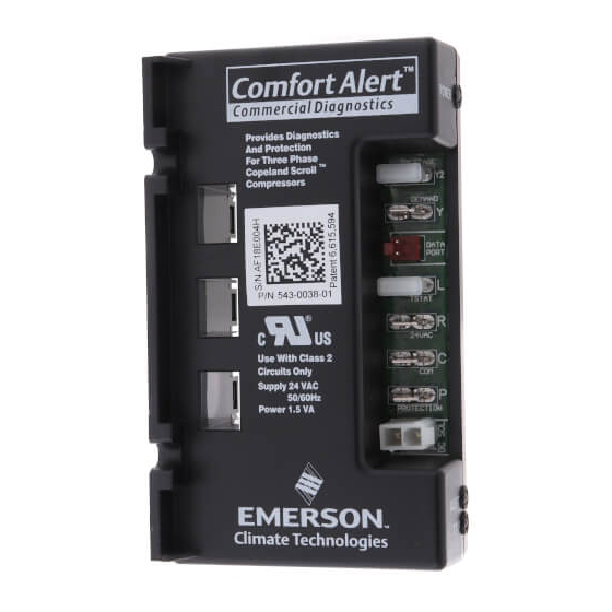
- Page 1 Comfort Alert ™ Commercial Diagnostics 543-0038-01, 543-0071-00, 543-0038-02, 943-0038-01, 943-0038-02 User’s Manual...
- Page 2 ™ Comfort Alert Diagnostics – Faster Service And Improved Accuracy The Comfort Alert diagnostics module is a breakthrough innovation for troubleshooting ™ and protecting three phase Copeland Scroll compressors. The module installs easily in the electrical box of the condensing unit near the compressor contactor. By monitoring and analyzing data from the Copeland Scroll compressor and the thermostat demand, the module can accurately detect the cause of electrical and system related failures and protect the compressor.
- Page 3 Dimensions A – 1.85 in (47 mm) D – 4.40 in (112mm) B – 2.44 in (62 mm) E – 2.44 in (62 mm) C – 1.46 in (37 mm) Figure 3 Figure 2 Model dimensions - Single Stage Model Dimensions - Two Stage Hazardous voltage inside air conditioning system.
- Page 4 24VAC Power Wiring The Comfort Alert module requires a constant nominal 24VAC power supply. The wiring to the module’s R and C terminals must be directly from the control transformer. The module cannot receive its power from another device that will interrupt the 24VAC power supply.
- Page 5 Two-Stage Solenoid COMFORT ALERT DIAGNOSTICS MODULE 543-0038-00 3 Phase 208-575VAC 50/60Hz HPCO LPCO Three Phase Copeland Scroll ™ Compressor Two-Stage Only Optional PROT Two-Stage Only DC SOL INDOOR THERMOSTAT Schematic Abbrevation Descriptions Note: Y2 and DC SOL are not applicable for models Compressor Contactor 543-0038-02 and 943-0038-02.
- Page 6 Two-Stage COMFORT ALERT Solenoid DIAGNOSTICS MODULE 543-0038-00 3 Phase 208-575VAC 50/60Hz HPCO LPCO Three Phase Copeland Scroll ™ Compressor 10 k Ohm Resistor Two-Stage Only Optional PROT Two-Stage Only DC SOL SYSTEM CONTROLLER I1, I2 = Controller Inputs O1, O2 = Controller Outputs Note: Y2 and DC SOL are not applicable for models R, C = Controller Power 543-0038-02 and 943-0038-02.
- Page 7 PROT Terminal The PROT terminal provides the compressor protection functionality for Comfort Alert. If a compressor damaging code is active, the PROT terminal interrupts the common leg of the compressor contactor coil. This terminal is rated for a maximum of 1 Amp (24 VA) and is only compatible with AC coils.
- Page 8 still active. The TRIP LED will again fl ash for the duration of the anti short cycle time, after the anti short timer expires, the Trip LED will illuminate and remain solid as long as the compressor power remains disconnected and demand is still present. If the red LED does not function as described, refer to Table 1 to verify the wiring.
- Page 9 Module locks out compressor when compressor damaging ALERT codes appear Lockout ALERT codes are noted in the Status LED Description During a compressor lock out, 24VAC power must be removed from module to manually reset Yellow “ALERT” A short circuit or over 1.
- Page 10 Yellow “ALERT” Missing Phase 1. Compressor fuse is open on one phase Flash Code 6 LOCKOUT 2. Broken wire or connector on one phase 3. Compressor motor winding is damaged 4. Utility supply has dropped one phase Yellow “ALERT” Reverse Phase 1.
- Page 11 NOTE: The correct Comfort Alert model must be used for the application (refer to the Product Specifi cation section on page 2). If the wrong model is installed, the ALERT Flash Codes for system faults will function incorrectly: the Comfort Alert module may indicate system faults that are not present or fail to indicate system faults that are present.
- Page 12 fi rst. During this period, Emerson Climate Technologies, Inc. will replace any defective diagnostic module without charge.