
Summary of Contents for Ferroli FCS-C Series
- Page 1 FCS-C VENTILCONVETTORE A CASSETTA “CASSETTE” FAN COIL MOD: 04-08-10-12-16-20 04-4T 10-4T 20-4T MANUALE DI INSTALLAZIONE INSTALLER’S MANUAL...
- Page 2 FERROLI S.p.A Dear Customer, Thank you for having purchased a FERROLI domestic air conditioner. It is the result of many years experience, particular research and has been made with top quality materials and higlly advanced technologies. The CE mark guaranteed thats the appliances meets European Machine Directive requirements regarding safety. The qualitative level is kept under constant surveillance.
-
Page 3: Table Of Contents
SOMMARIO Sommario DESCRIZIONE UNITA’ . . . . . . . . . . . . . . . . . . . . . . . . . . . . . . . . . . . . . . . . . . . . . . . . . . . . . . . . . . . . . . . . . 4 Direttive europee . -
Page 4: Descrizione Unita
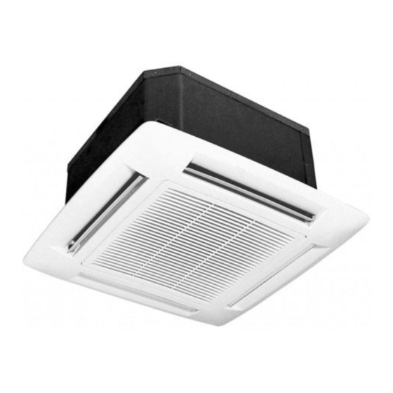
DESCRIZIONE UNITA’ DIRETTIVE EUROPEE L'azienda dichiara che la macchina in oggetto è conforme a quanto prescritto dalle seguenti direttive : • Direttiva macchine 2006/42/CE • Direttiva compatibilità elettromagnetica (EMC) 2004/108/CE • Direttiva bassa tensione (LVD) 2006/95/CE Ogni altra direttiva non espressamente citata è da considerarsi non applicabile. SCOPO DELLA MACCHINA Il ventilconvettore di tipo a cassette è... -
Page 5: Caratteristiche Generali
CARATTERISTICHE GENERALI ACCESSORI DISPONIBILI Gli accessori disponibili per questa categoria sono i seguenti: - Pannelli di Comando e Controllo E’ disponibile una serie di pannelli, per installazione remota a muro composta da tre diverse tipologie di comando: commutatore, termostato base e termostato evoluto. - Valvola a 3 vie (obbligatoria per il funzionamento a freddo) La valvola a tre vie è... -
Page 6: Dimensioni Per L'installazione Dei Modelli 04 - 08 - 10 E 04-4T E 10-4T
CARATTERISTICHE GENERALI DIMENSIONI PER L'INSTALLAZIONE DEI MODELLI 04 - 08 - 10 e 04-4T e 10-4T N .B .: Le quote riportate sono espresse in mm . MOD. 04-4T 10-4T PESO UNITA’ 15,0 16,5 16,5 16,5 19,0 PESO GRIGLIA ATTACCHI IDRAULICI 1- Ingresso batteria principale acqua fredda 2- Uscita batteria principale acqua fredda 3- Valvole per lo sfiato aria... -
Page 7: Dimensioni Per L'installazione Dei Modelli 12 - 16 - 20 E 20-4T
CARATTERISTICHE GENERALI DIMENSIONI PER L’INSTALLAZIONE DEI MODELLI 12 - 16 - 20 e 20-4T N .B .: Le quote riportate sono espresse in mm . MOD. 20-4T PESO UNITA’ 37,0 39,6 39,6 39,6 PESO GRIGLIA ATTACCHI IDRAULICI 1- Ingresso batteria principale acqua fredda 2- Uscita batteria principale acqua fredda 3- Valvole per lo sfiato aria 4- Ingresso batteria secondaria acqua calda... -
Page 8: Prescrizioni Di Sicurezza
CARATTERISTICHE GENERALI PRESCRIZIONI DI SICUREZZA La ditta costruttrice declina qualsiasi responsabilità per la mancata osservanza delle norme di sicu- rezza e di prevenzione di seguito descritte . Declina inoltre ogni responsabilità per danni causati da un uso improprio del ventilconvettore e/o da modifiche eseguite senza autorizzazione . L'installazione deve essere effettuata da personale esperto e abilitato. -
Page 9: Installazione
INSTALLAZIONE SCELTA DEL LUOGO DI INSTALLAZIONE Da evitare: · Posizione soggetta a raggi solari diretti. · Aree in prossimità di fonti di calore. · Luoghi umidi e posizioni dove l 'unità potrebbe venire a contatto con acqua (es:locali adibiti ad uso lavanderia). ·... -
Page 10: Attrezzature Necessarie Per L' Installazione
INSTALLAZIONE ATTREZZATURE NECESSARIE PER L’ INSTALLAZIONE Per l’installazione del ventilconvettore occorrono: · Tagliatubi · Giratubi per collegamento idraulico · Piegatubi · Cacciavite a croce e piatto · Metro · Trapano · Livella · Forbici · Occhiali e guanti protettivi · Spellafili PARTI ACCESSORIE NORMALMENTE IN COMMERCIO PER L’INSTALLAZIONE Per procedere con l’istallazione ci dobbiamo servire anche di:z ·... -
Page 11: Installazione Dell'unita
INSTALLAZIONE Fig. 1 INSTALLAZIONE DELL'UNITA' · Segnare la posizione di ogni sostegno, delle tubazioni di collegamento e di scarico della condensa,dei cavi elettrici di alimentazione e comandi (vedere dimensioni). La dima in cartone fornita a corredo puo essere di aiuto in tale operazione. ·... -
Page 12: Tubazioni E Scarico Condensa
INSTALLAZIONE Fig. 1 TUBAZIONI E SCARICO CONDENSA · Inserire il portagomma a corredo come da particolare in Fig.1. · Per la realizzazione della tubazione di scarico condensa è preferibile utilizza- re un tubo in PVC rigido di ø interno 25 mm. ·... -
Page 13: Installazione Della Valvola
INSTALLAZIONE INSTALLAZIONE DELLA VALVOLA ATTENZIONE: La valvola è necessaria non solo per controllare la temperatura ambiente, ma anche per bloccare il flusso dell'acqua refrigerata alla batteria nel caso di innalzamento anomalo del livello acqua condensa nel bacino . L'utilizzo di tale valvola si rende obbligatorio nel caso in cui l'unità venga utilizzata per raffrescamento . -
Page 14: Note Per L'attivazione Della Valvola
INSTALLAZIONE NOTE PER L’ATTIVAZIONE DELLA VALVOLA La valvola è controllabile mediante il commutatore o i due termostati forniti come accessorio secondo logiche diverse . Nel caso che un anomalo innalzamento del livello acqua di condensa nel bacino di raccolta (dovuto per esempio ad eventuale scarico difettoso,a guasto della pompa,a ventilazione non funzionante,etc.) provochi l ‘apertura del contatto del galleggiante 2LIV il circuito di controllo provvede sia a far funzionare la pompa di scarico condensa,sia contemporaneamente a far chiudere la valvola di regolazione, bloccando il flusso di... -
Page 15: Installazione Della Griglia
INSTALLAZIONE INSTALLAZIONE DELLA GRIGLIA Disimballare con cura l'assieme e controllare che non abbia subito Fig. 2 danni. Aprire la griglia operando sui nottolini 1-Fig 2 ed applicare l'as- sieme all'unità, agganciandola ai due supporti elastici di fissaggio 2-Fig 2. Eseguire i collegamenti fra il connettori presenti sula griglia e i relativi connettori in uscita dalla scheda elettronica Fissare la griglia alla cornice dell’unià... -
Page 16: Collegamenti Elettrici
COLLEGAMENTI ELETTRICI PROCEDURA DI COLLEGAMENTO DELL'UNITÀ IMPORTANTE: • L’unità deve essere installata conformemente alle regole impiantistiche nazionali. • Tutti i cavi di collegamento con l’unità, inclusi i relativi accessori, devono essere di tipo H05 VV-F, con isolante PVC in accordo alle EN 6033-2-40. •... - Page 17 COLLEGAMENTI ELETTRICI Di seguito sono riportati i collegamenti già presenti sulla macchina. LEGENDA SCHEMI ELETTRICI Connettori 1CF-1CM Connettore 1 Pompa-Galleggiante Comandi 3CF-32CM Connettore 3 Motore Ventilatore CMR-F Commutatore Remoto TAR-F Termostato Base Remoto Organi Interni TER-R Termostato Evoluto Remoto Pompa scarico condensa Motore Ventilatore Organi esterni Condensatore motore...
-
Page 18: Collegamenti Elettrici Comando Commutatore - Cmr-F
COLLEGAMENTI ELETTRICI 1 - COLLEGAMENTI ELETTRICI COMANDO COMMUTATORE - CMR-F Eseguire i collegamenti elettrici dell’unità con l’accessorio Comando Commutatore come da schema elettrico di seguito riportato. NOTA BENE Per il posizionamento dei Componenti Termostato di Consenso (TC) e Termostato di Consenso Ventilazione a Caldo (TC-F), fare riferimento alle relative "Note di Installazione". -
Page 19: Collegamenti Elettrici Comando Termostato Base - Tar-F
COLLEGAMENTI ELETTRICI 2 - COLLEGAMENTI ELETTRICI COMANDO TERMOSTATO BASE - TAR-F Eseguire i collegamenti elettrici dell’unità con l’accessorio Comando Termostato Base come da schema elettrico di seguito riportato. NOTA BENE Per il posizionamento dei Componenti Termostato di Consenso (TC) e la Sonda Batteria (SB), fare riferimento alle relative “Note di Installazione”. -
Page 20: 3- Collegamenti Elettrici Comando Termostato Evoluto - Ter-F
COLLEGAMENTI ELETTRICI 3- COLLEGAMENTI ELETTRICI COMANDO TERMOSTATO EVOLUTO - TER-F Eseguire i collegamenti elettrici dell’unità con l’accessorio Comando Termostato Evoluto come da schema elettrico di seguito riportato. NOTA BENE Per il posizionamento dei Componenti Termostato di Consenso (TC) e la Sonda Batteria (SB), fare riferimento alle relative “Note di Installazione”. -
Page 21: Opzioni Di Installazione
OPZIONI DI INSTALLAZIONE OPZIONI DI INSTALLAZIONE Le aperture laterali consentono la realizzazione separata di un condotto di aspirazione aria esterna di rinnovo (B) e di mandata aria trattata verso un locale attiguo (A). Aria esterna di rinnovo: · Togliere l'isolante esterno anticondensa, delimitato dalla fustellatura ed asportare i pannelli in lamiera micro- giuntati utilizzando un punteruolo,avendo cura di non danneggiare la batteria di scambio termico retrostante. -
Page 22: Note Di Installazione
OPZIONE DI INSTALLAZIONE NOTE DI INSTALLAZIONE Se si installa il comando “Commutatore” e per applicazioni in riscaldamento, è possibile subordinare il fun- zionamento del ventilatore al raggiungimento di una temperatura minima dell’acqua (42°C) in modo da evitare sgradevoli immissioni di aria fredda in ambiente. L’accessorio Termostato di Consenso (TC-F), da posizionare sulla tubazione ingresso acqua, consente infatti di monitorare la temperatura in ingresso batteria e può... -
Page 23: Manutenzione Ordinaria
MANUTENZIONE ORDINARIA CONTROLLO DEL VENTILCONVETTORE A CASSETTA Il controllo del ventilconvettore avviene a mezzo del pannello comandi, fissato a parete. Disponibile in tre versioni, commutatore, termostato base, termostato evoluto. COMMUTATORE 1: Controllo accensione/spegnimento: · Commutare la posizione del selettore superiore. Un led segnala il funzionamento del ventilconvettore (ad eccezione della versione CMR-F). -
Page 24: Norme Generali Per La Pulizia
MANUTENZIONE ORDINARIA NORME GENERALI PER LA PULIZIA ATTENZIONE: staccare la spina di alimentazione prima di effettuare operazioni di manutenzione o pulizia del ventilconvettore . Non versare acqua sul ventilconvettore, in quanto potrebbe causare danni meccanici o elettrici. Durante le operazioni di pulizia è assolutamente vietato usare: •... -
Page 25: Manutenzione Straordinaria
MANUTENZIONE ORDINARIA MANUTENZIONE STRAORDINARIA Manutenzione straordinaria: · Il quadro elettrico è facilmente accessibile rimuovendo il pannello di copertura. L’ispezione o la sostituzione dei componenti interni quali:motoventilatore, batteria di scambio termico,pompa scarico condensa,microgalleggiante di sicurezza richiedono la rimozione della bacinella di scarico condensa Rimozione bacinella scarico condensa: ·... - Page 27 TABLE OF CONTENTS INTRODUCTION . . . . . . . . . . . . . . . . . . . . . . . . . . . . . . . . . . . . . . . . . . . . . . . . . . . . . . . . . . . . . . . . . . . . . 28 Direttive europee .
-
Page 28: Introduction
INTRODUCTION DIRETTIVE EUROPEE The company hereby declares that the machine in question complies with the matters prescribed by the fol- lowing Directives: • Machinery directive 2006/42/CE; • Low voltage directive 73/23 EEC and modification 2006/95/CE; • Electromagnetic compatibility directive EMC 2004/108/CE All other regulations not specifically mentioned shall be deemed unenforceable. -
Page 29: General Specifications
GENERAL SPECIFICATIONS AVAILABLE ACCESSORIES The following accessories are available for this category: - Control and Monitoring Panels A set of panels is available for remote wall installation formed by three different types of control: commutator, basic thermostat and evolved thermostat. - 3-way valve (obligatory for operation in the cooling mode) The three-way valve is not only required to control the ambient temperature, but also to block the flow of chilled water to the coil if the level of condensed water in the tray should rise in an abnormal way. -
Page 30: Dimensions For Installing Models 04 - 08 - 10 And 04-4T And 10-4T
GENERAL SPECIFICATIONS DIMENSIONS FOR INSTALLING MODELS 04 - 08 - 10 and 04-4T and 10-4T NOTE: The dimensions are given in mm . MOD. 04-4T 10-4T unit weight 15,0 16,5 16,5 16,5 19,0 Grille weight HYDRAULIC CONNECTIONS 1-Water cold outlet 2-Water cold inlet 3-Air venting valve 4-Water heat outlet... -
Page 31: Dimensions For Installing Models 12 - 16 - 20 E 20-4T
GENERAL SPECIFICATIONS DIMENSIONS FOR INSTALLING MODELS 12 - 16 - 20 e 20-4T NOTE: The dimensions are given in mm . MOD. 20-4T unit weight 37,0 39,6 39,6 39,6 Grille weight HYDRAULIC CONNECTIONS 1-Water cold outlet 2-Water cold inlet 3-Air venting valve 4-Water heat outlet 5-Water heat inlet 6-to drain condensation (Æ25mm) -
Page 32: Safety Regulations
GENERAL SPECIFICATIONS SAFETY REGULATIONS The manufacturer declines all liability for failure to comply with the safety regulations and recommen- dations described below . The manufacturer also declines all liability for damage caused by improper use of the convector fan and/or by modifications made without authorization . The convector fan must be installed by expert, authorized personnel. -
Page 33: Installation
INSTALLATION CHOICE OF THE INSTALLATION SITE Positions to avoid: · Places in direct sunlight. · Positions near heat sources. · Damp places and positions where the unit could come into contact with water (e.g.: washrooms). · Places where shelves or furniture could prevent the air from circulating correctly. What to do: ·... -
Page 34: Tools Required For Installation
INSTALLATION TOOLS REQUIRED FOR INSTALLATION The following tools are required in order to install the · Wire stripper convector fan: · Pipe cutters · Pipe wrench for the wet connections · Pipe benders · Flat tip and cross-headed screwdrivers · Measuring tape ·... -
Page 35: How To Install The Appliance
INSTALLATION Fig. 1 HOW TO INSTALL THE APPLIANCE · Mark the position of each support, the connecting pipes and discharge of the condensate, of the electrical cables and power commands (see dimensions). The cardboard template can be supplied with help in this operation. -
Page 36: Pipes And Draining Off Condensation
INSTALLATION Fig. 1 PIPES AND DRAINING OFF CONDENSATION · Insert the supplied hose nipple as shown in Fig.1. · It is preferable to use a rigid PVC pipe with a 25 mm internal ø to drain off the condensation. · To ensure that the condensation flows away regularly, the drain pipe must slant 1% downwards without throttles or sections slanting upwards. -
Page 37: Valve Installation
INSTALLATION VALVE INSTALLATION WARNING: The valve is required not just to monitor the ambient temperature but also to shut off the chilled water that flows to the bank if the level of condensation in the tray becomes too high . It is obli- gatory to use this valve if the appliance is used for cooling purposes . -
Page 38: Notes About Valve Activation
INSTALLATION NOTES ABOUT VALVE ACTIVATION The appliance includes a condensation drain pump as part of the standard supply . Using a thermal contact sensor (TC), this pump always operates when the appliance is filled with cold water, thus in the cooling phase . The pump remains stationary when the temperature of the water entering the bank exceeds 25 °C and no condensation is formed. -
Page 39: Grille Installation
INSTALLATION GRILLE INSTALLATION Fig. 2 Carefully unpack the grille and make sure that it has not been damaged in any way. Open the grille by means of the pawls and fit it to the unit by hooking it on to the two flexible fastening supports 2-Fig 2. Connect the wire between the grill and the units Fix the grille to the frame of the unit with the 4 supplied screws. -
Page 40: Eletrical Connections
ELETRICAL CONNECTIONS PROCEDURE FOR CONNECTING THE UNIT IMPORTANT: • The unit must be installed in accordance with national wiring rules. • All cables with the unit, including accessories, must be type H05 VV-F, with PVC insulation according to EN 6033-2-40. •... - Page 41 ELETRICAL CONNECTIONS Here are the links that you already have. KEY TO ELECTRICAL WIRING connectors 1CF-1CM Pump Connector Float commands 3CF-32CM Fan Motor Connector 3 CMR-F Remote Switch TAR-F Remote Thermostat Base Internal Organs TER-R Remote Thermostat Evolved drain pump Fan Motor external bodies motor capacitor...
-
Page 42: Electrical Connections Of The Commutator Control - Cmr-F
ELETRICAL CONNECTIONS 1 - ELECTRICAL CONNECTIONS OF THE COMMUTATOR CONTROL - CMR-F Make the electric connections of the unit with Commutator Control accessory as shown in the following wiring diagrams. NOTE For positioning of the components thermostat Consensus (TC) and thermostat Ventilation Hot Consensus (TC- F), please refer to the “Installation Notes”. -
Page 43: 2-Electrical Connections Of The Basic Thermostat Control - Tar-F
ELETRICAL CONNECTIONS 2-ELECTRICAL CONNECTIONS OF THE BASIC THERMOSTAT CONTROL - TAR-F Make the electric connections of the unit with Basic Thermostat Control accessory as shown in the following wiring diagrams. NOTE For positioning of the components thermostat Consensus (TC) and thermostat Ventilation Hot Consensus (TC- F), please refer to the “Installation Notes”. -
Page 44: 3-Electrical Connections Of The Evolved Thermostat Control - Ter-F
ELETRICAL CONNECTIONS 3-ELECTRICAL CONNECTIONS OF THE EVOLVED THERMOSTAT CONTROL - TER-F Make the electric connections of the unit with Evolved Thermostat Control accessory as shown in the fol- lowing wiring diagrams. NOTE For positioning of the components thermostat Consensus (TC) and thermostat Ventilation Hot Consensus (TC- F), please refer to the “Installation Notes”. -
Page 45: Options Installation
OPTIONS INSTALLATION INSTALLATION OPTIONS The side openings allow a separate outdoor air change intake duct (B) and a delivery duct to convey treated air towards an adjacent room (A) to be made. Outdoor air change: · Remove the outer condensation-proof insulation delimited by the die-cut and take out the micro-jointed sheet metal panels using a punch. -
Page 46: Installation Notes
OPTIONS INSTALLATION INSTALLATION NOTES If the “Commutator” control is installed and for applications used in the heating mode, fan operation may be made to depend on a minimum water temperature being reached (42°C), this to prevent unpleasantly cold air from being blown into the room. The Enabling Thermostat accessory (TC-F), which should be installed on the water inlet pipe, allows the coil inlet temperature to be monitored and can be installed regardless of whether the three-way valve is installed. -
Page 47: Routine Manitenance
ROUTINE MAINTENANCE HOW TO OPERATE THE CASSETTE CONVECTOR FAN The convector fan is operated by means of a control panel fixed to the wall. Three versions are available, commutator, basic thermostat, advanced thermostat. COMMUTATOR 1: How to turn the appliance on/off: ·... -
Page 48: General Recommendations For Cleaning
ROUTINE MAINTENANCE GENERAL RECOMMENDATIONS FOR CLEANING WARNING: remove the power plug from the electricity main before servicing or cleaning the convector fan . Never pour water on to the convector fan. It could damage the mechanical or electrical parts. When the convector fan is cleaned, it is absolutely forbidden to use: ·... -
Page 49: Extraordinary Maintenance
ROUTINE MAINTENANCE EXTRAORDINARY MAINTENANCE Extraordinary maintenance: · The electric panel can be easily accessed by removing the cover. The condensation tray must be removed in order to inspect or replace the internal components, such as: fan, heat exchange bank, condensation drain pump and safety micro-float. - Page 50 La ditta costruttrice declina ogni responsabilità per le inesattezze contenute nel presente, se dovute ad errori di stampa o di trascrizioni. The manufacturer declines all responsibility for any inaccuracies in this manual due to printing or typing errors.
- Page 51 C e r t i f i c a t o d i g a r a n z i a C e r t i f i c a t o d i g a r a n z i a La presente garanzia convenzionale è...
- Page 52 Ferroli spa ¬ 37047 San Bonifacio (Verona) Italy ¬ Via Ritonda 78/A tel. +39.045.6139411 ¬ fax +39.045.6100933 ¬ www.ferroli.it...