Table of Contents
Advertisement
Quick Links
Advertisement
Table of Contents
Troubleshooting

Related Manuals for Bausch & Lomb STELLARIS PC

Summary of Contents for Bausch & Lomb STELLARIS PC
- Page 1 Operator’s Manual...
- Page 2 © Bausch & Lomb Incorporated. No part of this publication may be copied, photocopied, reproduced, translated, or reduced to any electronic medium or machine readable form, in whole or in part, without the prior written consent of Bausch & Lomb Incorporated, Rochester, NY 14609 USA. ™/® denote trademarks of Bausch & Lomb Incorporated. All other products/brands are trademarks of their respective owners. Manufacturing site: Bausch &...
-
Page 3: Indications For Use
Preface Indications for Use The Bausch + Lomb Stellaris® PC Vision Enhancement System device is intended for the emulsification and removal of cataracts, anterior and posterior segment vitrectomy. The system is designed for use in both anterior and posterior segment surgeries. It provides capabilities for phacofragmentation (coaxial or bimanual), irrigation/ aspiration, bipolar diathermy, vitrectomy, viscous fluid injection/removal and air/fluid exchange operations. - Page 4 Preface Power Outputs COAG 7.5 W 35 W 100 Ω 900 Ω 1 MHz 28.5 kHz Training Following system installation at a surgical facility, Bausch + Lomb personnel will provide on-site training to users who will operate the system. The training includes system startup, accessories and connections, priming and settings adjustment consistent with the instructions provided in this user manual.
- Page 5 Preface DANGER: Calls attention to an operating procedure, practice, or condition, which if disregarded or incorrectly performed, could result in imminent explosion hazard and risk of death or serious injury. WARNING: Calls attention to an operating procedure, practice, or condition, which if disregarded or incorrectly performed, could result in serious and/or permanent injury to personnel and/or patients.
- Page 6 Preface Direct Current Alternating Current Equipotential Foot Control Ground Remote Control Reception Indicator (Foot Control On/ TruLink ® Battery Customer Support Network Access) Dispose of Properly Battery Condition Indicator Serial Number Manufacturer Authorised Representative Date of Manufacture in the European Community Non Ionizing Caution: Consult Electromagnetic...
- Page 7 Preface Posterior Functions Fluid/Air Exchange EtO gas sterilized Illumination Gamma Irradiation Sterilized Do Not Reuse Viscous Fluid Control Do Not Re-Sterilize 21 CFR 801.109 (b) Caution: Federal (USA) law restricts this device to Do Not Use If Damaged sale by or on the order of a physician Member Green Dot Scheme Transport Symbol.
- Page 8 Preface Always wear eye protection or face mask when installing or removing the lamp Warning: Hot surface Electrostatic-sensitive device Never touch the silica glass bulb of the lamp with bare hands Xenon Xenon-Mercury Preface-6 Operator’s Manual 110017276EN Rev. B...
-
Page 9: Table Of Contents
Contents Getting Started 2.1. Components Shipped with the System ..................... 1-2 2.2. Connections and Setup ..........................1-2 2.3. System Description ..........................1-5 2.4. Setting Up Your System ........................... 1-6 2.5. Starting a New Procedure ........................1-15 2.6. Using Your System in Surgery ....................... 1-21 2.7. -
Page 10: Table Of Contents
Detailed Reference 5.1. Advanced Vacuum System Fluidics ......................4-1 5.2. Posterior Functions ..........................4-5 5.3. Anterior Functions ..........................4-29 5.4. Coagulation Function (Posterior & Anterior Modes) ................4-46 5.5. Combined Domain ..........................4-50 Cleaning and Sterilization Requirements 6.1. Routine Cleaning ............................. 5-1 6.2. -
Page 11: Getting Started
1 Getting Started Getting Started This chapter is for people who have used this type of ophthalmic vision enhancement system before and want to use the system without reading large portions of the manual. It also provides information on setting up your Stellaris® PC Vision Enhancement System and making the necessary connections. -
Page 12: Components Shipped With The System
1 Getting Started WARNING: To avoid risk of electric shock, this equipment must only be connected to a supply mains with protective earth. Note: Preventative scheduled maintenance is recommended once a year to insure that the Stellaris® PC Vision Enhancement System meets it optimum performance, reliability and safety standards set by the manufacturer. - Page 13 1 Getting Started Note: The out-of-factory Wireless System Setup is Disabled. Performing a software upgrade will also reset the Wireless System Setup to Disabled. To setup wireless operation, see Wireless Foot Control Operations System Setup on page 1-46 . The Stellaris® PC Vision Enhancement System is pre-configured at the factory to minimize setup and installation requirements.
- Page 14 1 Getting Started Foot Control The Foot Control can use either wired or wireless communication. The first time the Stellaris® PC Vision Enhancement System is used, you must use the wired connection to establish communication between the Foot Control and the Stellaris® PC Vision Enhancement System . For wired communication, connect the Foot Control backup cable from the back of the Foot Control to the lower rear of the Stellaris® PC Vision Enhancement System .
-
Page 15: System Description
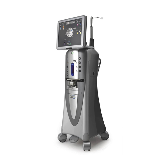
1 Getting Started Figure 1.2. Back bottom of system. Note: The system requires filtered medical grade air or medical grade nitrogen, at 72.5 to 100 psig (500 kPa to 690 kPa or 5.0 to 6.9 bar) and a flow rate of 2.25 SCFM (63.7 SLPM). 1.3. System Description The Stellaris® PC Vision Enhancement System has a modular design which enables it to be easily upgraded to take advantage of advances in technology. - Page 16 1 Getting Started Figure 1.3. Stellaris® PC Vision Enhancement System Your Stellaris® PC Vision Enhancement System was designed to be easily upgraded to take advantage of future technology evolution. It includes an 19 inch, 5:4 aspect ratio color touch screen display which is the primary interface between you and your system.
-
Page 17: Setting Up Your System
1 Getting Started combined surgery. The port near the IV Pole on the back of the system provides air for Pressurized Infusion (PI) in anterior surgery. The system can be set for either gravity infusion or infusion using pressurized air (AFI and PI, respectively) through the Infusion Tab of the or through the programming interface (see Chapter 3 ). - Page 18 1 Getting Started Before the first use of the Stellaris® PC Vision Enhancement System , connect the Foot Control to the system with the Foot Control backup cable provided with the system. The following pages contain an overview for setup and use of your Stellaris® PC Vision Enhancement System in a typical cataract surgery.
- Page 19 1 Getting Started Figure 1.4. Back bottom of system. 1. Main Power Switch. Note: The system requires filtered medical grade air or medical grade nitrogen, at 72.5 to 100 psig (500 to 690 kPa or 5.0 to 6.9 bar) and a flow rate of 2.25 SCFM (63.7 SLPM). Press the power button on the front of the system, and wait for the screen to come on and the animation to finish.
- Page 20 1 Getting Started Note: The out–of- factory Wireless System Setup is “Disabled”. Software upgrade will also reset the Wireless System Setup to “Disabled”. See System Setup Instructions on page 1-46 to configure Foot Control to wireless operation. If you are going to use the Foot Control in wireless mode, ensure the Foot Control battery is charged, then hold down any button on the Foot Control until the green ready light comes on, indicating that communication has been initiated.
- Page 21 1 Getting Started Once the software has finished loading, the will appear as shown below. Select Procedure screen Figure 1.6. Select Procedure Screen . (as shown in Figure 1.7 on page 1-12 ) will appear when you select any type of procedure Select Surgeon Screen from the Select Procedure Screen...
- Page 22 1 Getting Started Figure 1.7. Select Surgeon Screen . Select Surgeon Selecting Go To Surgery option will advance the system to the , using the system’s default Setup Screen parameters. Touch the name of a surgeon on the list to highlight it. Then select Confirm to load the parameters for that surgeon and advance to the Setup Screen Note:...
-
Page 23: Setup Screen
1 Getting Started Setup Screen allows you to set certain procedure parameters, and prepare the system for surgical procedures. Setup Screen The Open Pack/Insert Cassette option will be highlighted when you initially see this screen. If desired, select Select Room (Anterior Only) and choose the case number, number of operating rooms being used by the surgeon, and the particular operating room to be used. - Page 24 1 Getting Started Figure 1.9. Posterior Domain Case Menu Screen . 1-14 Operator’s Manual 110017276EN Rev. B...
- Page 25 1 Getting Started Figure 1.10. Combined Domain Case Menu Screen . Advance to the open pack step by selecting Open Pack Insert Cassette (Anterior Domain) or Insert Cassette (Posterior or Combined Domain) from the clock menu. 110017276EN Rev. B Operator’s Manual 1-15...
-
Page 26: Starting A New Procedure
1 Getting Started 1.5. Starting a New Procedure The Stellaris® PC Vision Enhancement System is user-friendly, and will highlight whichever step is next in a typical procedure. The steps shown on the display screen will vary slightly depending on which optional features are installed on your machine. - Page 27 1 Getting Started Figure 1.11. Schematic diagram of sterile draping. 1. Adhere screen drape on the top of the screen panel. 2. Screen drape. 3. Anterior Remote control drape. 4. Mayo Tray drape. 2. Setup Fluid Collection System Note: Ensure sufficient volume of irrigation solution is available for the procedure. The level should be monitored during the procedure.
- Page 28 1 Getting Started 3. Connect the proper accessories to the system for an Anterior, Posterior, or Combined procedure. Note: If you are using a vented Air Forced Infusion (AFI) pack, make sure to connect the Fluid/Air Exchange filter to the F/AX port on the front of the machine. Detailed setup instructions for each configuration are provided in Chapter 4 .
- Page 29 1 Getting Started WARNING: The animations illustrate the steps but do not represent sterile technique. 4. Prime and Tune Note: The system will not provide feedback as to whether or not fluid is present during priming. Inspect tubing and confirm that it is filled with fluid and free of bubbles after each Prime and Tune.
- Page 30 1 Getting Started For Combined Domain: • Select the Easy Prime button from the to fill the left and right tubing with Prime and Tune screen BSS solution, and then perform a test of the pneumatic cutter. During this process, the gravity feed infusion I/V pole will raise to 100 cm or lower if maximum ceiling height is set lower than 100 cm for the anterior.
- Page 31 1 Getting Started “Prime and Tune” • • Pressing the “Enter” button of the remote control activates the selected function as indicated by the arrow. • Once Prime and Tune is initiated by any of these options, a Cancel button will appear. Selecting the Cancel button will immediately stop the priming and tuning process.
- Page 32 1 Getting Started Figure 1.12. Prime and Tune Screen . This is an example of a posterior domain screen. 5. Advance to Surgery Phase WARNING: Inadvertent activation of functions that are intended for priming or tuning handpieces while the handpiece is in the eye can create a hazardous situation that could result in patient injury. Once the system has been successfully primed and tuned, it will automatically move to the main surgical screen.
-
Page 33: Using Your System In Surgery
1 Getting Started 1.6. Using Your System in Surgery Default parameters and settings are saved in the surgeon preference file, but can be modified during a procedure using the on-screen controls and surgical settings pop-up screens (see page 2-7 ). Your system will display the appropriate surgical screen for the current surgical mode. The interface is visibly different depending on the current operational mode. - Page 34 1 Getting Started Figure 1.14. Anterior Surgical Screen 1-24 Operator’s Manual 110017276EN Rev. B...
-
Page 35: Concluding A Surgical Procedure
1 Getting Started Figure 1.15. Combined Surgical Screen . 1.7. Concluding a Surgical Procedure Select End from the clock menu. Confirm that you are ready to end the case and eject the cassette, and you will be reminded to close the clamps on the administration tube set. A similar End function is accessible from the Setup Screen WARNING: Make sure to close the Irrigation Clamp on the Administration Tube Set before pressing End... - Page 36 1 Getting Started Figure 1.16. Anterior End of Case Screen . 1-26 Operator’s Manual 110017276EN Rev. B...
- Page 37 1 Getting Started Figure 1.17. Posterior End of Case Screen . 110017276EN Rev. B Operator’s Manual 1-27...
- Page 38 1 Getting Started Figure 1.18. Combined End of Case Screen . Remove the fluidics cassette immediately. Remove all disposables from the system. Select Show Me Steps Remove Disposables to see a list of which disposables need to be removed, and animations of how to remove each of them. Select Next Patient to return to the and prepare the machine for the next procedure, or select Shut Setup Screen...
-
Page 39: Shutting Down The System
1 Getting Started 1.8. Shutting Down the System CAUTION: Never turn the power switch off or disconnect the power without proper system shutdown. Equipment damage can occur. From the Screen, select Shut Down System. Select Yes to confirm shut down, or No to go back to System End . -
Page 40: Moving Your System To Another Location
1 Getting Started 1.10. Moving Your System to Another Location WARNING: Do not transport or move your system from room to room or up an inclination unless you have followed the steps below. This unit is designed to provide mobility within the environment of the operating room. Care must be taken as to avoid sloped floors greater than 5 degrees angle during use. -
Page 41: System Components
1 Getting Started 1.11. System Components The Stellaris® PC Vision Enhancement System has an advanced modular design with independent modules concealed in a uniquely designed exterior housing. The top level of the system is the user interface screen and computer unit. The surgical modules are concealed inside the main housing and strategically positioned to provide optimum user interaction and surgical functions. - Page 42 1 Getting Started User Interface Screen is the way the user communicates with the system. See Chapter 2 for basic user User Interface Screen interface controls. Technical specifications can be found in Chapter 8 . A typical interface setup screen is shown below.
- Page 43 1 Getting Started System Console Figure 1.20. Front of Stellaris PC system. 1. IV Pole. 2. Pneumatic Actuation Port. 3. Posterior Handpiece Connectors. 4. Drawer. 5. One-Touch Wheel Locking. 6. User Interface screen. 7. System Switch “On/Off”. 8. Handpiece Connectors. 9. Fluidic Module. 10. System Tray. This is the main unit, which contains the connections for all handpieces, Mayo tray, Ethernet connection and system housing.
- Page 44 CAUTION: To prevent loss of data, save data before the system shuts down. Figure 1.21. Stellaris PC System Rear View. 1. USB Port Access. 2. IV Pole Control Buttons. 3. Cord Wrap Hooks. 4. Foot Control Hook. 5. Air Pressure Output connector. The front of the system (see Figure 1.22 on page 1-35 ) contains multiple ports for connecting system accessories.
- Page 45 1 Getting Started There are 4 ports down the right side of the system for connecting specific system accessories. The first port (6 in figure below) is for Viscous Fluid Injection & Aspiration. The second port (7 in figure below) is for air forced infusion and Fluid/Air Exchange. The third port (8 in figure below) is for lamp 2 and provides illumination.
- Page 46 1 Getting Started Coagulation The third port on the left side of the system is for a coagulation handpiece which provides coagulation power in either Fixed or Linear modes. See page 4-46 for details of use and page 8-13 for technical specifications. The front of the system contains a total of ten ports for connecting system accessories.
- Page 47 1 Getting Started WARNING: This system is to be used in either air pressured infusion mode or IV Pole mode but never both together as high intraocular pressures may result. CAUTION: Do not manually force the IV Pole or use the IV Pole as a handle. The Stellaris® PC Vision Enhancement System IV Pole is an integral part of the system console.
- Page 48 1 Getting Started Figure 1.23. Remote Control functions. 1. Low Battery Light. 2. Transmitting Signal Light. 3. Next Phase. 4. Bottle Height. 5. Phaco/Vitrectomy or Coagulation. 6. Up and Down. 7. Flow. 8. Vacuum. 9. Previous Phase. 10. Enter. 11. Reserved for Future Use. In the anterior domain, the remote control can be used to activate functions in the “Prime and Tune” window of the setup screen.
- Page 49 1 Getting Started TruLink® Customer Support Network Remote Access (optional) The TruLink ® Customer Support Network feature improves system reliability by supporting remote diagnostics and performance analysis. System performance data, but no patient data, is collected by the Stellaris® PC Vision Enhancement System throughout the surgical day. Upon system shut down, that information can be sent to Bausch + Lomb secure servers through an encrypted, point to point connection.
-
Page 50: Foot Control
1 Getting Started current video image will appear on screen in the center of the Clock Menu . You can touch the video image itself to toggle between small and large display sizes. You can also touch the outer edge of the video display to toggle between the video display itself and an animation showing the effect of the handpiece in the eye for the currently selected phase. - Page 51 1 Getting Started Figure 1.25. Placement of Foot Control During Storage. The Foot Control contains an internal, rechargeable battery. The battery cover has the battery symbol on it. The battery must be charged overnight prior to initial wireless use, or if the system is idle for more than seven days.
- Page 52 1 Getting Started Before installing the replacement battery, check the battery electrical contacts to ensure they are clean and free of contamination. Install the new battery. Press the door toward the compartment and engage door latches to securely close the battery door. Note: Following system shut down, wait a minimum of 15 seconds before restarting the system.
- Page 53 1 Getting Started in setup and surgery screens. To resume wireless operation, refer to the Foot Control Wireless System setup section. LED Symbol for Ready on Foot Control When not in use, the Foot Control can be stored on the back of the Stellaris® PC Vision Enhancement System . In some operating configurations the surgeon can change surgical phases using the Foot Control.
- Page 54 1 Getting Started Figure 1.28. Top of Foot Control. 1. Right Toe Button. 2. Footpedal. 3. Right Heel Button. 4. Indicator Lights. 5. Right LED (Wireless). 6. Left LED (Battery). 7. Left Heel Button. 8. Left Toe Button. Figure 1.29. Bottom of Foot Control. 1. Pedal Offset Switch. 2. Battery Compartment Door. 3. Pedal Pitch Tension Adjustment Knob. 1-44 Operator’s Manual 110017276EN Rev. B...
- Page 55 1 Getting Started Figure 1.30. Pedal Offset Switch Indicator (4) and Pedal Offset Positions (5, 6, and 7). 4. Pedal Offset Switch Indicator. 5. Left Offset (for system setup of left foot operation). 6. Center Position (for system setup for left or right foot). 7. Right Offset (for system setup for right foot operation).
- Page 56 1 Getting Started Wireless Foot Control Operations System Setup Note: The out–of- factory Wireless System Setup is “Disabled”. Software upgrade will reset the Wireless System Setup to “Disabled” also. To setup wireless operation, follow steps below: Step 1: Select “Programming” from Setup or “Select Surgeon” screens. Step 2: Select “System Setup”...
- Page 57 1 Getting Started Figure 1.32. System Setup Screen. Step 4: Select Wireless “Enabled” or “Disabled” to configure foot control connection mode. (Circled in image above.) Note: The system setup is for enabling wireless functionality, it does not affect the wired functionality. The wired option is always available and active when connected. Note: The system will disable wireless operation once it detects a loss of wireless connection at the setup and surgery screens.
- Page 58 1 Getting Started Foot Control Status and Wireless Signal Strength Meter Display The status of foot control operation is represented by icons display at the lower portion of the screen above the foot pedal activation status indicator. Wired connectivity is represented with a cable icon and the wireless connectivity is indicated with a signal strength meter icon.
- Page 59 1 Getting Started Display Type Foot Control Setup Status Action Wireless System detecting No action required Excellent signal strength Wireless System detecting Good No action required signal strength Wireless System detecting No action required Moderate signal strength 110017276EN Rev. B Operator’s Manual 1-49...
- Page 60 1 Getting Started Display Type Foot Control Setup Status Action Wireless System detecting Low No action required signal strength Connect Foot Control System lost wireless backup cable to resume connection signal during operation. procedure. System will Note: automatically configure System will remain in Wireless (System to wired operation.
- Page 61 1 Getting Started CAUTION: Do not expose the battery to any fluids. The battery, when fully charged, will last for 12 hours. You may rely on a single battery, or choose to keep one charging in a battery charging cradle (BL4393) while the other battery is being used. Figure 1.33.
- Page 62 1 Getting Started • With an extra battery and battery charging cradle, you can connect the wall charger cable to the battery charging cradle. A green light indicates the cradle is on, a second light is yellow when charging is in progress, and green when the battery charging is complete.
- Page 63 1 Getting Started Wireless communication is disabled when the backup cable is in place. The Stellaris® PC Vision Enhancement System will provide a warning message when the battery is nearing the end of its life. Call your customer service representative for a replacement battery. See Chapter 7 for a list of local Bausch + Lomb offices.
- Page 64 1 Getting Started Color Status Yellow Battery is charging Red and Blinking Less than one hour of battery life remains Basic Button Operation Note: Voice confirmation (if enabled) responds to Foot Control and remote control operation. For surgical phase changes, voice confirmation also will be activated if changes are made through the touch screen.
- Page 65 1 Getting Started Single Region Pitch Control (one detent position) The pitch movement is programmed to provide linear control as a function of relative footpedal displacement (e.g., 0° to 15° down corresponds to 0% to 100% output). Examples of single region pitch control are the linear coagulation function and fixed cut vitrectomy function.
- Page 66 1 Getting Started Three Region Pitch Control There are three programmable regions (three detent positions). When programmed for linear control, pitch movement is a function of relative footpedal displacement as shown below. An example is single linear ultrasound phases, where Region 1 is irrigation, Region 2 is fixed aspiration, and Region 3 is linear ultrasound power.
- Page 67 1 Getting Started Figure 1.39. Pedal Offset Switch Indicator (4) and Pedal Offset Positions (5, 6, and 7). 4. Pedal Offset Switch Indicator. 5. Left Offset (for system setup of left foot operation). 6. Center Position (for system setup for left or right foot). 7. Right Offset (for system setup for right foot operation).
- Page 68 1 Getting Started Linear Coagulation Control The control power is varied linearly from preset minimum to the preset limit. Power begins when entering footpedal position 1 and ends at the completion of travel. Note: Due to compliance with IEC 60601-2-2, position 1 will not start until approximately 35% of pedal travel is attained in the linear coagulation mode.
- Page 69 1 Getting Started Center Foot Control Phase Type Dual Linear Region Pitch Yaw Out Control Irrigation Next Disabled Fixed aspiration submode Linear ultrasound Irrigation Aspiration R2 Disabled (with minimum to fixed Next aspiration control vacuum or vacuum submode feature on) limit Fixed aspiration &...
- Page 70 1 Getting Started Phase Type Dual Linear Region Pitch Yaw Out Control Disabled Irrigation Linear Aspiration Cutter on/off & fixed vitrectomy when on Irrigation Anterior Vitrectomy Aspiration on Pitch Linear Aspiration Linear Vitrectomy Irrigation Aspiration on Yaw Linear Vitrectomy Linear Aspiration Linear Aspiration Disabled (Fixed...
-
Page 71: Illumination Function
1 Getting Started 1.13. Illumination Function General introduction to setting the correct light level The guidelines provided in this section are based on ISO15752:2000(E), ISO15004-2:2007(E) and ISO/DIS 15752. The Stellaris® PC Vision Enhancement System illumination system comes with a state of the art visualization module to enhance the surgeon’s ability to see effectively during procedures. - Page 72 Figure 1.42. Phototoxic sensitivity vs. light wavelength 1. Phototoxic sensitivity 2. Filtered in Stellaris PC 3. Aphakic hazard weighting function 4. UV 5. Visible Note that the xenon lamp has a greater phototoxic effect than xenon-mercury for the same apparent brightness.
- Page 73 1 Getting Started Time dependency The risk of developing photoretinitis depends not only on the intensity of light, but also on the duration of the exposure, i.e. the total dose of intensity times duration must be limited to prevent damage. This applies to an uninterrupted beam at a particular point on the retina.
- Page 74 ISO15004-2:2007 advises limits to the thermal power density received by the retina (in W per cm ). Unlike photoretinitis, these limits are not time-related. With the high intensity output of the Stellaris PC it is possible to exceed these limits with a focal probe at 100% output level with the probe close to the retina.
-
Page 75: Multimedia Center (Mmc) (Optional)
1 Getting Started 1.14. Multimedia Center (MMC) (optional) The Multimedia Center (MMC) is used to overlay the surgical parameters output from the Stellaris® PC Vision Enhancement System to the video image of the surgical site captured by the operating microscope camera. The combined image is output to a video monitor and/or a video recorder to be displayed and stored for future use. - Page 76 1 Getting Started Figure 1.44. Labeled MMC Rear. 1. S-Video. 2. FireWire. 3. Input from Microscope camera. 4. Ethernet/TruLink® Customer Support Network Connector. 5. Power Input. 6. For Service Only. 7. USB Ports For Service Only. 8. Input from Stellaris® PC Vision Enhancement System . 9. Output to Display Monitor. 10. Composite Video. Figure 1.45.
- Page 77 1 Getting Started Connect the detachable power cord (B) to the MMC and plug it in to the AC power source. WARNING: Do not plug the MMC into multiple portable socket outlets or extension cords. Connect the video input cable (D) from the surgical microscope camera to the VIDEO IN connector (use the included RCA Plug to BNC Jack adapter if necessary) or S-VIDEO IN connector of the MMC (L).
- Page 78 1 Getting Started 1-68 Operator’s Manual 110017276EN Rev. B...
-
Page 79: Posterior & Combined Domain Interface Controls
2 User Interface User Interface This chapter introduces you to the basic operation of the Stellaris® PC Vision Enhancement System . The Anterior Domain system allows the use of phacoemulsification, irrigation/aspiration, irrigation only and coagulation functions. The Posterior domain allows the use of seven different functions: posterior vitrectomy, Fluid/Air Exchange, coagulation, endoillumination, fragmentation, Air Forced Infusion and viscous fluid control. - Page 80 2 User Interface Test Tube Display and Control This control allows you to set the upper and lower limits of a system parameter. For a linear setting, the maximum value is shown at the top of the tube, and the minimum value is shown at the bottom of the tube.
- Page 81 2 User Interface On/Off Button A small on/off button will be displayed on the screen near the function indicator. A green ring around the button indicates the function is on, while no ring indicates the associated function is off. Figure 2.5. On/Off button. Progress Bar This graphic shows the progress of execution of a command.
- Page 82 2 User Interface Keyboard Sometimes you will need to enter alphabetical or numeric data into the Stellaris® PC Vision Enhancement System . A keyboard similar to that shown below will appear, and you can touch the characters in order to enter them.
- Page 83 2 User Interface Eject Cassette To eject the fluidics cassette, select the upward pointing arrow to the left of the cassette icon, shown below. Figure 2.9. Eject Cassette button. Foot Control Indicator The image of the Foot Control on the screen shows the status of the Foot Control Operation. The yellow dots indicate that the Footpedal Yaw is activated.
- Page 84 2 User Interface Pop-Up Message Window This type of window displays error and warning messages. You should take the appropriate action before continuing system operation. Nothing else can be done on the screen while a pop-up window is on the screen. The surgeon may be able to continue with the procedure once the error has been rectified.
-
Page 85: Posterior And Combined Domain Surgical Information More Settings Screens
2 User Interface 2.2. Posterior and Combined Domain Surgical Information More Settings Screens allow easy access to all system parameters. More Settings Screens In the posterior and combined domains, pressing the More Settings Screen button will cause a tabbed window (the ) to appear, through which system settings and parameters can be changed. - Page 86 2 User Interface Figure 2.12. Setup Screen with Linear Coagulation function active. Operator’s Manual 110017276EN Rev. B...
- Page 87 2 User Interface Figure 2.13. Setup Screen without Linear Coagulation function active. 110017276EN Rev. B Operator’s Manual...
- Page 88 2 User Interface Figure 2.14. Vitrectomy Cut More Settings Screen tab. 2-10 Operator’s Manual 110017276EN Rev. B...
- Page 89 2 User Interface Figure 2.15. Anterior Vitrectomy More Settings Screen tab. 110017276EN Rev. B Operator’s Manual 2-11...
- Page 90 2 User Interface Figure 2.16. Phaco More Settings Screen tab. 2-12 Operator’s Manual 110017276EN Rev. B...
- Page 91 2 User Interface Figure 2.17. Ultrasound More Settings Screen tab for Fragmentation. 110017276EN Rev. B Operator’s Manual 2-13...
- Page 92 2 User Interface Figure 2.18. Viscous Fluid Control More Settings Screen tab. 2-14 Operator’s Manual 110017276EN Rev. B...
- Page 93 2 User Interface Figure 2.19. Extrude More Settings Screen tab. 110017276EN Rev. B Operator’s Manual 2-15...
- Page 94 2 User Interface Figure 2.20. I/A More Settings Screen tab. 2-16 Operator’s Manual 110017276EN Rev. B...
- Page 95 2 User Interface Figure 2.21. Irrigation More Settings Screen tab. 110017276EN Rev. B Operator’s Manual 2-17...
- Page 96 2 User Interface Figure 2.22. Linear Coagulation More Settings Screen tab. 2-18 Operator’s Manual 110017276EN Rev. B...
- Page 97 2 User Interface Vacuum More Settings Screen Tab tab has options that control the maximum and minimum vacuum allowed, Vacuum More Settings Screen venting, method, and mapping of these options to the Foot Control. Figure 2.23. Vacuum More Settings Screen Tab. 110017276EN Rev. B Operator’s Manual 2-19...
- Page 98 2 User Interface Ultrasound More Settings Tab tab shows the current modulation status and power level. Depending on Ultrasound More Settings Screen which type of ultrasound you are currently using, you may also see power level, number of pulses per second (PPS), duty cycle (DC), burst duration (BD), and pulse interval (PI), waveform type, waveform depth, waveform duration and Foot Control preview.
- Page 99 2 User Interface Figure 2.25. Phaco More Settings Screen Tab. 110017276EN Rev. B Operator’s Manual 2-21...
- Page 100 2 User Interface Coagulation More Settings Screen Tab tab shows the current minimum and maximum power levels, and the Foot Coagulation More Settings Screen Control mapping mode. You can adjust either power level setting. Figure 2.26. Coagulation More Settings Screen tab. 2-22 Operator’s Manual 110017276EN Rev. B...
- Page 101 2 User Interface Cut More Settings Screen Tab tab shows the current settings for the minimum and maximum CPM (cuts per Cut More Settings Screen minute). You can adjust either setting. The current Foot Control preview is also shown. For submodes with fixed cutting, only one cut rate will be displayed.
- Page 102 2 User Interface Footpedal More Settings Screen Tab The Footpedal More tab has three buttons that allow you to view and edit Settings, Regions, and Settings Screen the Status of the Foot Control. These functions are described in detail in the Foot Control section (see page 1-40 ). The Settings Button shows the current status of the Foot Control switches, right or left foot operation, Dual Linear Control, Mode Change Control, Next U/S (Ultrasound) Modulation on Yaw, Reflux Type, and Fixed Coag Power.
- Page 103 2 User Interface Select Default Button Grouping in the middle of the screen (at arrow) provides a selection of default button groupings for toe/heel Foot Control buttons. The default button groupings are shown in the table below. Foot Control Upper Left Lower Left Upper Right Lower Right...
- Page 104 2 User Interface The Regions button shows the current settings for the footpedal pitch regions and detent options. You can modify the starting depression position for each region. Figure 2.29. Footpedal More Settings Screen tab (Regions button). 2-26 Operator’s Manual 110017276EN Rev. B...
- Page 105 2 User Interface The Status button shows the current status of several footpedal options, including communication status, battery status, and signal strength. Figure 2.30. Footpedal More Settings Screen tab (Status button). 110017276EN Rev. B Operator’s Manual 2-27...
- Page 106 2 User Interface A/V More Settings Screen Tab tab has three buttons that allow you to change many aspects of the audio and visual A/V More Settings Screen displays. Each button allows you to change the settings and configuration for aspects of the display. The Audio button allows you to control the master volume for the system, as well as the specific tone and volume used for each of the following events: Irrigation, Vacuum, Occlusion, Ultrasound, Coagulation, Vitrectomy, and Alert.
- Page 107 2 User Interface The Display button control allows you to adjust the screen brightness, change the display format level, and select the system language, as shown below. Figure 2.32. A/V More Settings Screen tab, Display button. 110017276EN Rev. B Operator’s Manual 2-29...
- Page 108 2 User Interface The Video Overlay button allows you to select the language to be used for video overlays. You can also set whether or not the system will combine Video Overlay Format information, such as U/S Averages, settings, and case information. By default, the U/S data is shown as three separate lines on the video overlay.
- Page 109 2 User Interface Viscous Fluid Control More Settings Screen Tab tab allows control of parameters for both injection and extraction. The Viscous Fluid Control Settings Screen appearance of this screen will differ slightly depending on the current submode. Injections will show minimum and maximum psi, and extractions will show minimum and maximum mmHg.
- Page 110 2 User Interface Infusion More Settings Screen Tab tab allows control of parameters related to infusion, the IV pole, and Infusion More Settings Screen pressurized air output port selection. Figure 2.35. Infusion More Settings Screen tab. 2-32 Operator’s Manual 110017276EN Rev. B...
- Page 111 2 User Interface Illuminator More Settings Screen Tab tab allows you to control the settings for the fiber optic illuminator, Illuminator More Settings Screen including range and filter usage. Figure 2.36. Illuminator More Settings Screen tab. 110017276EN Rev. B Operator’s Manual 2-33...
-
Page 112: Posterior And Combined Domain Surgical Screen Layouts
2 User Interface 2.3. Posterior and Combined Domain Surgical Screen Layouts Note: Following the successful completion of Prime and Tune, the system will transition to the Surgical with a dark background for posterior surgical modes. Selecting Advance to Surgery from Screen would produce the same result. - Page 113 2 User Interface The global functions of bottle height, Fluid/Air Exchange, air forced infusion, illumination and fixed coagulation do not appear in the clock menu. Sample screens with clock menus are shown in Figure 2.38 and Figure 2.39 . Figure 2.38. Vitrectomy Surgical Screen in Posterior Domain. Note: When the case option is disabled in programming, the surgical screen status bar will not show the case selection button.
- Page 114 2 User Interface Air Pump On/Off button. On state (left) has green light. Figure 2.39. Phaco Surgical Screen in Combined Domain. If you have the optional MMC system installed, the center of the Clock Menu will show the video from the microscope camera, when video is available.
- Page 115 2 User Interface Note the small on/off buttons ( ) next to some functions on the . When the ring around the Surgical Screens button is green, the function is on. When the ring is grey, the function is off. Note that Fluid/Air Exchange and air forced infusion (AFI) are toggled - when one function is on, the other is off.
- Page 116 2 User Interface Figure 2.41. Small Video Combined Surgery Screen . 2-38 Operator’s Manual 110017276EN Rev. B...
- Page 117 2 User Interface IV Pole Figure 2.42. IV Pole Control display. The upper right corner of the screen displays the current setting for the IV Pole (displayed numerically at the top of the test tube). You can use the up and down arrows to change the height, and the IV Pole will automatically move up and down to match the setting.
-
Page 118: Customizing Your System Settings
2 User Interface Ultrasound, Coagulation or Viscous Fluid Control (VFC) The lower right corner displays either the Ultrasound or VFC status, depending on which mode is currently selected from the clock menu. The current setting is shown on the top of the test tube, with a green background for ultrasound, and an aqua background for VFC. -
Page 119: Anterior Domain Basic Interface Controls
2 User Interface 2.5. Anterior Domain Basic Interface Controls Spin Button Pressing one of the arrows will increase (up) or decrease (down) a value to set a system parameter. The current setting is displayed inside the spin buttons. Pressing the displayed number will take you to the numeric keypad (see page 2-3 ) so you can enter an exact number only if the surgical function is not currently in use. - Page 120 2 User Interface Figure 2.45. Sample Drop Down Option List. 2-42 Operator’s Manual 110017276EN Rev. B...
- Page 121 2 User Interface Test Tube Display and Control This type of control allows you to set the limits of a system parameter. The actual value is displayed above the tube, and the allowable minimum and maximum values are shown beside the tube. The current setting may be changed by selecting and dragging the slider ring.
- Page 122 2 User Interface Numeric Keypad Selecting a number on a spin control button brings up the numeric keypad. The keypad allows you to rapidly enter numerical surgical settings or change settings. Numbers are entered by touching the numeral, then select Enter to make the change.
- Page 123 2 User Interface Character Lengths When naming functions, there is a limit to the number of characters that can be used. That limit is the lesser of the number of characters in the table below, or the number of characters displayable in the corresponding area on the screen.
- Page 124 2 User Interface Pop-Up Message Window This type of window appears to display error and warning messages. You should take the appropriate action before the system will continue. Nothing else can be done on the screen while a pop-up window is on the screen.
-
Page 125: Anterior Domain Surgical More Settings Screens
2 User Interface 2.6. Anterior Domain Surgical More Settings Screens allow easy access to all system parameters. More Settings Screens In the anterior domain, pressing the More Settings Screen button will cause a tabbed window ( More Settings ) to appear, through which system settings and parameters can be changed. Screen Figure 2.52. - Page 126 2 User Interface Figure 2.53. Setup with Linear Coagulation More Settings Screen . Coagulation tab. 2-48 Operator’s Manual 110017276EN Rev. B...
- Page 127 2 User Interface Figure 2.54. Setup without Linear Coagulation More Settings Screen . Infusion tab. 110017276EN Rev. B Operator’s Manual 2-49...
- Page 128 2 User Interface Figure 2.55. Anterior Vitrectomy More Settings Screen . Cut tab. 2-50 Operator’s Manual 110017276EN Rev. B...
- Page 129 2 User Interface Figure 2.56. Phaco More Settings Screen . Ultrasound tab. 110017276EN Rev. B Operator’s Manual 2-51...
- Page 130 2 User Interface Figure 2.57. I/A More Settings Screen . Infusion tab. 2-52 Operator’s Manual 110017276EN Rev. B...
- Page 131 2 User Interface Figure 2.58. Irrigation More Settings Screen . Infusion tab. 110017276EN Rev. B Operator’s Manual 2-53...
- Page 132 2 User Interface Figure 2.59. Linear Coagulation More Settings Screen . Coagulation tab. 2-54 Operator’s Manual 110017276EN Rev. B...
- Page 133 2 User Interface The Aspiration Tab shows the current mode, vacuum settings, vacuum response setting, venting method, and Foot Control preview. Figure 2.60. More Settings Screen , Aspiration Tab. 110017276EN Rev. B Operator’s Manual 2-55...
- Page 134 2 User Interface The Infusion Tab shows the current Infusion mode, IV Pole Height (actual, preset and maximum), BSS Container Type, Patient Eye Level, Irrigation Delay and Pressurized Infusion (enabled/disabled, pressure settings and pump on/off status). Figure 2.61. More Settings Screen , Infusion Tab. The actual IV Pole height is the current distance between the aspiration port and the mid-point of the BSS drip chamber.
- Page 135 2 User Interface Ultrasound More Settings shows the current modulation status and power level. Depending on which Ultrasound More Settings Screen type of ultrasound and programming level you are currently using, you may also see number of pulses per second (PPS), duty cycle (DC), burst duration (BD), and pulse interval (PI), waveform type, waveform depth and waveform duration may also be shown.
- Page 136 2 User Interface Figure 2.63. Ultrasound More Settings Screens , Pulsed Ultrasound. 2-58 Operator’s Manual 110017276EN Rev. B...
- Page 137 2 User Interface Coagulation More Settings shows the current minimum and maximum power levels, and the Foot Coagulation More Settings Screen Control preview. You can adjust either power level setting. Figure 2.64. Coagulation More Settings Screen . 110017276EN Rev. B Operator’s Manual 2-59...
- Page 138 2 User Interface Vitrectomy More Settings shows the current settings for the minimum and maximum CPM (cuts per Vitrectomy More Settings Screen minute). Figure 2.65. Vitrectomy More Settings Screen . You can adjust either setting. The current Foot Control preview is shown for reference. 2-60 Operator’s Manual 110017276EN Rev. B...
- Page 139 2 User Interface Foot Control More Settings has three tabs that allow you to view and edit Settings, Regions, and the Footpedal More Settings Screen Status of the Foot Control. These functions are described in detail in the Foot Control section (see page 1-40 ). The Settings Tab shows the current status of the Foot Control buttons, right or left foot operation, Dual Linear Control, Mode Change Control, Next U/S (Ultrasound) Modulation on Yaw, Reflux Type, and Fixed Coag Power.
- Page 140 2 User Interface The Regions Tab shows the current settings for the footpedal pitch regions and detent options. You can modify the starting depression position for each region. Figure 2.67. Foot Control More Settings Screen , Regions tab. 2-62 Operator’s Manual 110017276EN Rev. B...
- Page 141 2 User Interface The Status Tab shows the current status of several footpedal options, including communication status, battery status, and signal strength. Figure 2.68. Foot Control More Settings Screen , Status Tab. 110017276EN Rev. B Operator’s Manual 2-63...
- Page 142 2 User Interface A/V More Settings Screen allows you to change many aspects of the audio and video display. Each tab allows A/V More Settings Screen you to change the settings and configuration for aspects of the display. The Audio Tab controls the master volume for the system, as well as the specific tone and volume used for each of the following events: Irrigation, Vacuum, Occlusion, Ultrasound, Coagulation, Vitrectomy, and Alert.
- Page 143 2 User Interface control allows you to adjust the screen brightness, change the display format level, select the Display Tab system language, and view the programming level. Figure 2.70. A/V More Settings Screen , Screen Display Tab. 110017276EN Rev. B Operator’s Manual 2-65...
- Page 144 2 User Interface The Video Overlay Tab allows you to select the language to be used for video overlays. You can also set whether or not the system will combine Video Overlay Format information, such as U/S Averages, settings, and case information. By default, the U/S data is shown as three separate lines on the video overlay.
- Page 145 2 User Interface Case More Settings Screen shows the case number, total number of rooms in which the Stellaris® PC Vision Case More Settings Screen Enhancement System will be used, the room number in which the system currently resides, as well as the technique, needle, grade and pathology for the current case.
-
Page 146: Anterior Domain Surgical Screen Layout
2 User Interface 2.7. Anterior Domain Surgical Screen Layout Note: Voice confirmation (if enabled) responds to Foot Control and remote operation and on-screen buttons. can appear in one of two formats. The default format is set as a surgeon preference. To Main Surgical Screen switch between levels, click the A/V More Button (located at the top of the screen), select the Screen Display Tab , then select the desired Display Format Level . - Page 147 2 User Interface Note: for the Fluidics, Ultrasound, Coagulation, and Vitrectomy functions are More Settings Screens only available at Display format 2. Clock Menu The round Clock Menu in the middle of the screen can display up to 12 phases—eight normal phases and four exceptions.
- Page 148 2 User Interface Figure 2.74. Large Video Anterior Surgery Screen . 2-70 Operator’s Manual 110017276EN Rev. B...
- Page 149 2 User Interface Figure 2.75. Small Video Anterior Surgery Screen . 110017276EN Rev. B Operator’s Manual 2-71...
- Page 150 2 User Interface IV Pole Figure 2.76. IV Pole Control Display. The upper right corner of the screen also displays the current setting for the IV Pole (on the bottle), as well as the preset value (above the bottle). You can use the up and down arrows to change the height, and the IV Pole will automatically move up and down to match the setting.
- Page 151 2 User Interface Figure 2.77. Setup Screen showing I/V Pole Control and Fill Control. Selecting the fill button opens the pinch valves in the fluidics system for a fixed period of time. This function is useful for filling surgical beakers without overflow. A green ring around the button indicates that it is currently on.
- Page 152 2 User Interface Ultrasound, Coagulation or Vitrectomy The lower right corner displays either the Ultrasound, Coagulation or Vitrectomy status, depending on which mode is currently selected from the clock menu. The current setting is shown in the large spin control, with a green background for ultrasound, yellow background for vitrectomy, and purple background for coagulation.
- Page 153 2 User Interface Level 2 Display At Level 2, more detailed information is added to each display about the current value of each system. In addition to the spin control buttons that are present in the Level 1 display, the Level 2 display adds a test tube display and control (see page 2-2 ).
- Page 154 2 User Interface 2.8. Customizing Your System Settings The Stellaris® PC Vision Enhancement System has a programming interface, through which you can program the system for your own preferred operating configuration and instrument parameters. The programming screens are organized as shown in the following figure. Figure 2.79.
- Page 155 3 Customizing Your System Customizing Your System This chapter explains how to customize your Stellaris® PC Vision Enhancement System to achieve maximum flexibility for your operating needs. Note: Surgical devices may not be operated during programming. Each surgeon using the Stellaris® PC Vision Enhancement System can program the system for their own preferred operating configuration and instrument parameters.
- Page 156 3 Customizing Your System Figure 3.1. Main Programming Screen Each of these functions is described in more detail below. At any time, you can select Programming to return to the , or Exit Programming Main Programming Screen . In either case, the Stellaris® PC Vision to return to the or the Select Surgeon Screen...
-
Page 157: Manage Settings
3 Customizing Your System 3.1. Manage Settings Select Surgeon Settings from the , and a new screen will appear through which you Main Programming Screen can customize an existing surgeon’s file, create a new surgeon preference file by copying from an existing one, backup files, restore files from a backup, or delete surgeon preference files. - Page 158 3 Customizing Your System System parameters can be customized at different levels. Global settings take place at the Technique Level. Technique level settings can be overridden at the phase level. See the table on page 3-27 for details on which options can be customized at which level. Customize Profile To change the surgeon’s name associated with a settings file, or change the default language, select the Profile Tab on the...
- Page 159 3 Customizing Your System Customize Technique To change the techniques available for a particular surgeon or modify their settings, select the Technique Tab on the Surgeon Level Programming Screen , and a list of currently defined techniques will appear. You can select any technique from the current list and use the Move Up and Move Down buttons to rearrange the order in which they appear.
- Page 160 3 Customizing Your System Figure 3.5. Customize Technique Screen. • Profile Tab —Technique Name, Patient Pathology • Phases Tab —Each technique may include up to eight phases. The Phases Tab shows the name of the phase, and the mode for that phase. Phases can be added, deleted, or re-ordered. They may also be customized, as described below.
- Page 161 3 Customizing Your System For combined techniques, Infusion Type, Infusion Units, F/AX pressure, Infusion pressure, Elevated Infusion pressure, and Elevated F/AX pressure settings are displayed. They are not displayed in anterior modes. For anterior techniques, the IV Pole Height setting, Pressurized Infusion pressure setting, and Pressurized Infusion Display setting are displayed.
- Page 162 3 Customizing Your System Figure 3.6. Customize Phase Screen . Select Customize , and more options specific to that function will appear, and can be modified. These can include Profile, Foot Control, Vacuum, Infusion, U/S Setting, U/S Waveform, Cut, Coagulation and Visc tab. Which tabs are displayed depends on which mode you are in, and whether Customize Settings by Case is disabled or enabled, as detailed in the table below.
-
Page 163: Surgeon Level Settings
3 Customizing Your System Mode Tabs Displayed on Phase Programming Screens Viscous Fluid Control (Dual/Yaw Vac submode) Profile, Foot Control, Visc, Vacuum and Infusion Extrude Profile, Foot Control, Vacuum, Coag (if Coag on Yaw is enabled), Infusion Linear Coagulation Profile, Foot Control, Coag Mode Tabs Displayed on Phase Programming Screens Customize Settings by Case enabled... - Page 164 3 Customizing Your System When Anterior Modes is selected, the footpedal region 1, 2 and 3 start positions are adjustable. The anterior mode start positions are used in the anterior domain and the anterior modes of the combined domain. In posterior-only configuration systems, the Posterior Modes / Anterior Modes button will not be displayed, and only the footpedal region 1 and 2 start positions will be adjustable.
- Page 165 3 Customizing Your System Customize Fluidics To set the parameters for Fluidics functions, select the Fluidics Tab from the Surgeon Level Programming Screen . You can set the BSS Bottle Type , Patient Eye Level (relative to the aspiration port on the fluidics system), Ultrasound Needle Type , I/A Tip Type , Vit Tip Type and Frag needle , by selecting the from the drop down menu that appears for each variable.
- Page 166 3 Customizing Your System Customize A/V (Audio/Visual) To set the parameters for audio and visual functions, select the A/V Tab from the Surgeon Level Programming Screen . You can adjust both Display Brightness and Master Volume by using the spin controls on this screen. To change the tone or volume of a tone that is sounded for a particular condition, select the function from the list at the bottom of the screen, and that condition will appear in the change section in the middle of the screen.
- Page 167 3 Customizing Your System Customize Video Overlay To set the parameters for the MMC Video Overlay functions, select the Video Overlay Tab on the Surgeon Level Programming Screen . Through this tab you can set whether or not the system will combine Video Overlay Format information (U/S Averages, settings, and case information).
-
Page 168: Manage Surgeon Files
3 Customizing Your System 3.3. Manage Surgeon Files Create a New Settings File To create a new surgeon preference file, select the Create Tab from the Manage Settings Screen , then select the existing surgeon file which has settings most similar to the file you are going to create. Once you have highlighted a file, the techniques in that file will be listed on the right side of the screen. - Page 169 3 Customizing Your System Backup a Settings File To backup an existing surgeon preference file to a USB memory device, select the Backup Tab from the Manage Settings Screen , insert the device into one of the two USB ports behind the round sliding door on the back of the display panel.
- Page 170 3 Customizing Your System Restore a Settings File To restore an existing surgeon preference file from a USB memory device, select the Restore Tab from the Manage Settings Screen , then insert the device into one of the two USB ports on the back of the system console, behind the round sliding door.
- Page 171 3 Customizing Your System Delete a Settings File To delete an existing surgeon preference file, select the Delete Tab from the Manage Settings Screen , select the file or files to be deleted, and select Confirm . Figure 3.14. Delete Settings File Screen . 110017276EN Rev. B Operator’s Manual 3-17...
-
Page 172: System Setup
3 Customizing Your System 3.4. System Setup Select System Setup from the Main Programming Screen , and a new screen will appear through which you can set the Date/Time for the system, view the System IDs, and set operating room parameters. Any changes you make here are implemented immediately. - Page 173 3 Customizing Your System System ID To monitor or change the identifying names of your Stellaris® PC Vision Enhancement System , select the System ID Tab at the top of the System Setup Screen . You can enter or update the account name and system name that have been assigned to your Stellaris® PC Vision Enhancement System .
- Page 174 3 Customizing Your System Rooms To assign names to the operating rooms in which your Stellaris® PC Vision Enhancement System is used, select any room button, the keyboard will appear, and you can enter the name for that room. Select Enter and the room name will be saved.
- Page 175 3 Customizing Your System Foot Control To change the way you Stellaris® PC Vision Enhancement System connects to the Foot Control, select the Foot Control Tab at the top of the System Setup Screen . Select Enabled or Disabled to configure the connection mode.
-
Page 176: System Confi Guration
3 Customizing Your System 3.5. System Configuration To see a detailed listing of the software and hardware configurations of your system, select System Configuration from the Main Programming Screen . Figure 3.19. System Configuration Screen . 3.6. System Calendar To set up your system to default to certain surgeon preference files and room numbers at certain times of the week, select System Calendar from the Main Programming Screen , and the System Calendar Screen will appear with four user-editable columns. - Page 177 3 Customizing Your System Figure 3.20. System Calendar Screen . The second column, next to the listing of the days of the week, determines if the default surgeon applies to the full day, or if separate defaults will be applied to the morning and afternoon of that weekday. Select toggle between full day or morning and afternoon settings.
-
Page 178: Trulink® Customer Support Network
3 Customizing Your System 3.7. TruLink® Customer Support Network WARNING: You must contact your local Bausch + Lomb sales and support office before activating the TruLink® Customer Support Network function. See Technical Assistance on page 7-1 for the sales and support office that serves your location. WARNING: Do not conduct surgery or any patient procedures while TruLink®... - Page 179 3 Customizing Your System Figure 3.21. TruLink® Customer Support Network. Ensure that the Ethernet cable is connected to the Stellaris® PC Vision Enhancement System , and to the designated hospital network port. Confirm that the system is not being used for surgery and select Initiate TruLink Connection .
- Page 180 3 Customizing Your System Figure 3.22. TruLink® Customer Support Network Activated Screen. The system will then be controlled by the remote technician. When the remote technician is finished, your Stellaris® PC Vision Enhancement System will be shut down. You may then restart the system. Note: Off-the-shelf Ethernet cables may be used with the Stellaris® PC Vision Enhancement System to establish or restore connections.
-
Page 181: Customization Levels
3 Customizing Your System 3.8. Customization Levels The following tables detail which options can be customized at which levels. Audio/Visual Customization Level Parameter Options, Ranges, Step Sizes Surgeon name Typewriter data entry (30 characters max) Surgeon Screen / voice language* English (US), English (UK), Czech, Danish, German, Surgeon Greek, Spanish, Estonian, Finnish, French, Hungarian, Italian, Dutch, Polish, Portuguese, Romanian, Slovak,... - Page 182 3 Customizing Your System Case Customization Levels Parameter Options/Ranges/Step Sizes Customize Settings by Case Disabled, Enabled Phase Customize Fluidics Settings Disabled, Enabled Phase by Needle/Tip Customize Fluidics Settings Disabled, Enabled Phase by Cataract Grade Customize Fluidics Settings Disabled, Enabled Phase by Pathology Customize Ultrasound Disabled, Enabled...
- Page 183 3 Customizing Your System Foot Control Parameter Options/Ranges/Sizes Operation Right Foot, Left Foot Surgeon Mode change Not While Active, Allow-Limit Pedal, Allow-Remap Pedal, and Surgeon control Allow-No Limiting Detents Disabled, Enabled (R1/R2/R3), Enabled (R2/R3) Surgeon Starting position Region 1: 2% to 5%<R2 start, by 5% Surgeon Region 2: 5%>R1 start to 5%<R3 start, by 5% Region 3: 5%>R2 start to 95%, by 5%...
- Page 184 3 Customizing Your System Foot Control Switches The Foot Control switches can be customized at the Technique and Phase levels. Anterior Domain • unassigned • previous phase • next phase • next U/S modulation submode • previous U/S modulation submode •...
- Page 185 3 Customizing Your System Posterior and • unassigned next phase Combined Domains • previous phase • next U/S modulation submode • confirm settings • infusion on/off • elevated infusion on/off • reflux • fixed coagulation • F/AX on/off • vitrectomy cutting on/off •...
- Page 186 3 Customizing Your System Fluidics Parameter Options/Ranges/Step Sizes Max bottle height 140 cm System BSS Container Type 500 ml Bottle, 500 ml Bag, 250 ml Bottle Surgeon Patient Eye Level -15 cm to +15 cm Surgeon Default Ultrasound Tip Type Standard, MicroFlow+, MicroFlow, Thin Tip, Coaxial Surgeon MICS, Stable Flow 20 Gauge, Stable Flow 19 Gauge Default I/A Tip Type...
- Page 187 3 Customizing Your System Parameter Options/Ranges/Step Sizes Pitch function for dual linear Vacuum limit, Flow Phase/Case flow aspiration modes Foot control mapping (for Linear, Front Loaded, Back Loaded Phase/Case yaw function linear control in dual linear aspiration flow modes) Pressurized infusion Enabled/Disabled Technique displayed (Anterior Domain...
- Page 188 3 Customizing Your System Parameter Options/Ranges/Step Sizes Burst interval for fixed pulse 2 ms to 20 ms by 2 ms Phase/Case modes 20 ms to 80 ms by 5 ms 80 ms to 600 ms by 20 ms Maximum duty cycle for 50% to 99% by 5% Phase/Case multiple burst modes Subject to a minimum off time of 2 msec and a maximum off time of 1500 msec Waveform Ultrasound...
- Page 189 3 Customizing Your System Vitrectomy Parameter Options/Ranges/Step Sizes Fixed cut rate or linear cut Pneumatic: 30 cpm to 5000 cpm Phase/Case rate maximum rate 30 cpm to 100 cpm by 10 cpm 100 cpm to 1000 cpm by 50 cpm 1000 cpm to 5000 cpm, in steps of 100 cpm Linear cut rate minimum rate Pneumatic: 30 cpm to 5000 cpm Phase/Case 30 cpm to 100 cpm by 10 cpm 100 cpm to 1000 cpm by 50 cpm...
- Page 190 3-36 Operator’s Manual 110017276EN Rev. B...
-
Page 191: Advanced Vacuum System Fluidics
4 Detailed Reference Detailed Reference This chapter provides a detailed reference for each system function and accessory. WARNING: Do not use in the presence of flammable anaesthetics, disinfectants, aerosol sprays, or in an oxygen rich atmosphere. WARNING: The use of high infusion pressure may cause damage to the eye. It is the user’s responsibility to ensure use of appropriate infusion pressure during the surgery. - Page 192 4 Detailed Reference WARNING: Ensure the maximum capacity of the cassette is not exceeded as this could cause a hazardous situation to the patient. WARNING: Never intentionally modify handpieces or tips, such as do not bend, cut or engrave, as they could break or malfunction.
- Page 193 4 Detailed Reference Detach the aspiration tubing that connects to the cassette. Hold aspiration tubing very close to the connector to facilitate removal (pink arrows). Press manifold release latch to free it from the cassette (Pink arrows). Drain the fluid out of the cassette. 110017276EN Rev. B Operator’s Manual...
- Page 194 4 Detailed Reference Assemble tubing manifold by first sliding the front end under the cassette retainer (R). Press the manifold to latch manifold to the cassette. 10. Connect aspiration tubing to the cassette connector. 11. Insert cassette to the system. 12.
-
Page 195: Posterior Functions
4 Detailed Reference 4.2. Posterior Functions Posterior Vitrectomy Function The Stellaris® PC Vision Enhancement System vitrectomy function uses an external air source to drive the pneumatically operated guillotine type vitrectomy cutter that draws the vitreous material into the port. The vitreous is then cut and aspirated into a disposable collection container through the attached tubing. Vitrectomy Cutter Modes The Stellaris® PC Vision Enhancement System provides four vitrectomy cutter modes as described below. - Page 196 4 Detailed Reference vacuum. Linear control of the cut rate is a function of footpedal yaw displacement. Further depressing the footpedal downward to Region 2 activates linear vacuum. Figure 4.2. Diagram showing two region pitch control programmed for Dual Linear Cut. 1. Region #1 (no active function). 2. Region #2 Linear Vacuum. The actual cut rate and vacuum level is displayed on the screen.
- Page 197 4 Detailed Reference The actual cut rate and vacuum level is displayed on the screen. When the footpedal is released, it returns to center where both vacuum and the cutter are disabled. If enabled, an audible linear tone indicates the cut rate and vacuum level;...
- Page 198 4 Detailed Reference Select Posterior Segment , the screen will transition to Select Surgeon . (Skip this step if the system is already displaying the screen) Select Surgeon Select Surgeon’s Name and select Confirm to transition to the screen. Insert Cassette Open the posterior surgical pack with the following steps: Hold the bottom of the tray with left hand and the thumb placed in the thumb notch.
- Page 199 4 Detailed Reference Connect the vitrectomy actuation line (blue stripe) to the system. (Scrub Nurse or Circulating Nurse) Insert the fluidics cassette all the way in and hold until it is automatically captured by the system. The cassette housing backlight will stop blinking and remain on when the system captures the cassette.
- Page 200 4 Detailed Reference Figure 4.6. Priming cup with infusion cannula, left aspiration and vitrectomy cutter attached. Select the first button from the Easy Prime selection menu to initiate the auto priming and vitrectomy cutter test sequence. (Scrub Nurse or Circulating Nurse) Note: The system will not provide feedback as to whether or not fluid is present during priming.
- Page 201 4 Detailed Reference For all infusion control modes; Infusion, once started, cannot be turned off using either the GUI or the foot control switch while the foot control pedal is in region 1 or beyond. Note: In all circumstances, the stopcock and tubing clamp may be used to stop infusion. Note: The system will prime the left aspiration line, right aspiration line, cutter test and infusion line and the cannula.
- Page 202 4 Detailed Reference The light transmitted to the patient will have a spectral content between 435 nm and 650 nm. Each lamp provides slightly different illumination, and the choice of which to use will be dependent on both surgeon preference and procedure type. The xenon lamp has a whiter light with a full spectrum. The xenon- mercury lamp has a greener light that has less blue light content than the xenon spectrum at the same perceived light level.
- Page 203 4 Detailed Reference Figure 4.8. Illumination control showing a green ring around the On/Off button, which indicates the lower illumination port (right) is turned on. The filter button is below the on/off button for the lower (right) lamp. Use the on screen control to adjust the intensity. Note: Lamp may take several minutes to complete the warm up, but can be used once a required intensity has been reached.
- Page 204 4 Detailed Reference By default, the filter is set to None. To change this, edit your surgeon preferences file (see page 3-9 ). The output level should be set in accordance to the guidance shown in the detail section on page 1-61 . Lamp Life Cycle As the lamp ages, its operating voltage will naturally increase.
- Page 205 4 Detailed Reference WARNING: Wear eye protection when installing or removing lamps. WARNING: Do not touch the glass lamp or the circuit board. Hold the assembly only by the outer metal housing. WARNING: Do not drop, scratch, or apply force to lamp, as the high pressure inside may cause the lamp to rupture.
- Page 206 4 Detailed Reference Carefully pull the lamp housing from the unit and dispose of according to applicable regulations. Note: A spent lamp that contains mercury must be recycled by an approved recycling collection facility, in accordance with applicable domestic and international environmental laws and directives.
- Page 207 4 Detailed Reference Figure 4.11. Lamp Housing Exterior. 110017276EN Rev. B Operator’s Manual 4-17...
- Page 208 4 Detailed Reference Figure 4.12. Lamp Housing Interior. Align the replacement lamp housing with the hole, taking care to align the connectors on the top-right and bottom-left corners. 10. Push the replacement lamp housing firmly into place. 11. Screw the two lamp fasteners clockwise until tight (thumbscrews). WARNING: RISK OF ARC EXPOSURE.
- Page 209 4 Detailed Reference Note: Make sure to dispose of the old lamp properly. Lamps are filled with high pressure xenon gas or xenon and mercury gases. When disposing of the used lamp, take appropriate measures in compliance with applicable regulations regarding waste disposal, or entrust disposal to a licensed industrial waste disposal company.
- Page 210 4 Detailed Reference Figure 4.13. A green ring on the On/Off switch indicates air pump has been turned on. Select the up/down arrows to change the air pressure output. (Scrub nurse or Circulating nurse) Turn the valve of the stopcock to stop the flow of irrigating solution and start the flow of air as shown in Figure 4.14 (top).
- Page 211 4 Detailed Reference Tamponade Air Tamponade Air tamponade is a function where the air pressure is temporarily elevated to a pre-programmed level during a Fluid/Air Exchange procedure. The pressure level for air tamponade is higher than pressure use during normal operation.
- Page 212 4 Detailed Reference Fluid Tamponade Similar to the Air tamponade, Fluid tamponade is a function where the fluid infusion pressure is temporarily elevated to a pre-programmed level. The Fluid Tamponade can be driven by pressurized air or gravity infusion. The Fluid Tamponade function is enabled by the Elev Inf On/Off button on the display, or the foot control switch if it is programmed to control the Elevated Infusion.
- Page 213 4 Detailed Reference Figure 4.16. Technique programming level Fluidics screen with Air and Fluid Tamponade settings. Viscous Fluid Control (VFC) (Posterior Only) WARNING: The Viscous Fluid Control is not intended for aspiration of balanced salt solution. WARNING: Subretinal cannulas are not intended for aspiration of viscous fluid or balanced salt solution. The Stellaris® PC Vision Enhancement System ’s Viscous Fluid Control function generates the required injection pressures and aspiration vacuums for injecting viscous fluids to and aspirating viscous fluids from the eye during posterior segment surgery.
- Page 214 4 Detailed Reference Silicone Oil: When used in the injection mode, the system can inject up to 5 cc of 1000 to 5000 centistoke silicone oil @ 24° C in less than 6.25 minutes. Viscous Fluid Control Setup and Use Injection Open a CX5720 disposable pack and place contents on a sterile surface. Connect the locking air connector on the tubing set to the Stellaris® PC system (Top right connector, Figure 1.22 .) Connect the syringe coupler of the Viscous Fluid tubing to the syringe filled with silicone oil.
- Page 215 4 Detailed Reference Figure 4.17. Viscous Fluid Injection Setup. 1. Viscous Fluid Port. 2. Air Tubing Connector. 3. Coupler. 4. Piston. 5. Syringe with Silicone Oil. 6. Syringe Cap. 7. 19g Injection Cannula (for injection). 8. 19g Extraction Cannula. Viscous Fluid Injection Operation Modes Fixed Fluid Injection The footpedal is used to control the injection with a pre-programmed fixed pressure. The pressure level is set using the spin buttons on the touch screen.
- Page 216 4 Detailed Reference Remove the syringe cap (item 6 of Figure 4.20 ). (Must be done before step 4.) Place the black piston into the syringe barrel and use the plunger to push the piston all the way down to the tip of the syringe. (Refer to Figure 4.18 and Figure 4.19 .) WARNING: Ensure a black piston is in the syringe before connecting the syringe coupler to the syringe.
- Page 217 4 Detailed Reference Figure 4.20. Viscous Fluid Extraction Setup. 1. Viscous Fluid Port. 2. Air Tubing Connector. 3. Coupler. 4. Piston. 5. Empty Syringe. 6. Syringe Cap. 7. 19g Teflon Cannula. 8. 19g Extraction Cannula. 9. Plunger. Viscous Fluid Extraction Operation Modes Fixed Extract Extraction is activated when the footpedal is depressed. Aspiration pressure is fixed and pre-programmed through the touch screen user interface.
- Page 218 4 Detailed Reference from any ultrasonic handpiece may be the result of ultrasonic energy causing micro abrasion of the ultrasonic tip. Fragmentation modes The Stellaris® PC Vision Enhancement System provides two Fragmentation modes with adjustable ultrasound power and vacuum control. Refer to the table on page 3-33 for information on the available vacuum range and options on ultrasound modulations.
-
Page 219: Anterior Functions
4 Detailed Reference Hold the handpiece with tip submerged into BSS solution. (Scrub nurse) Select Prime/Test U/S to initiate the auto priming and tune ultrasound sequence. Hold the handpiece until prime/tune completes and the system transition to the . (Scrub or Circulating nurse) Surgical Screen Select Frag mode from the clock menu to perform the fragmentation procedure. - Page 220 4 Detailed Reference Irrigation/Aspiration Function (I/A) Note: Do not pull the tubing taut — it must be allowed to have a droop or sag between the cassette and the handpiece. Note: Whenever the cassette is ejected from the system console, keep the handpiece above the level of the cassette port.
- Page 221 4 Detailed Reference Pulse Reflux: Reflux is created by the momentary activation of a plunger on the reflux bulb. Pulse reflux is only available with combined cassette only. Vacuum Response Vacuum response refers to the amount of time required to obtain the desired aspiration level. A fast response value instructs the system to achieve the desired aspiration level in the shortest amount of time;...
- Page 222 4 Detailed Reference Select Surgeon’s Name and select Confirm . Open the disposable package and insert the fluidics cassette all the way in and hold until it is automatically captured by the system. The cassette housing backlight will stop blinking and remain on when the system captures the cassette.
- Page 223 4 Detailed Reference Ultrasound Power The ultrasound display allows you to adjust maximum ultrasound power pulses per second (PPS), duty cycle (DC), pulse duration, and pulse interval. Both the current setting and the actual value are shown on the Surgical display.
- Page 224 4 Detailed Reference Figure 4.23. Fixed Pulse Ultrasound. 1. Fixed Pulse. 2. Pedal Position. 3. Power. The ultrasound power is controlled by the linear control position of the footpedal. When multiple burst mode is selected, a sequence of bursts of ultrasound energy are emitted. The time interval between bursts is controlled by the linear control position of the footpedal.
- Page 225 4 Detailed Reference Description of Ultrasound Modes The application of ultrasound power may be fixed or linear. Linear power is proportionally controlled by the footpedal between zero and the maximum limit set on the console. Ultrasound power may be adjusted from 0% to 100% in 5% increments using the up/down spin buttons, Foot Control buttons, or remote, and 1% increments using the keypad.
- Page 226 4 Detailed Reference Dual Linear Ultrasound Mode with Aspiration in Yaw (Fixed Minimum Vacuum in Region 2) Once irrigation has been initiated and the footpedal has been depressed approximately five degrees (or as programmed), an increase in footpedal resistance will be noted signifying the transition from Region 1 to Region 2 and the start of aspiration.
- Page 227 4 Detailed Reference Dual Linear Ultrasound Dual Linear Ultrasound mode allows control of two ultrasound parameters, one on pitch and one on yaw. In these modes, position one provides irrigation, position two provides fixed aspiration or fixed aspiration with aspiration control feature enabled, and position 3 pitch and yaw movements provide linear control of two ultrasound parameters.
- Page 228 4 Detailed Reference Open disposable package and insert the cassette all the way in and hold until it is automatically captured by the system. The cassette housing backlight will stop blinking and remain on when the system captures the cassette. The vacuum test starts automatically. will appear with Prime and Tune as the highlighted After vacuum test completes, the Setup Screen...
- Page 229 4 Detailed Reference Phacoemulsification Use CAUTION: During any ultrasonic procedure, metal particles may result from inadvertent touching of the ultrasonic tip with a second instrument. Another potential source of metal particles resulting from any ultrasonic handpiece may be the result of ultrasonic energy causing micro abrasion of the ultrasonic tip.
- Page 230 4 Detailed Reference Anterior Vitrectomy Function The Stellaris® PC Vision Enhancement System supports a pneumatic vitrectomy cutter, which uses pressurized air to drive the guillotine-type vitrectomy cutter. The Advanced Vacuum system provides aspiration to draw the vitreous material into the port, where it is then cut and aspirated through the flexible tubing into the disposable collection container.
- Page 231 4 Detailed Reference Open the disposable phaco package and insert the fluidics cassette all the way in and hold until it is automatically captured by the system. The cassette housing backlight will stop blinking and remain on when the system captures the cassette. Spike the BSS bottle and hang it at the desired bottle height.
- Page 232 4 Detailed Reference Foot Control of Anterior Vitrectomy Mode As the footpedal is initially pressed, the irrigation control valve will open to allow irrigation into the eye. Once irrigation has been initiated and the footpedal has been depressed approximately five degrees (or as programmed), a momentary increase in footpedal resistance will be noted signifying the transition from Region 1 to Region 2 and the start of aspiration.
- Page 233 4 Detailed Reference The Pressurized Infusion function infuses a preset air pressure to pressurize the BSS bottle. The pressure generated would force BSS into the eye to maintain a preset intraocular pressure (IOP). The air pressure is generated by a compressor in the system and air is infused into the bottle through air tubing. The use of Pressurized Infusion function would replace the gravity infusion that depends on bottle height.
- Page 234 4 Detailed Reference Figure 4.26. More Settings Screen, Infusion Tab (Anterior). 4-44 Operator’s Manual 110017276EN Rev. B...
- Page 235 4 Detailed Reference Figure 4.27. More Settings Screen, Infusion Tab (Combined). Selecting Infusion Pump to On will automatically activate the air pump whenever the surgeon file is selected for surgery. (For Combined Domain Only) Pressurized Infusion settings and function could be saved with Case More Settings Screen Pressurized Infusion Setup Remove the filter cap (A) from the bottle spike venting port that comes with the system disposable pack...
-
Page 236: Coagulation Function (Posterior & Anterior Modes)
4 Detailed Reference Figure 4.28. Pressurized Infusion Setup. The Pressurized Infusion air pump could be programmed to default pump status to On . If programmed to default On , the pump will turn on automatically when the surgeon technique file is selected. 4.4. - Page 237 4 Detailed Reference Note: For explanation of Dual Linear Foot Control see page 1-4 . Bipolar coagulation is accomplished with the Stellaris® PC Vision Enhancement System Coagulation Function. Bipolar forceps or pencil handpieces are used as electrodes. Coagulation power may be adjusted from 0% to 100% of the output power using the up/down arrow keys.
- Page 238 4 Detailed Reference Figure 4.29. Fixed Coagulation Handpiece setup. 1. Adaptor CX9404. 2. To system coagulation connector. 3. 2-pin connector style. 4. Lemo connector style. Connect the desired bipolar forceps or pencil to its cable. You may need to use an adapter. Connect the bipolar cable to the coagulation connector. Use the spin buttons to adjust the percentage of coagulation power desired.
- Page 239 4 Detailed Reference Note: Specific instructions for cleaning and sterilization included with the handpiece or accessory take precedence over these instructions. Note: See Chapter 5 for cleaning and sterilization requirements when surgery is completed. Note: Due to compliance with IEC 60601-2-2, position 1 will not start until approximately 35% of pedal travel is attained in the linear coagulation mode.
-
Page 240: Combined Domain
4 Detailed Reference Use the spin buttons to adjust the Max Coagulation power desired. The linear coagulation function is actuated by the footpedal, if programmed. The Actual Coagulation progress bar will display the amount of coagulation power being used in relation to the maximum setting. - Page 241 4 Detailed Reference Select Surgeon’s Name and then Confirm to transition to the Insert Cassette screen. Open the combined surgical pack with the following steps: Hold the bottom of the tray with left hand and the thumb placed in the thumb notch. (Circulating Nurse) Tear open the Tyvek®...
- Page 242 4 Detailed Reference Insert the fluidics cassette all the way in and hold until it is automatically captured by the system. The cassette housing backlight will stop blinking and remain on when the system captures the cassette. (Scrub Nurse or Circulating Nurse) Pass the bottle spike and irrigation tubing to Circulating Nurse.
- Page 243 4 Detailed Reference Figure 4.33. Connecting tubing to the phaco handpiece. 1. Phaco Handpiece. 2. Phaco Needle. 3. Infusion sleeve. 4. Test Chamber. 5. Connect to U/S connector. 6. Connect to Vit actuation port. 7. Connect to air pressure port. 12. Plug the handpiece connector to the machine (Second connector from the top). 13.
- Page 244 4-54 Operator’s Manual 110017276EN Rev. B...
-
Page 245: Routine Cleaning
5 Cleaning and Sterilization Requirements Cleaning and Sterilization Requirements This chapter provides instructions for cleaning the Stellaris® PC Vision Enhancement System , and for cleaning and sterilization of the reusable accessories. Note: Specific instructions for cleaning and sterilization included with any handpiece or accessory take precedence over these instructions. -
Page 246: Bipolar Coagulation Accessories
5 Cleaning and Sterilization Requirements You should clean the fluid level detection lens ( Figure 5.1 ) every three months with a 4 x 4 in. gauze pad and isopropyl alcohol. Figure 5.1. Fluid Level Detection Lens. 1. Window. Gently swab the electrical connectors with an alcohol swab weekly, taking care to avoid excessive quantities of cleaning solution around the ports. -
Page 247: Irrigation And Irrigation/Aspiration Handpieces
5 Cleaning and Sterilization Requirements Note: No neutral electrode is required for use of the bipolar function. The bipolar coagulation forceps, eraser, and reusable cord should be inspected before each use for signs of misalignment, pitting, contamination (blood, tissue, etc.), or other damage. Blood, saline, tissue, and other contamination on the tips may be removed by gently scraping with a scalpel blade. - Page 248 5 Cleaning and Sterilization Requirements Handpiece Cleaning Instructions Figure 5.2. Irrigation and Aspiration Handpiece Flushing Setups. 1. I/A Handpiece. 2. Aspiration Fitting. 3. 3-Way Stopcock. 4. Syringe. 5. Irrigation Fitting. 6. Female Luer. Disconnect the tubing and remove the irrigation sleeve. Place the end of the syringe into a beaker of warm (30° C to 40° C or 85° F to 105° F) distilled or deionized water, and fill the syringe to the 50 cc (ml) mark.
- Page 249 5 Cleaning and Sterilization Requirements Push on the syringe plunger to force fluid through the handpiece into another beaker for proper disposal. Do not draw flushing fluid back through the handpiece. Disconnect the syringe. Repeat Steps H through L at least three times. Fill the syringe with air, reattach to stopcock, and push on the syringe plunger to force air through the handpiece.
-
Page 250: Ultrasound Handpiece And Accessories
5 Cleaning and Sterilization Requirements 5.4. Ultrasound Handpiece and Accessories The ultrasound handpiece, reusable accessories, and cord should be inspected before each use for signs of contamination, or other damage. If the handpiece, its cord, or any reusable accessory show signs of damage or cracked insulation, it should not be used. - Page 251 5 Cleaning and Sterilization Requirements Figure 5.3. Ultrasound Handpiece and Needle. 1. Needle Sleeve. 2. Needle. 3. Irrigation Port. 4. Aspiration Port. 5. Power Cord. Figure 5.4. Fragmentation Needle and Handpiece. 1. Needle. 2. Frag handpiece. 3. Aspiration port. 4. Power cord. CAUTION: Use only warm (30° C to 40° C or 85° F to 105° F) distilled or deionized water to flush the handpiece.
- Page 252 5 Cleaning and Sterilization Requirements Push on the syringe plunger to force fluid through the handpiece into another container for proper disposal. Do not draw flushing fluid back through the handpiece. Disconnect the syringe. Repeat Steps 1 through 3 at least three times. Fill the syringe with air, reattach to infusion line, and push on the syringe plunger to force air through the handpiece.
- Page 253 5 Cleaning and Sterilization Requirements 10. Repeat Step 9 at least three times. Figure 5.6. Flushing Aspiration Lumen (Ultrasound Handpiece). 1. Handpiece. 2. Fluid Pathway. 3. Stopcock. 4. Syringe. Figure 5.7. Flushing Aspiration Lumen (Fragmentation Handpiece). 1. Fragmentation Handpiece. 2. Fluid Pathway. 3. Stopcock. 4. Syringe. 110017276EN Rev. B Operator’s Manual...
- Page 254 5 Cleaning and Sterilization Requirements Needle Cleaning Instructions (for reusable ultrasound needle only) Use a handpiece that was cleaned but not sterilized. Attach the needle and a irrigation sleeve to the handpiece. See page 5-6 . Clean the needle in the same manner that the handpiece was cleaned in Steps C and D above. Remove the irrigation sleeve and needle from the handpiece.
-
Page 255: Special Instructions For United Kingdom Users
5 Cleaning and Sterilization Requirements The handpiece, needle and irrigation sleeve must be sterilized before use. With the exception of flash sterilization, the items may be wrapped in a surgical towel, CSR wrap, or equivalent. Except for users in the United Kingdom, the minimum requirements for sterilization are: •... - Page 256 5 Cleaning and Sterilization Requirements Rinse both ends of the handpiece aspiration lumen. Holding the handpiece downward at a 45° angle, and rinse the aspiration fitting with warm (30° C to 40° C) distilled or deionized water. Repeat this process for the front of the handpiece. Wipe each end of the handpiece with clean gauze to remove any deposited protein material.
- Page 257 5 Cleaning and Sterilization Requirements Automated Cleaning Inspect the Stellaris® PC Vision Enhancement System ’s Ultrasound handpiece to ensure that it is free of any gross soiling or debris. If gross soiling or debris is evident, manual pre-cleaning with a neutral pH detergent with a disposable cloth or paper wipe while wearing appropriate personal protective equipment may be necessary.
-
Page 258: Cleaning The Mmc
5 Cleaning and Sterilization Requirements 5.6. Cleaning the MMC CAUTION: To preserve the chassis finish, avoid the use of abrasive cleaners. If possible, clean spots before they dry. WARNING: Disconnect AC power before cleaning the chassis. The following cleaning solutions are recommended to clean the MMC. •... -
Page 259: User Troubleshooting
6 Troubleshooting Troubleshooting This chapter contains procedures for identifying and resolving problems that may occur with your Stellaris® PC Vision Enhancement System . 6.1. User Troubleshooting • If the aspiration line becomes clogged, and it cannot be cleared using reflux, remove the handpiece from the eye and clear the aspiration port of lodged material. -
Page 260: Fuse Replacement
6 Troubleshooting Fuse Replacement The Stellaris® PC Vision Enhancement System has 2 user-replaceable fuses. If an over-current condition should occur which opens these fuses, they should be replaced with fuses of the same value as the original fuses (see specifications table in Chapter 8 ). A blown fuse may be indicated when you are using a known good outlet, and no power is sent to the system when you flip the main power switch to on. - Page 261 6 Troubleshooting Fuse Holder Location Figure 6.1. Fuse Holder Location. 6.3. Informational and Warning Messages All messages displayed by the user interface are uniform in their appearance. However, the dialog box will have a red border as a warning if a safety-related condition is present. When an event occurs, the system will sound a tone and display a pop-up window with the message displayed.
- Page 262 6 Troubleshooting Power Supply Module Messages Type Text Message Suggested Action(s) The power supply was not detected in the SG01 Call your product service BPS02 Warning system. representative. The power supply software version is not SG02 Call your product service BPS03 Warning compatible with this software version.
- Page 263 6 Troubleshooting Type Text Message Suggested Action(s) SG46 Check the air or fluid infusion The air pressure output is higher than pressure to be suitable for use in surgery. CPX06 Warning commanded. SG04 Call your product service representative if this problem persists. SG25 Confirm correct infusion and aspiration function.
- Page 264 6 Troubleshooting Type Text Message Suggested Action(s) Ensure system input pressure is 72.5 to 100 psi. (5.0 bar - 6.9 bar). SG25 Confirm correct infusion and The internal air pressure is higher than CPX22 Warning aspiration function. expected. SG31 Confirm correct vitrectomy function. SG04 Call your product service representative if this problem persists.
- Page 265 6 Troubleshooting Light Module Messages Type Text Message Suggested Action(s) The light module was not detected in the SG01 Call your product service LM01 Warning system. Illumination and viscous fluid representative. control are not available. The light module software version is not SG02 Call your product service compatible with this software version.
- Page 266 6 Troubleshooting Type Text Message Suggested Action(s) The upper illuminator has a bulb ballast SG01 Call your product service LM18 Warning error and cannot be used. It will be representative. turned off in 30 seconds. The lower illuminator has a bulb ballast SG01 Call your product service LM19 Warning...
- Page 267 6 Troubleshooting Type Text Message Suggested Action(s) The time to reach the exposure guidelines Note that the level of light output being will vary with: requested should be used with awareness of exposure time and proximity to the 1) Filter selection - Value reached within 30 retina.
- Page 268 6 Troubleshooting Type Text Message Suggested Action(s) The remote control receiver has failed to respond to a settings command. The SG04 Call your product service RCR03 Warning module settings have been re-sent to the representative if this problem persists. module. The remote control receiver has reset.
- Page 269 6 Troubleshooting Type Text Message Suggested Action(s) SG86 Please plug in a {Phaco, Frag} handpiece, or try another ultrasound Incorrect ultrasound handpiece UIC08 Info handpiece. connected. SG04 Call your product service representative if this problem persists. SG87 Priming/Tuning/Vitrectomy cutter UIC09 Info Vitrectomy cutter testing is in progress.
- Page 270 6 Troubleshooting Type Text Message Suggested Action(s) SG52 Ensure ultrasound needle is properly tightened. Select ‘Prime / Tune’ or ‘Tune Only’ again to repeat the handpiece tuning The ultrasound handpiece has failed the process. USM08 Info tuning process. SG53 Unplug the handpiece and try another ultrasound handpiece.
- Page 271 6 Troubleshooting Vacuum Fluidics Module Messages Type Text Message Suggested Action(s) The vacuum fluidics module was not detected in the system. Surgical mode SG01 Call your product service VFM01 Warning with the vacuum fluidics module is not representative. available. The vacuum fluidics module software SG02 Call your product service version is not compatible with this VFM02...
- Page 272 6 Troubleshooting Type Text Message Suggested Action(s) SG26 Arrange the soonest convenient time to empty the cassette. To empty cassette and reprime: 1. Clamp irrigation line. 2. Select the Setup icon 3. Eject the cassette. 4. Empty the cassette. 5. Re-insert the cassette. 6. Open irrigation clamp. 7. Select Prime to prime cassette.
- Page 273 6 Troubleshooting Foot Control Module Message Type Text Message Suggested Action(s) SG32 If the battery does not provide power for the full day, replace the battery. The Foot Control battery has exceeded SG33 Use the wired cable connection to the 300 charge cycles.
- Page 274 6 Troubleshooting Type Text Message Suggested Action(s) SG34 Replace the Foot Control with another Foot Control using the wired cable The Foot Control software version is not connection to the system. WFC09 Warning compatible with this software version. SG02 Call your product service Surgical mode is not available.
- Page 275 6 Troubleshooting Type Text Message Suggested Action(s) SG99 Check the cable connection. SG34 Replace the Foot Control with The system has lost communications another Foot Control using the wired cable WFC20 Warning with the Foot Control. connection to the system. SG04 Call your product service representative if this problem persists.
- Page 276 6 Troubleshooting Additional Troubleshooting Guide Symptom Potential Cause Corrective Action Foot Control lost Pitch The Foot Pedal Offset switch not properly Check Offset switch at control of Region 2, 3 and engaged. System not detecting if foot pedal the back of the foot pedal, Yaw.
- Page 277 6 Troubleshooting Symptom Potential Cause Corrective Action No or low infusion with System displays actual pressure correctly and 1. Air tubing or irrigation Pressurized Infusion air is coming out of the air output connector. tubing may be kinked. function. Check air tubing and If problem persists with the all of the above irrigation tubing for kink corrective actions, stop using Pressurized...
-
Page 278: Troubleshooting The Mmc
6 Troubleshooting 6.4. Troubleshooting the MMC When a problem appears with the MMC, the first step in troubleshooting is to remove the MMC components from the video setup, and then assure that the rest of the system is operating correctly. Symptom Action Required Video display not... -
Page 279: System Confi Gurations, Modules, Accessories And Packs
6 Troubleshooting Symptom Action Required When the problem occurs, the system will automatically turn ON the irrigation valve to provide continuous irrigation. System and MMC need to be restarted to resume operation. To restart system, perform the following: A. Power down system by pressing and holding the standby power switch in front of GUI hung up and the system. - Page 280 6 Troubleshooting Stellaris® PC System and Module List Stellaris® PC Posterior System System BL1333 System BL1433 Stellaris® PC Combined System Module BL2111 Remote Control Anterior Module Module BL2213 Vacuum Fluidic Module ( Stellaris® PC ) Module BL2270 Posterior module Compressor C module - ( Stellaris® PC ) Module BL2282 Module...
- Page 281 6 Troubleshooting Pack BL5113 StableChamber™ Phaco Pack with MICS™ Pack BL5113A StableChamber™ Phaco Pack with MICS™ Pack BL5114 Premium Vacuum Phaco Pack with MICS™ needle Pack BL5114A Premium Vacuum Phaco Pack with MICS™ needle Software BL6310 TruLink ® Remote Service Software Software BL6340 Multimedia Center Software...
- Page 282 6 Troubleshooting Posterior Accessories and Packs Category Description Accessory BL3270 Fragmentation Handpiece Stellaris® PC User Manual CD Accessory BL3251 Stellaris® PC User Manual Print Binder, English Accessory BL3253EN Accessory BL3253DE Stellaris® PC User Manual Print Binder, German Stellaris® PC User Manual Print Binder, Spanish Accessory BL3253ES Accessory...
- Page 283 6 Troubleshooting Category Description Pack BL5325W TSV 25 Ga. Combined Vitrectomy Pack with Wide Field Illuminator Pack BL5420W 20 Ga. Posterior Vitrectomy Pack with AFI and Wide Field Illuminator Pack BL5423W TSV 23 Ga. Posterior Vitrectomy Pack with AFI and Wide Field Illuminator Pack BL5425W...
- Page 284 6 Troubleshooting 6-26 Operator’s Manual 110017276EN Rev. B...
-
Page 285: Service Information
7 Service and Warranty Service and Warranty This chapter contains instruction on how to contact Bausch + Lomb to obtain service on your Stellaris® PC Vision Enhancement System , as well as warranty and environmental information. Note: Preventive scheduled maintenance is recommended once a year to insure that the Stellaris® PC Vision Enhancement System meets its optimum performance, reliability and safety standards set by the manufacturer. - Page 286 7 Service and Warranty • Description of problem, listing all observable symptoms and characteristics, and details of occurrence. Was patient involved at time of occurrence? Returns To return a Stellaris® PC Vision Enhancement System and /or system assembly or component to Bausch + Lomb for service, a return authorization number must be obtained from your local Product Support team prior to returning any unit for repair or calibration.
- Page 287 7 Service and Warranty Australia Bausch & Lomb Australia Pty, Ltd. & Surgical Level 4, 113 Wicks Rd. North Ryde, NSW 1670 Australia *Tel: 61-2-9887-1444 *Fax: 61-2-9888-9642 Austria Bausch & Lomb GmbH Horlgasse 12 Mezzanin TOP 5 1090 Wien, Osterreich Tel: 49-6221-823184 Belgium Bausch & Lomb Uitbreidingstraat 46 2600 Antwerpen Belgium *Tel: 32-3-280-82-40 *Fax: 32-3-280-82-59...
- Page 288 7 Service and Warranty Canada Bausch & Lomb Canada 520 Applewood Crescent Vaughan, Ontario L4K 4B4 Canada Tel: 905-695-7695 Fax: 905-695-7656 *Tel: 800-567-2696 *Fax: 905-578-0103 Customer service 1-800-387-3284 China Bausch & Lomb Surgical Room 906-909, Tower 1 No. 218, Tianmu Road (W) Shanghai 200070 P.R.
- Page 289 7 Service and Warranty Greece Bausch & Lomb Greece 73 Apostolopou Street Chalandri, 15231 Athens, Greece Tel: 30-210-674-8170 Fax: 30-210-674-8234 *Tel: 33-4-37-48-83-83 *Fax: 33-4-37-48-83-84 Hong Kong Bausch & Lomb Asia 15/F One Kowloon Wang Yuen Street, Kowloon Bay Kowloon, Hong Kong *Tel: 85-2-2-213-3333 *Fax: 85-2-2567-8170 India Bausch & Lomb Eyecare (India) Private Ltd.
- Page 290 7 Service and Warranty Japan Bausch & Lomb Japan Ltd. Tower B, Omori Bellport 6-26-2, Minami-Oi, Shinagawa-ku Tokyo 1400-0013, Japan *Tel: 81-3-5763-3700 *Fax: 81-3-5763-4003 Korea Bausch & Lomb Surgical 11F Cannon B/D 168-12, Samsung-dong, Kang-namgu Seoul, Korea Tel: 822-558-2988 Fax: 822-642-1586 Malaysia Bausch & Lomb Malaysia Sdn Bhd 3rd Floor, Bangunan THK, Lot 2A Jalan 243/51A, 46100 Petaling Jaya Selangor Darul Ehsan, Malaysia...
- Page 291 7 Service and Warranty Netherlands Bausch & Lomb B.V. Koolhovenlaan 110 1119 NH Schiphol-Rijk The Netherlands Tel: 31-20-65-54-500 Fax: 31-20-65-37-871 *Tel: 31-20-65-54-555 *Fax: 31-20-65-37-873 New Zealand Bausch & Lomb NZ Ltd. 2A Fisher Cresent Mt. Wellington Auckland, New Zealand *Tel: 64-9-259-2762 *Fax: 64-9-259-4067 Philippines c/o address in Singapore, see Singapore Portugal Bausch & Lomb S.A.
- Page 292 7 Service and Warranty South Africa Bausch & Lomb South Africa Pty. Ltd. P.O. Box 5435, Rivonia 2128, South Africa Street address: Bausch & Lomb House 19 Autumn Street Rivonia, Sandton South Africa Tel: 27-11-259-2600 *Tel: 27-82-820-5845 *Fax: 27-11-259-2650 Spain Bausch & Lomb S.A. Avda. Valdelaparra 4 28108 Alcobendas (Madrid) Spain Tel: 34-91-657-6300 Fax: 34-91-661-4266...
- Page 293 7 Service and Warranty Taiwan Bausch & Lomb Taiwan Ltd. 11th Floor, No. 102, Section 4 Civil Boulevard Taipei 10690 Taiwan, Republic of China *Tel: 88-62-2776-0408 *Fax: 88-62-2776-6849 Thailand Bausch & Lomb (Thailand) Limited 54 B.B. Building, 15th Floor, Room 1501 Sukhumvit 21 (Asoke) Road, Kwaeng Klong Toey Nua Khet Wattana, Bangkok 10110 Thailand *Tel: 66-2-259-6510...
-
Page 294: Environmental Protection
7 Service and Warranty 7.2. Environmental Protection Accessories such as disposable packs, handpieces, and tubing will be contaminated with human tissue fragments and bodily fluids during the surgical process. These should be handled and disposed of in accordance with current biomedical procedures. The system and accessories and Foot Control may, in use, become contaminated with fluids from the operating field and should be treated as biohazards and therefore need to be decontaminated. - Page 295 7 Service and Warranty to Bausch + Lomb in writing within the twelve (12) month warranty period. This Warranty does not apply to normal wear and tear or disposable components used in connection with the Stellaris® PC Vision Enhancement System . BAUSCH + LOMB EXCLUDES AND DISCLAIMS ALL OTHER WARRANTIES OR REPRESENTATIONS RELATING TO THE Stellaris® PC Vision Enhancement System WHETHER EXPRESS, IMPLIED OR ARISING BY OPERATION OF LAW, INCLUDING, BUT NOT LIMITED TO, ANY WARRANTIES OF MERCHANTABILITY OR FITNESS FOR A PARTICULAR PURPOSE.
- Page 296 7 Service and Warranty Post-Warranty Information: When warranty coverage expires, Bausch + Lomb is pleased to provide Service Agreements that provide the assurance customers are seeking in managing equipment performance and budgeted service expense. Contact your local Bausch + Lomb sales representative for additional details and current service agreement programs. Caution: Bausch + Lomb is the only authorized service organization for Bausch + Lomb ultrasonic handpieces.
-
Page 297: Environmental And Physical Specifi Cations
8 Specifications Specifications 8.1. Environmental and Physical Specifications Note: This device contains items which may be classified as waste electrical or electronic equipment. Please dispose of the equipment according to local requirements. This symbol indicates that the product must be disposed of separately and safely. Therefore, it is your responsibility to dispose of this waste equipment by handing it over to a designated collection point or organization that specializes in the recycling of waste electrical and electronic equipment. - Page 298 8 Specifications MMC (Optional) Specifications Parameter Specifications Electrical Input Detachable international power cord Universal Input (100-240 VAC, 50/60 Hz) 75 VA rating Fuse: Type GDC T1.0 A, 250V Composite Video Cable RCA, male/male, 6 feet S-Video Cable S-Video, male/male, 6 feet FireWire Cable IEEE-1394 6P/4P 30 ANG, 6 feet Ethernet Cable RJ-45, 350 MHz, 50 feet Physical Specifications...
- Page 299 8 Specifications A complete line of accessories for the Stellaris® PC Vision Enhancement System and other surgical instruments is available from Bausch & Lomb. Contact your Bausch & Lomb sales representative or login to Storzeye.com and visit the online store for detailed information. The use of accessories and cables other than those specified by Bausch & Lomb in the table below may result in increased electromagnetic emissions or decreased immunity to external electromagnetic radiation, resulting in decreased patient safety.
- Page 300 8 Specifications Cable Length BL4394 Foot Control Power Cable 144” Operator’s Manual 110017276EN Rev. B...
- Page 301 8 Specifications Guidance and Manufacturer’s declaration – electromagnetic emissions The Stellaris® PC Vision Enhancement System is intended for use in the electromagnetic environment specified below. The customer or the user should ensure that it is used in such an environment. Emissions test Compliance Electromagnetic environment –...
- Page 302 8 Specifications Guidance and Manufacturer’s declaration – electromagnetic immunity The Stellaris® PC Vision Enhancement System is intended for use in the electromagnetic environment specified below. The customer or the user should ensure that it is used in such an environment. IEC 60601 test Emissions test Compliance level Electromagnetic environment –...
- Page 303 8 Specifications Guidance and Manufacturer’s declaration – electromagnetic immunity The Stellaris® PC Vision Enhancement System is intended for use in the electromagnetic environment specified below. The customer or the user should assure that it is used in such an environment. IEC 60601 test Compliance Immunity Test Electromagnetic environment –...
- Page 304 8 Specifications Recommended separation distances between portable and mobile RF communications equipment and the Stellaris® PC Vision Enhancement System The Stellaris® PC Vision Enhancement System is intended for use in an electromagnetic environment in which radiated RF disturbances are controlled. The customer or the user can help prevent electromagnetic interference by maintaining a minimum distance between portable and mobile RF communications equipment (transmitters) and the Stellaris® PC Vision Enhancement System as recommended below, according to the maximum output power of the communications equipment.
-
Page 305: Primary System Specifi Cations
8 Specifications 8.2. Primary System Specifications Computer Unit Specifications Parameter Specification Display Assembly Display Technology: Flat Panel, Liquid crystal display (TFT LCD) full color Size: 19” diagonal Pixels: 1280 x 1024 Physical Adjustment: Tilt: +15° up and -10° down Swivel: 90° left and 90° right Brightness: Controlled via touch screen Touch Screen Technology: Resistive Analog... - Page 306 8 Specifications Foot Control Specifications Parameter Specification General External components and housing are corrosion resistant Watertight housing Wireless control (10 m standard range) Corded, low voltage connection to system Non-skid base 4 gray-colored function switches Wall Charger 3.6v battery (lithium) Battery charging cradle Physical 12.22 cm, 4.8125 in.(H) 27.6 cm, 10.875 in.
- Page 307 8 Specifications Remote Control Unit Specifications (Anterior Only) Parameter Specification Wireless pointing device providing line of sight operation using an IR transmitter Provides operation up to 15 feet from display console Powered from standard AA battery (batteries) General Low battery indicator Transmit indicator Splash-proof Illuminated keys...
- Page 308 8 Specifications IV Pole Specification Parameter Specification Automated General Provides two (2) bottle hooks Capable of lifting two 500 ml glass bottles of Capacity balanced salt solution Range of 110 cm (43.3 in.) Travel (30 cm. to 140 cm., 13.8 in. to 55 in. from aspiration port) Operation Parameters Speed 10.6 cm/sec.
- Page 309 8 Specifications Coagulation Function Specifications Parameter Specification Single, Floating BF Connection Connector Coaxial connector Coagulation Connections United States—Banana Jack Cord, Banana Cords Jack to Coaxial adapter International—Reusable Coaxial Cord Modes of Operation Linear Mode, Fixed Mode Output Range: 7.5 Watts Nominal @ 100 ohms Frequency: 1 MHz nominal Maximum Peak Open Circuit Voltage = 120V...
- Page 310 8 Specifications 100% 400 500 700 800 900 1000 Figure 8.1. 1. Bipolar Power vs. Load. 2. Power (watts). 3. Load (ohms). 4. Power out. 5. Load. 6. Setting. 7. Settings. 8. Maximum Possible Peak Coagulation Output Voltage at all Output Control Settings and Both Modes. 9. Peak Output (V). 10. Output Control Setting (%). 11. Linear and Fixed Control. 8-14 Operator’s Manual 110017276EN Rev. B...
- Page 311 8 Specifications Ultrasound Function Specifications Parameter Specification Ultrasound Time: System records and displays ultrasound time in 0.01 second increments Tuning: System provides one step tuning. Self Special Features adjusts to resonant frequency of handpiece Probe Present: System provides a probe present detection system Wave form ultrasound available Connection...
- Page 312 8 Specifications Ultrasound Mode Specifications Parameter Specification Maximum Power: 35 Watts @ approx. 900 ohms Frequency: 28.5 kHz nominal Range: 0% to 100% power in 1% increments Wave for Ultrasound: Disabled/Enabled (throughout) Continuous Ultrasound Mode Control: Linear power control via the footpedal Nominal phaco handpiece tip stroke at 100% power setting with DP8230 Microflow needle is 130 um at 28.5 kHz.
- Page 313 8 Specifications Vacuum Fluidics Function Specifications Parameter Specification Provides Cassette Full, Near-Full and Continuous Fluid Level General Sensing Programmable vacuum response curves Linear control of vacuum Modes of Fixed, On/Off control of vacuum Operation Aspiration Dual Linear Modes: Pitch or Yaw I/A mode: 0 mmHg to 600 mmHg Phaco: 10 mmHg to 600 mmHg Operating...
- Page 314 8 Specifications Viscous Fluid Control Specifications Parameter Specification Injection Mode Pressure: 70 psi (482.6 kPa, 4.8 bar) Extraction Mode Vacuum: Between 5 to 600 mmHg in 10 mmHg increments Fluid Air Exchange, Pressurized Infusion and Air Forced Infusion specifications Parameter Specification Output 0.1 micron hydrophobic filtered air Pressure 150 mmHg maximum air pressure Flow Rate...
-
Page 315: System Labels
8 Specifications 8.3. System Labels Foot Control Label Main System Label Large Remote Control Label Small Remote Control Label System Power and Fuse Label Foot Control Battery Label Foot Control Battery Compartment Label 110017276EN Rev. B Operator’s Manual 8-19... - Page 316 8 Specifications Xenon Lamp Label Xenon-Mercury Lamp Label 8-20 Operator’s Manual 110017276EN Rev. B...
- Page 317 9 Glossary Glossary Air Forced Infusion. Refers to the use of pressurized air to create necessary pressure for infusion of fluid into the eye. The Stellaris® PC Vision Enhancement System AFI requires the use of the bottle spike with metal tube to supply air pressure and venting.
- Page 318 9 Glossary End Case Describes the conclusion of surgery. A touch screen button in the Stellaris® PC Vision Enhancement System graphical user interface would conclude a surgery and transition system to the screen. End of Case Extrude A surgical mode that aspirates fluid out of the eye. Selecting the Extrude mode activates vacuum from the left aspiration line to be used during the procedure.
- Page 319 9 Glossary Foot Control Switches Four active pressable areas surrounding the Stellaris® PC Vision Enhancement System foot pedal. The two upper switches are referred to as toe switches and the two lower switches are referred to as heel switches. Gravity Infusion Infusion derived from pressure created by hanging the fluid bottle at a certain height above the patient’s eye level.
- Page 320 9 Glossary Patient Eye Level The vertical distance from patient eye level to the aspiration ports of the Stellaris® PC Vision Enhancement System system. Stellaris® PC system has a feature to adjust patent eye level offset if the patient eye level is not at the same level as the aspiration port.
- Page 321 9 Glossary Surgeon Level It is the second highest programming level, after the System level setting, in the Stellaris® PC Vision Enhancement System system hierarchy. Typical Surgeon level settings are language, foot control settings, audio-visual feedback and units of measurement. Technique Level Refers to surgical settings within the Surgeon level programmed either for anterior, posterior or combined surgery.
- Page 322 9 Glossary Xenon lamp A type of lamp used in the Stellaris® PC Vision Enhancement System to provide endoillumination. It contains pure xenon gas and emits whiter light with a full spectrum. Xenon-Mercury lamp A type of lamp used in Stellaris® PC Vision Enhancement System to provide endoillumination. It contains xenon gas and small amounts of mercury metal, and emits greener light.
- Page 323 Index Index Actual Phaco Time (APT) 4-33 APT (Actual Phaco Time) 4-33 Aspiration Handpiece Cleaning 5-4 Sterilization 5-5 Aspiration Setup, Vacuum Fluidics 4-31 Aspiration, Ultrasound 4-37 Assistance 7-1 Audio Tab 2-28, 2-63 AVE (Average Ultrasound Power) 4-33 Average Ultrasound Power (AVE) 4-33 A/V More Screen 2-28, 2-63 Backup 3-15 Batteries, Remote Control 1-35...
- Page 324 Index Coagulation More 2-22, 2-58 Computer Unit Specifications 8-8 Connections Electrical 1-2 CPM (cuts per minute) 2-59 Customize Exception 3-6 Date, Format 3-18 Date, Setting 3-18 DC (Duty Cycle) 2-20, 2-39, 2-56, 2-73, 4-33 Delete Settings File 3-17 Description IV Pole 1-34 System 1-5 Display, Level 1 2-67 Display, Level 2 2-74...
- Page 325 Index Footpedal More 2-24 Footpedal Status 2-40, 2-73 Fuse Replacement 6-2 Handpiece Cleaning Bipolar Accessories 5-2 For U.K. 5-11 Irrigation/Aspiration 5-3 Sterilization Bipolar Accessories 5-2 For U.K. 5-11 Height, IV Pole 2-55 Handpiece Cleaning 5-4 Sterilization 5-5 Irrigation Handpiece Cleaning 5-4 Sterilization 5-5 Operation 4-30 IV Pole 2-39, 2-71...
- Page 326 Index More, Footpedal 2-24, 2-59 More Screen, A/V 2-28, 2-63 More Screens 2-46 More Settings, Fluidics 2-19 More Settings Screen button 2-7 More Settings, Ultrasound 2-20, 2-56 More, Vitrectomy 2-59 MultiMedia Center 1-37 Needle Cleaning 5-10 Sterilization 5-10 Operation Capsule Polish 4-30 Control Numeric Keypad 2-3, 2-43 Pop-Up Window 2-6...
- Page 327 Index Reflux 1-51, 1-55, 4-30, 4-41 Remote Control Specifications 8-10 Remote Control, Batteries 1-35 Replacement Fuse 6-2 Restore Preference File 3-16 Rise Time (U/S) 8-15 Screen Layout 2-34, 2-67 Settings, Managing 3-3 Settings, More 2-20, 2-56, 2-66 Setup Coagulation Fixed 4-47 Linear 4-48 Phacoemulsification 4-37 Specifications...
- Page 328 Index Ultrasound Handpiece Cleaning For U.K. 5-11 Module Specifications 8-15 Needle Cleaning 5-10 Sterilization 5-10 Operation Burst 4-33, 4-36 Linear 4-35 Phacoemulsification Module Description 1-33 Specifications 8-14 Operation Burst 4-33, 4-36 Linear 4-35 Power 4-33 Ultrasound More Settings 2-20, 2-56 Unpacking 1-2 Unplanned Vitrectomy Setup, Vacuum Fluidics 4-41 Vacuum Fluidics, Unplanned Vitrectomy Setup 4-41...
- Page 329 Preface...
- Page 330 Table of Contents...
- Page 331 Getting Started...
- Page 332 User Interface...
- Page 333 Customizing Your System...
- Page 334 Detailed Reference...
- Page 335 Cleaning and Sterilization...
- Page 336 Troubleshooting...
- Page 337 Service and Warranty...
- Page 338 Specifications...
- Page 339 Glossary...
- Page 340 Index...