Table of Contents
Advertisement
SPLIT-TYPE, HEAT PUMP AIR CONDITIONERS
SPLIT-TYPE, AIR CONDITIONERS
SERVICE MANUAL
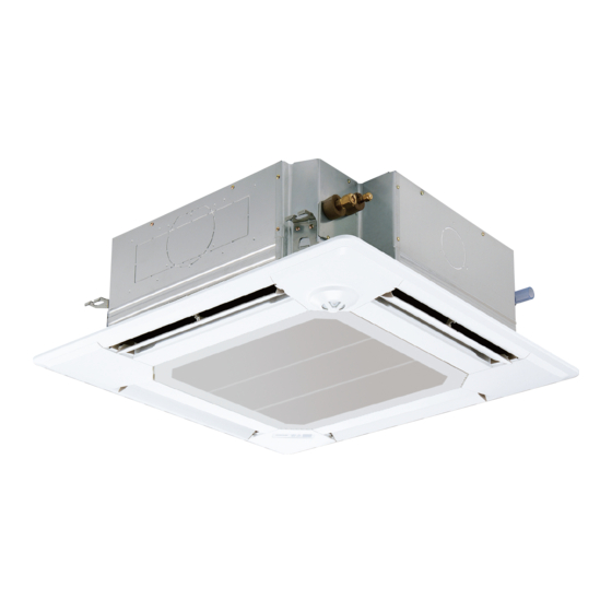
Indoor unit
[Model names]
PLA-A12AA
PLA-A18AA
PLA-A24AA
PLA-A30AA
PLA-A36AA
PLA-A42AA
Model name
indication
INDOOR UNIT
ON/OFF
TEMP
WIRELESS REMOTE
CONTROLLER
[Service Ref.]
PLA-A12AA PLA-A12AA
PLA-A18AA PLA-A18AA
PLA-A24AA PLA-A24AA
PLA-A30AA PLA-A30AA
PLA-A36AA PLA-A36AA
PLA-A42AA PLA-A42AA
TEMP.
ON/OFF
WIRED REMOTE
CONTROLLER
1
1
1
1
1
1
CONTENTS
1. TECHNICAL CHANGES ··································2
2. REFERENCE MANUAL ······································2
3. SAFETY PRECAUTION···································3
4. PART NAMES AND FUNCTIONS ···················5
5. SPECIFICATIONS ············································8
6. NOISE CRITERION CURVES ························10
7. OUTLINES AND DIMENSIONS ·····················11
8. WIRING DIAGRAM············································12
9. REFRIGERANT SYSTEM DIAGRAM ··················13
10. TROUBLESHOOTING ···································14
11. DISASSEMBLY PROCEDURE·······················30
12. PARTS LIST ···················································33
13. RoHS PARTS LIST ········································38
3 3 2 2 3
June 2007
No. OC370
REVISED EDITION-B
Revision:
• WIRING DIAGRAM has been
changed in REVISED EDI-
TION-B.
• Some descriptions have been
modified.
• Please void OC370 REVISED
EDITION-A.
NOTE:
• This manual describes only
service data of the indoor
units.
• RoHS compliant products
have <G> mark on the spec
name plate.
• For servicing RoHS compliant
products, refer to the RoHS
PARTS LIST.
Advertisement
Table of Contents

Related Manuals for Mitsubishi Electric PUZ-A NHA Series


Summary of Contents for Mitsubishi Electric PUZ-A NHA Series
-
Page 1: Table Of Contents
SPLIT-TYPE, HEAT PUMP AIR CONDITIONERS SPLIT-TYPE, AIR CONDITIONERS June 2007 No. OC370 REVISED EDITION-B SERVICE MANUAL Revision: • WIRING DIAGRAM has been Indoor unit changed in REVISED EDI- [Model names] [Service Ref.] TION-B. • Some descriptions have been PLA-A12AA PLA-A12AA modified. -
Page 2: Technical Changes
TECHNICAL CHANGES PLA-A12AA PLA-A12AA PLA-A18AA PLA-A18AA PLA-A24AA PLA-A24AA PLA-A30AA PLA-A30AA PLA-A36AA PLA-A36AA PLA-A42AA PLA-A42AA • Indoor controller board has been changed. REFERENCE MANUAL 2-1. OUTDOOR UNIT SERVICE MANUAL Service Manual No. Service Ref. PUZ-A18/24/30/36/42NHA PUZ-A18/24/30/36/42NHA-BS OC367 PUY-A12/18/24/30/36/42NHA PUY-A12/18/24/30/36/42NHA 2-2. TECHNICAL DATA BOOK Manual No. -
Page 3: Safety Precaution
SAFETY PRECAUTION 3-1. ALWAYS OBSERVE FOR SAFETY Before obtaining access to terminals, all supply circuits must be disconnected. 3-2. CAUTIONS RELATED TO NEW REFRIGERANT Cautions for units utilising refrigerant R410A Use new refrigerant pipes. Do not use refrigerant other than R410A. If other refrigerant (R22 etc.) is used, chlorine in refrige- rant can cause deterioration of refrigerant oil etc. - Page 4 [2] Additional refrigerant charge When charging directly from cylinder · Check that cylinder for R410A on the market is syphon type. · Charging should be performed with the cylinder of syphon stood vertically. (Refrigerant is charged from liquid phase.) Unit Gravimeter [3] Service tools Use the below service tools as exclusive tools for R410A refrigerant.
-
Page 5: Part Names And Functions
PART NAMES AND FUNCTIONS Indoor Unit Filter Removes dust and pollutants from intake air. Horizontal Air Outlet Sets horizontal airflow automatically during cooling or dehumidifying. Grille Auto Air Swing Vane Disperses airflow up and down and adjusts the angle of airflow direction. Air Intake Intakes air from room. - Page 6 Wired remote controller Display Section Day-of-Week “Sensor” indication For purposes of this explanation, Shows the current day of the week. Displayed when the remote controller all parts of the display are shown sensor is used. as lit. During actual operation, only the relevant items will be lit.
-
Page 7: Wireless Remote Controller
Wireless remote controller display CHECK TEST RUN Indicate that the unit is being checked or test-run. display display MODEL SELECT Blinks when model is selected. Lights up while the signal is transmitted to the indoor unit when the button is pressed. Temperature setting display indicates the desired temperature setting which is set. -
Page 8: Specifications
SPECIFICATIONS Service Ref. PLA-A12AA/ PLA-A12AA Power supply (phase, cycle, voltage) Single phase,60Hz, 208/230V Max. Fuse Size Min. Circuit Ampacity External finish (Panel) Munsell 0.70Y 8.59/0.97 Heat exchanger Plate fin coil Fan (drive) o No. Turbo fan (direct) o 1 Fan motor output 0.070 Fan motor F.L.A. - Page 9 Service Ref. PLA-A30AA/ PLA-A30AA Power supply (phase, cycle, voltage) Single phase,60Hz, 208/230V Max. Fuse Size Min. Circuit Ampacity External finish (Panel) Munsell 0.70Y 8.59/0.97 Heat exchanger Plate fin coil Fan (drive) o No. Turbo fan (direct) o 1 Fan motor output 0.070 F.L.A.
-
Page 10: Noise Criterion Curves
NOISE CRITERION CURVES PLA-A12AA PLA-A18AA PLA-A18AA NOTCH SPL(dB) LINE NOTCH SPL(dB) LINE High High PLA-A12AA PLA-A24AA PLA-A24AA Medium1 Medium1 PLA-A30AA PLA-A30AA Medium2 Medium2 NC-70 NC-70 NC-60 NC-60 NC-50 NC-50 NC-40 NC-40 NC-30 NC-30 APPROXIMATE APPROXIMATE THRESHOLD OF THRESHOLD OF HEARING FOR HEARING FOR NC-20 NC-20... -
Page 11: Outlines And Dimensions
OUTLINES AND DIMENSIONS INDOOR UNIT PLA-A12AA PLA-A18AA PLA-A24AA PLA-A12AA PLA-A18AA PLA-A24AA PLA-A30AA PLA-A36AA PLA-A42AA PLA-A30AA PLA-A36AA PLA-A42AA Unit : inch(mm) Branch duct hole (Cut out hole) 3-15/16(100) 3-15/16(100) 3-17/32(90) 3-17/32(90) Ceiling hole Ceiling hole 25/32~1-25/32(20~45) 33-27/32~35-13/16(860~910) 25/32~1-25/32(20~45) 31-7/8(810) 31-7/8(810) 31-7/8(810) 31-7/8(810) 31-7/8(810) Fresh air intake... -
Page 12: Wiring Diagram
WIRING DIAGRAM PLA-A12AA PLA-A18AA PLA-A24AA PLA-A30AA PLA-A36AA PLA-A42AA PLA-A12AA PLA-A18AA PLA-A24AA PLA-A30AA PLA-A36AA PLA-A42AA [LEGEND] SYMBOL NAME SYMBOL NAME SYMBOL NAME INDOOR POWER BOARD CAPACITOR<FAN MOTOR> WIRELESS REMOTE CONTROLLER BOARD INDOOR CONTROLLER BOARD DRAIN-UP MACHINE BUZZER FAN CONTROL ELEMENT DRAIN SENSOR LED1 LED<RUN INDICATOR >... -
Page 13: Refrigerant System Diagram
REFRIGERANT SYSTEM DIAGRAM PLA-A12AA PLA-A18AA PLA-A24AA PLA-A30AA PLA-A36AA PLA-A42AA PLA-A12AA PLA-A18AA PLA-A24AA PLA-A30AA PLA-A36AA PLA-A42AA Strainer (#50) Heat exchanger Refrigerant GAS pipe connection (Flare) Thermistor TH5 (Cond./ Eva. temperature) Refrigerant flow in cooling Refrigerant flow in heating Refrigerant LIQUID pipe connection (Flare) Thermistor TH2 Pipe temperature (Liquid) -
Page 14: Troubleshooting
TROUBLESHOOTING 10-1. TROUBLESHOOTING <Error code display by self-diagnosis and actions to be taken for service (summary)> Present and past error codes are logged and displayed on the wired remote controller or controller board of outdoor unit. Actions to be taken for service and the inferior phenomenon reoccurrence at field are summarized in the table below. Check the contents below before investigating details. - Page 15 10-2. MALFUNCTION-DIAGNOSIS METHOD BY REMOTE CONTROLLER <In case of trouble during operation> When a malfunction occurs to the air conditioner, both indoor unit and outdoor unit will stop and operation lamp blinks to inform unusual stop. < Malfunction-diagnosis method at maintenance service> [Procedure] 1.
- Page 16 • Refer to the following tables for details on the check codes. [Output pattern A] Beeper sounds Beep Beep Beep Beep Beep Beep Beep OPERATION · · · Repeated INDICATOR lamp blinking pattern Approx. 2.5 sec. 0.5 sec. 0.5 sec. 0.5 sec.
- Page 17 • On wireless remote controller The continuous buzzer sounds from receiving section of indoor unit. Blink of operation lamp • On wired remote controller 1Check code displayed in the LCD. • If the unit cannot be operated properly after the test run has been performed, refer to the following table to find out the cause. Symptom Cause Wired remote controller...
- Page 18 Note: Refer to the manual of outdoor unit for the details of display 10-3. SELF-DIAGNOSIS ACTION TABLE such as F, U, and other E. Abnormal point and detection method Countermeasure Error Code Cause Room temperature thermistor (TH1) 1 Defective thermistor 1–3 Check resistance value of thermistor.
- Page 19 Abnormal point and detection method Countermeasure Error Code Cause Freezing/overheating protection is (Cooling or drying mode) (Cooling or drying mode) working 1 Clogged filter (reduced airflow) 1 Check clogs of the filter. 1 Freezing protection (Cooling mode) 2 Short cycle of air path 2 Remove shields.
- Page 20 Abnormal point and detection method Countermeasure Error Code Cause Pipe temperature thermistor / 1 Defective thermistor 1–3 Check resistance value of thermistor. Condenser-Evaporator (TH5) characteristics For characteristics, refer to (P1) above. 2 Check contact failure of connector (CN29) 1 The unit is in 3-minute resume protec- 2 Contact failure of connector on the indoor controller board.
- Page 21 Abnormal point and detection method Countermeasure Error Code Cause ∗ Check LED display on the outdoor control cir- Indoor/outdoor unit communication 1 Contact failure, short circuit or, error (Signal receiving error) cuit board. (Connect A-control service tool, miswiring (converse wiring) of 1 Abnormal if indoor controller board PAC-SK52ST.) indoor/outdoor unit connecting...
- Page 22 10-4. TROUBLESHOOTING BY INFERIOR PHENOMENA Note: Refer to the manual of outdoor unit for the detail of remote controller. Phenomena Cause Countermeasure (1)LED2 on indoor controller board • When LED1 on indoor controller board is also off. 1 Power supply of rated voltage is not supplied to out- 1 Check the voltage of outdoor power is off.
- Page 23 Note: Refer to the manual of outdoor unit for the detail of remote controller. Phenomena Cause Countermeasure (1)LED2 on indoor controller board • When LED1 on indoor controller board is lit. 1 Mis-setting of refrigerant address for outdoor unit 1 Check the setting of refrigerant address is off.
-
Page 24: Emergency Operation
10-5. EMERGENCY OPERATION 10-5-1. When wireless remote controller has troubles or its battery is exhausted 1. Emergency operation is available in such a case using emergency operation switch equipped on the grille. 2. To start operation • Cooling Operation·······Press (Cooling) switch. Heating Operation·······Press (Heating) switch. - Page 25 10-6. HOW TO CHECK THE PARTS PLA-A12AA PLA-A18AA PLA-A24AA PLA-A30AA PLA-A36AA PLA-A42AA PLA-A12AA PLA-A18AA PLA-A24AA PLA-A30AA PLA-A36AA PLA-A42AA Parts name Check points Room temperature Disconnect the connector then measure the resistance using a tester. thermistor (TH1) (At the ambient temperature 10:(50˚F)~30:(86˚F)) Pipe temperature Normal Abnormal...
- Page 26 <Thermistor Characteristic graph> Room temperature thermistor(TH1) Thermistor for <Thermistor for lower temperature> Pipe temperature thermistor/liquid(TH2) lower temperature Condenser/evaporator temperature thermistor(TH5) Thermistor R =15k' ± 3% Fixed number of B=3480 ± 2% t(:):Rt=15exp { 3480( 273+t T(˚F):Rt=15exp { 3480( T-32 273+ 0: (32˚F) 15k' 10: (50˚F)
- Page 27 10-7.TEST POINT DIAGRAM 10-7-1. Power board PLA-A12AA PLA-A18AA PLA-A24AA PLA-A30AA PLA-A36AA PLA-A42AA PLA-A12AA PLA-A18AA PLA-A24AA PLA-A30AA PLA-A36AA PLA-A42AA CN2S Connect to the indoor controller board (CN2D) between 1 to 3 12.6-13.7V DC (Pin1 (+)) CNSK Connect to the indoor controller board (CNDK) between 1 to 3 208/230V AC...
- Page 28 10-7-2. Indoor controller board PLA-A12AA PLA-A18AA PLA-A24AA PLA-A30AA PLA-A36AA PLA-A42AA PLA-A12AA PLA-A18AA PLA-A24AA PLA-A30AA PLA-A36AA PLA-A42AA LED1 LED2 CN2D LED3 Power supply (I.B) Power supply (R.B) Connect to the indoor power board Transmission (Indoor/outdoor) (CN2S) (12.5~13.7V DC) CN22 Connect to the terminal CN3C block(TB5) Transmission...
- Page 29 10-8. FUNCTIONS OF DIP SWITCH AND JUMPER WIRE Each function is controlled by the dip switch and the jumper wire on control P.C. board. SW1 and SW2 are equipped only for service parts. Model setting and capacity setting are memorized in the nonvolatile memory of the control P.C. board of the unit.
-
Page 30: Disassembly Procedure
DISASSEMBLY PROCEDURE PLA-A12AA PLA-A18AA PLA-A24AA PLA-A30AA PLA-A36AA PLA-A42AA PLA-A12AA PLA-A18AA PLA-A24AA PLA-A30AA PLA-A36AA PLA-A42AA Be careful on removing heavy parts. OPERATING PROCEDURE PHOTOS & ILLUSTRATIONS 1. Removing the air intake grille Figure 1 (1) Slide the knob of air intake grille to the direction of the arrow 1 to open the air intake grille. - Page 31 OPERATING PROCEDURE PHOTOS & ILLUSTRATIONS 4. Removing the fan motor Fan motor Photo 3 (1) Remove the bell mouth.(See photo 1) (2) Remove the electrical box.(See photo 2) (3) Remove the turbo fan nut. (4) Pull out the turbo fan. (5) Disconnect the connector of the fan motor lead wire.
- Page 32 OPERATING PROCEDURE PHOTOS & ILLUSTRATIONS 8. Removing the drain pump and drain sensor Photo 7 (1) Remove the panel. (See photo 5) (2) Remove the bell mouth. (See photo 1) (3) Remove the electrical box. (See photo 2) (4) Remove the drain pan. (See photo 6) (5) Remove the 3 screws of the drain pump.
-
Page 33: Parts List
PARTS LIST (non-RoHS compliant) PANEL PARTS PLA-A12AA PLA-A18AA PLA-A24AA PLA-A30AA PLA-A36AA PLA-A42AA GEAR GEAR (VANE) VANE BUSH VANE MOTOR CENTRALLY CONTROLLED 1Hr. ON OFF ˚C CLOCK CHECK FILTER CHECK MODE ˚C TEST RUN STAND BY ERROR CODE DEFROST NOT AVAILABLE FUNCTION TEMP. - Page 34 FUNCTIONAL AND STRUCTURAL PARTS PLA-A12AA PLA-A18AA PLA-A24AA PLA-A30AA MOTOR CAP SPL WASHER CONDENSER EVAPORATOR TEMPERATURE THERMISTOR PIPE TEMPERATURE THERMISTOR Q'ty / set Wiring Recom- Remarks PLA-A·AA Parts No. Specification Parts Name Diagram mended (Drawing No.) Symbol Q'ty 24, 30 TURBO FAN SPL WASHER T7W H20 480 HEAT EXCHANGER...
- Page 35 FUNCTIONAL AND STRUCTURAL PARTS PLA-A36AA PLA-A42AA MOTOR CAP SPL WASHER CONDENSER EVAPORATOR TEMPERATURE THERMISTOR PIPE TEMPERATURE THERMISTOR Q'ty / set Wiring Recom- Remarks PLA-A·AA Parts No. Specification Parts Name Diagram mended (Drawing No.) Symbol Q'ty 36, 42 TURBO FAN SPL WASHER T7W H22 480 HEAT EXCHANGER PIPE TEMPERATURE THERMISTOR...
- Page 36 FUNCTIONAL AND STRUCTURAL PARTS PLA-A12AA PLA-A18AA PLA-A24AA PLA-A30AA DRAIN PLUG DRAIN PLUG CAPACITOR TERMINAL BLOCK TERMINAL BLOCK TERMINAL BLOCK ROOM TEMPERATURE THERMISTOR Q'ty / set Wiring Recom- Remarks Parts No. Specification PLA-A·AA Parts Name Diagram mended (Drawing No.) Symbol Q'ty 12, 18, 24, 30 DRAIN PAN DRAIN HOSE...
- Page 37 FUNCTIONAL AND STRUCTURAL PARTS PLA-A36AA PLA-A42AA DRAIN PLUG DRAIN PLUG CAPACITOR TERMINAL BLOCK TERMINAL BLOCK TERMINAL BLOCK ROOM TEMPERATURE THERMISTOR Q'ty / set Wiring Recom- Remarks Parts No. Parts Name Specification Diagram mended PLA-A·AA (Drawing No.) Symbol Q'ty 36, 42 T7W E07 529 DRAIN PAN T7W E00 527...
-
Page 38: Rohs Parts List
RoHS PARTS LIST PANEL PARTS PLA-A12AA PLA-A18AA PLA-A24AA GEAR PLA-A30AA PLA-A36AA PLA-A42AA GEAR (VANE) VANE BUSH VANE MOTOR CENTRALLY CONTROLLED 1Hr. ON OFF ˚C CHECK CLOCK FILTER CHECK MODE ˚C TEST RUN STAND BY ERROR CODE DEFROST NOT AVAILABLE FUNCTION TEMP. - Page 39 FUNCTIONAL AND STRUCTURAL PARTS PLA-A12AA PLA-A18AA PLA-A24AA PLA-A30AA MOTOR CAP SPL WASHER CONDENSER EVAPORATOR TEMPERATURE THERMISTOR PIPE TEMPERATURE THERMISTOR Q'ty / set Wiring Recom- Remarks Parts No. Specification PLA-A·AA Parts Name Diagram mended (Drawing No.) Symbol Q'ty 18 24, 30 TURBO FAN SPL WASHER T7W H20 480...
- Page 40 FUNCTIONAL AND STRUCTURAL PARTS PLA-A36AA PLA-A42AA MOTOR CAP SPL WASHER CONDENSER EVAPORATOR TEMPERATURE THERMISTOR PIPE TEMPERATURE THERMISTOR Q'ty / set Wiring Recom- Remarks Specification PLA-A·AA Parts No. Parts Name Diagram mended (Drawing No.) Symbol Q'ty 36, 42 TURBO FAN R01 09K 097 SPL WASHER T7W H22 480 HEAT EXCHANGER...
- Page 41 FUNCTIONAL AND STRUCTURAL PARTS PLA-A12AA PLA-A18AA PLA-A24AA PLA-A30AA DRAIN PLUG DRAIN PLUG CAPACITOR TERMINAL BLOCK TERMINAL BLOCK TERMINAL BLOCK ROOM TEMPERATURE THERMISTOR Q'ty / set Wiring Recom- Remarks Parts No. Specification PLA-A·AA Parts Name Diagram mended (Drawing No.) Symbol Q'ty 12, 18, 24, 30 T7W E26 529 DRAIN PAN...
- Page 42 FUNCTIONAL AND STRUCTURAL PARTS PLA-A36AA PLA-A42AA DRAIN PLUG DRAIN PLUG CAPACITOR TERMINAL BLOCK TERMINAL BLOCK TERMINAL BLOCK ROOM TEMPERATURE THERMISTOR Q'ty / set Wiring Recom- Remarks Parts No. Parts Name Specification PLA-A·AA Diagram mended (Drawing No.) Symbol Q'ty 36, 42 T7W E28 529 DRAIN PAN T7W E02 527...
- Page 44 HEAD OFFICE : TOKYO BLDG., 2-7-3, MARUNOUCHI, CHIYODA-KU, TOKYO 100-8310, JAPAN CCopyright 2006 MITSUBISHI ELECTRIC ENGINEERING CO., LTD. New publication, effective Jun. 2007 Distributed in Jun. 2007 No.OC370 REVISED EDITION-B PDF 9 Specifications subject to change without notice. Distributed in Aug. 2006 No.OC370 REVISED EDITION-A PDF 9 Distributed in Feb.