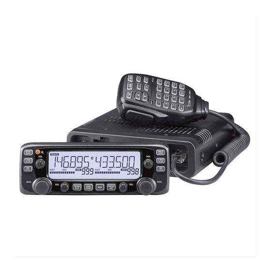
Icom IC-2730A Service Manual
Dual band transceiver
Hide thumbs
Also See for IC-2730A:
- Instruction manual (96 pages) ,
- Instruction manual (10 pages) ,
- Programming manual (2 pages)
Table of Contents
Advertisement
Advertisement
Table of Contents

Related Manuals for Icom IC-2730A


Summary of Contents for Icom IC-2730A
- Page 1 DUAL BAND TRANSCEIVER S-15120XZ-C1 March 2015...
- Page 2 8. READ the instructions of the test equipment thoroughly before connecting it to the transceiver. Icom, Icom Inc. and the Icom logo are registered trademarks of Icom Incorporated (Japan) in Japan, the United States, the United Kingdom, Germany, France, Spain, Russia, Australia, New Zealand, and/or other countries.
-
Page 3: Table Of Contents
TABLE OF CONTENTS SECTION SPECIFICATIONS SECTION INSIDE VIEWS SECTION DISASSEMBLY INSTRUCTION SECTION CIRCUIT DESCRIPITON RECEIVER CIRCUITS ..................4-1 TRANSMIT CIRCUITS ..................4-5 FREQUENCY SYNTHESIZER CIRCUITS ............4-7 VOLTAGE BLOCK DIAGRAM ................4-8 SECTION ADJUSTMENT PROCEDURES PREPARATION ....................5-1 FREQUENCY ADJUSTMENT ................5-3 TRANSMIT ADJUSTMENT ................ - Page 4 SECTION 1. SPECIFICATIONS D General • Frequency coverage: 118–174 MHz* , 375–550 MHz* 144–146 MHz, 430–440 MHz 118–136.99166 MHz* , 144–146 MHz, 430–434 MHz, 435–438 MHz 144–146 MHz, 430–434 MHz, 435–438 MHz RX, TX 144–146 MHz, 430–432 MHz 118–174 MHz* , 375–550 MHz* 144–148 MHz, 430–450 MHz* RX, TX 144–146 MHz, 430–440 MHz...
- Page 5 Receiver • Receive system: Double superheterodyne system • IF frequencies: Left band 1st IF 38.85 MHz 2nd IF 450 kHz Right band 1st IF 46.35 MHz 2nd IF 450 kHz • Sensitivity (except spurious points): Amateur bands FM/FM-N (12 dB SINAD) ...
- Page 6 SECTION 2. INSIDE VIEWS • CONTROL UNIT +3.3 V REGULATOR (IC6) RESET IC (IC1) (IC5) +3.3 V REGULATOR (IC7) CLONING DATA LINE BUFFER (IC102) LCD DRIVER (IC2)
- Page 7 • MAIN UNIT (TOP VIEW) RESET IC (IC308) CLONING DATA LINE BUFFER EEPROM (IC312) (IC301) NOISE AMP (Left band) (IC123) AND LOGIC GATE IC NOISE AMP (Right band) (IC108) (IC122) AF SW MIC MUTE SW/MIC GAIN SW (IC109) (IC100) ELECTRONIC VOLUME IC VOX AMP/IDC AMP/AF LPF (IC110) (IC112)
- Page 8 • MAIN UNIT (BOTTOM VIEW) DISCRIMINATOR (Right band) (X101) 2ND IF FILTER (Right band) (FI101) 2ND IF FILTER (Right band) (FI100) TX POWER AMP (UHF band) (IC4) PLL IC (Right band) (IC206) REFERENCE FREQUENCY OSCILLATOR (Right band) (X201) DISCRIMINATOR (Left band) (X102) 2ND IF FILTER (Left band) (FI103)
- Page 9 SECTION 3. DISASSEMBLY INSTRUCTION 1. Removing the CONTROL UNIT 2. Removing the MAIN UNIT 1) Remove all knobs from the controller. 1) Remove eight screws from the top cover. 2) Remove the top cover from the chassis. Controller Screws ×8 Top cover 2) Remove four screws from the rear panel.
- Page 10 6) Unsolder three points at the antenna connector. 7) Disconnect the cooling fan cable. UNSOLDER COOLING FAN CABLE Solder remover 8) Remove total of 17 screws from the MAIN UNIT. Screws ×17 9) Remove the MAIN UNIT from the chassis. MAIN UNIT CHASSIS...
-
Page 11: Receive Circuits
SECTION 4. CIRCUIT DESCRIPTION 4-1 RECEIVE CIRCUITS RF CIRCUITS RF CIRCUITS The received signal from the antenna connector passed ANTENNA through the LPF (L90, L94, L96, C409, C418 and C428). The D68,D73, 375-550MHz 118-550MHz D84,D75 fi ltered signal is applied to either the VHF or UHF band’s RF TX/RX 400-470MHz UHF TX circuit... - Page 12 1ST IF CIRCUITS 2ND IF CIRCUITS VHF BAND • Left band • Left band IC121 is an IF IC, which contains the 2nd mixer, limiter AMP, The received signal from the RF circuit and 1st LO signal are noise AMP, quadrature detector, AM detector, AGC controller, applied to the 1st IF mixer (Q145) and mixed, resulting in the signal strength detector, and so on.
- Page 13 AM DETECTOR CIRCUITS • Left band 2ND IF AND DEMODULATOR CIRCUITS (Left band) The 2nd IF signal applied from pin 5 is amplifi ed by the IF X200 Q200 AMP, and then demodulated by the amplitude detector in the 38.4MHz 12.8MHz IF IC (IC121).
- Page 14 RX AF CIRCUITS • Left band When output from [EXTERNAL SPEAKER JACK1] The demodulated AF signal from the AF SW (IC119) is The output signal from the AF SW (IC109) is passed through passed through the AF mute SW (IC111, pins 4, 3) and AF fi l- the AF MUTE SW (Q104 and Q105), and applied to the AF ter (Q113), and then applied to the volume IC (IC110, pin 4), AMP (IC105, pin 1).
-
Page 15: Transmit Circuits
4-2 TRANSMIT CIRCUITS TX AF CIRCUIT (CONTROL AND MAIN UNITS) MODULATION CIRCUITS (MAIN UNIT) When the microphone is connected to the controller: The modulation signal from the TX AF circuit is applied to the The AF signal from the microphone is applied to the MIC VCO as the frequency modulation signal. - Page 16 TX AMP CIRCUITS (MAIN UNIT) APC CIRCUITS VHF BAND VHF BAND The TX signal from the VHF band modulation circuit is passed A portion of RF signal is rectifi ed by the power detector di- through the LPF (L50, L51, C215, C220 and C225) and ATT odes (D59 and D63) at the LPF (L67, L68, C291, C297, (R146, R147 and R151), and then sequentially amplifi...
-
Page 17: Frequency Synthesizer Circuits
VCOs The PLL circuit controls the VCO oscillating frequency by The IC-2730A/E has total of four VCOs: two VCOs for the left comparing the reference signal and the fed back VCO sig- band and another two for the right band. -
Page 18: Voltage Block Diagram
4-4 VOLTAGE BLOCK DIAGRAM Voltage from the power supply is routed throughout the transceiver, through regulators and switches. W300 NOISE FANHV FILTER Q32/Q34 I SENS UTX_C IC310 CURRENT IDET DETECT Q27/Q28 VTX_C Q306 IC313 Q301/Q308 PCON CTRL VCC2 Q302 IC325 IC319 IC321 MAIN UNIT... -
Page 19: Preparation
–20 dBµ to 90 dBµ (–127 dBm to –17 dBm) DO NOT transmit while Attenuator an SSG is connected to deviation meter 40 dB the antenna connector. RF power meter 0.1–60 W/50 Ω Frequency IC-2730A/E (Rear view) counter... - Page 20 5-1 PREPARATION (Continued) Select an adjustment item using [MONI]/[LOW], and then set the adjustment value as specifi ed using [DIAL]. • ENTERING THE ADJUSTMENT MODE 1) Connect the JIG cable to [MIC] on the main unit. (See page 5-1.) 2) While holding down both [MAIN BAND], turn ON the power. Main unit (front view) 1) Connect the JIG cable to [MIC].
-
Page 21: Frequency Adjustment
5-2 FREQUENCY ADJUSTMENT Select an adjustment item using [DUP MONI]/[LOW DTMF], and then set the adjustment value as specifi ed using [DIAL]. ADJUSTMENT ADJUSTMENT OPERATION VALUE ITEM REFERENCE 1) Connect a power meter or dummy load to the antenna connec- FREQUENCY tor. - Page 22 5-3 TRANSMIT ADJUSTMENTS (Continued) Select an adjustment item using [DUP MONI]/[LOW DTMF], and then set the adjustment value as specifi ed using [DIAL]. ADJUSTMENT ADJUSTMENT OPERATION VALUE ITEM 1 1) Connect a modulation analyzer to the antenna connector through MODULATION BALANCE an attenuator, and then set it as;...
-
Page 23: Receive Adjustment
5-4 RECEIVE ADJUSTMENTS 1) Select an adjustment item (band) using [DUP MONI]/[LOW DTMF]. 2) Set the SSG’ frequency as specifi ed, and then push [MW] to automatically adjust. ADJUSTMENT ADJUSTMENT OPERATION VALUE ITEM RECEIVE NOTE: “RECEIVE SENSITIVITY” must be adjusted before “S-METER.” Otherwise, “S-METER” will SENSITIVITY not be adjusted properly. - Page 24 5-4 RECEIVE ADJUSTMENTS (Continued) ADJUSTMENT ADJUSTMENT OPERATION VALUE ITEM S-METER NOTE: “RECEIVE SENSITIVITY” must be adjusted before “S-METER.” Otherwise, “S-METER” will not be adjusted properly. 1 • Connect an SSG to the antenna connector, and then set it as: – –...
- Page 25 5-4 RECEIVE ADJUSTMENTS (Continued) ADJUSTMENT ADJUSTMENT OPERATION VALUE ITEM -435.020/450.020 MHz- 38 • Set the SSG as: Push [MW]. [S39] (NAR) Frequency: (Set the same frequency displayed on the controller.) (FM-N mode) (Automatic [Left band] † Level 0 dBµ (–107 dBm) adjustment) [Right band] [S39] (NAR)
- Page 26 SECTION 6. PARTS LIST [CONTROL UNIT] [CONTROL UNIT] PARTS PARTS DESCRIPTION DESCRIPTION LOCATION LOCATION 1130017740 S.IC HT16C24/YG-LQFP80 87.8/61.6 4030016930 S.CER C1005 JB 1A 104K-T 68.2/19.8 1180004490 S.REG XC6209F332MR-G 32.0/29.6 4030016930 S.CER C1005 JB 1A 104K-T 67.0/18.7 1180004490 S.REG XC6209F332MR-G 64.9/12.7 4030016930 S.CER C1005 JB 1A 104K-T 53.2/16.0 IC102...
- Page 27 [MAIN UNIT] [MAIN UNIT] PARTS PARTS DESCRIPTION DESCRIPTION LOCATION LOCATION 1130016460 S.IC R2A20169SA 59.0/21.0 Q141 1590004050 S.TRA LDTA144EET1G <SLVJ> 19.8/21.6 1110008910 S.IC NJM2904CV-TE1-#HMZR 89.6/28.9 Q142 1590004050 S.TRA LDTA144EET1G <SLVJ> 60.8/21.6 1150002423 IC RA60H1317M1A-222 Q143 1580000731 S.FET 3SK293(TE85LF) 20.8/68.6 1150002400 IC RA60H4047M1-121 Q144 1580000731 S.FET...
- Page 28 [MAIN UNIT] [MAIN UNIT] PARTS PARTS DESCRIPTION DESCRIPTION LOCATION LOCATION 1720000701 S.VAR 1SV305(TPL3F) 42.1/67.0 X102 6070000300 S.DIS JTBM450CX24 <JJE> 54.1/33.2 1720000701 S.VAR 1SV305(TPL3F) 36.6/66.7 X200 6050013940 S.XTA CR-994 NT3225SA 12.8 MHz 74.8/12.8 D100 1750001810 S.DIO L1SS400T1G <SLVJ> 20.5/13.1 X201 6050013930 S.XTA CR-993 NT3225SA 15.3 MHz 36.9/14.9 D101...
- Page 29 [MAIN UNIT] [MAIN UNIT] PARTS PARTS DESCRIPTION DESCRIPTION LOCATION LOCATION L327 6190002030 S.COI MLG1608S 1R0J-T 40.4/24.9 R135 7030005090 S.RES ERJ2GEJ 104 X (100K) 100.9/112.5 L328 6200013460 S.COI C2012H-10NH-R-0231 41.9/31.4 R136 7030005120 S.RES ERJ2GEJ 102 X (1K) 99.4/109.2 L329 6200015290 S.COI C2012H-5N6D-R-0231 45.2/31.1 R137...
- Page 30 [MAIN UNIT] [MAIN UNIT] PARTS PARTS DESCRIPTION DESCRIPTION LOCATION LOCATION R348 7030007290 S.RES ERJ2GEJ 222 X (2.2K) 117.2/10.1 R487 7030005050 S.RES ERJ2GEJ 103 X (10K) 105.3/31.8 R352 7030008010 S.RES ERJ2GEJ 123 X (12K) 133.1/104.5 R488 7030005050 S.RES ERJ2GEJ 103 X (10K) 105.3/38.3 R354 7030000100 S.RES MCR10EZHJ 4.7 (4R7)
- Page 31 [MAIN UNIT] [MAIN UNIT] PARTS PARTS DESCRIPTION DESCRIPTION LOCATION LOCATION R612 7030005090 S.RES ERJ2GEJ 104 X (100K) 97.9/25.6 R786 7030007060 S.RES ERJ2GEJ 684X (680K) 28.9/25.8 R613 7030007290 S.RES ERJ2GEJ 222 X (2.2K) 100.9/10.9 R787 7030005050 S.RES ERJ2GEJ 103 X (10K) 33.6/15.0 R614 7030005100 S.RES ERJ2GEJ 154 X (150K)
- Page 32 [MAIN UNIT] [MAIN UNIT] PARTS PARTS DESCRIPTION DESCRIPTION LOCATION LOCATION R992 7030005090 S.RES ERJ2GEJ 104 X (100K) 124.8/23.0 4030017600 S.CER C1005 CH 1H 080C-T 34.6/71.3 R994 7030005090 S.RES ERJ2GEJ 104 X (100K) 123.2/23.9 4030017580 S.CER C1005 CH 1H 060C-T 12.4/92.3 R997 7030005090 S.RES ERJ2GEJ 104 X (100K) 124.7/28.3...
- Page 33 [MAIN UNIT] [MAIN UNIT] PARTS PARTS DESCRIPTION DESCRIPTION LOCATION LOCATION C234 4030016930 S.CER C1005 JB 1A 104K-T 76.6/41.1 C402 4030011100 S.CER GRM31M2C2H8R0DV01L C235 4030017350 S.CER C1005 CH 1H 020B-T 75.0/38.1 (GRM42-6) 44.5/120.7 C236 4030017460 S.CER C1005 JB 1H 102K-T 30.9/34.9 C405 4030017650 S.CER C1005 CH 1H 270J-T 51.3/93.6...
- Page 34 [MAIN UNIT] [MAIN UNIT] PARTS PARTS DESCRIPTION DESCRIPTION LOCATION LOCATION C637 4030018920 S.CER C1005 JB 1H 392K-T 107.7/59.5 C784 4030017460 S.CER C1005 JB 1H 102K-T 13.9/41.3 C638 4030018920 S.CER C1005 JB 1H 392K-T 100.5/59.5 C785 4030020000 S.CER C1005 JB 1A 105K-T 118.8/34.5 C643 4030018080 S.CER C1005 JB 1H 182K-T...
- Page 35 [MAIN UNIT] [MAIN UNIT] PARTS PARTS DESCRIPTION DESCRIPTION LOCATION LOCATION C936 4030019560 S.CER GRM21BB31C106KE15L 86.3/39.7 C1076 4030017460 S.CER C1005 JB 1H 102K-T 33.2/25.1 C937 4030017460 S.CER C1005 JB 1H 102K-T 76.7/24.2 C1079 4030017340 S.CER C1005 CH 1H 010B-T 39.3/37.7 C938 4030017460 S.CER C1005 JB 1H 102K-T 90.1/32.4 C1080...
- Page 36 [MAIN UNIT] PARTS DESCRIPTION LOCATION C1310 4030017460 S.CER C1005 JB 1H 102K-T 54.1/13.7 C1311 4030017460 S.CER C1005 JB 1H 102K-T 40.7/13.7 C1314 4030017650 S.CER C1005 CH 1H 270J-T 44.3/6.3 C1315 4030017650 S.CER C1005 CH 1H 270J-T 44.0/9.6 C1316 4030017360 S.CER C1005 CH 1H 030B-T 46.1/7.1 C1317 4030016930 S.CER C1005 JB 1A 104K-T...
- Page 37 SECTION 7. MECHANICAL PARTS [CHASSIS PARTS] [MAIN UNIT] ORDER ORDER DESCRIPTION QTY. DESCRIPTION QTY. 6510014961 B2B-ZR-SM4-TF (LF) (SN) 8600037590 SP CABLE -1 70MM <PHL> J100 6510023110 3008L-8P8C <KIN> J101 6450001440 HSJ1403-01-010 J102 6510025940 PJ-3047S <XIN> 6510004881 MR-DSE-01-1 <GA> J103* 6510014961 B2B-ZR-SM4-TF (LF) (SN) J300 6510025950 PCB-606 (6P6C) BLACK <VKH>...
- Page 38 Tightening torque MP8(CHASSIS)×4 (8810009611) MP8(CHASSIS)×4 (8810009611) : <0.8 (N・m)> MP14(CHASSIS) (8930069590) : <0.7 (N・m)> MP1(CHASSIS) MP3(CHASSIS) (8010023321) (8110010790) : <0.6 (N・m)> : <0.5 (N・m)> W300(MAIN) (8900016020) : <0.4 (N・m)> SP1(CHASSIS) (2510001160) MP12(CHASSIS)×4 (8810010141) : <0.3 (N・m)> MP5(CHASSIS) (8110009020) MP6(CHASSIS) (8930078590) : <0.2 (N・m)>...
- Page 39 SECTION 8. BOARD LAYOUTS • CONTROL UNIT (B-8145B) (TOP VIEW) R105 DS14 DS13 DS16 DS10 EP101 EP102 EP100 J101 EP103 EP107 EP106 EP105 EP104 C106...
- Page 40 • CONTROL UNIT (B-8145B) (BOTTOM VIEW) B-8145B Q104 EP109 R127 C102 C109 C104 R125 R124 D101 MICU/D (MICUD) EXTMIC (MICSEL) (MICPTT) R106 MICE D103 D108 MICIN (98DATA) TX_DATA MICE RX_DATA...
- Page 41 J102 J101 [SP2] [ANT] [SP1] • MAIN UNIT (B-8144B) R361 (TOP VIEW) C218 B-8144B R252 t=1.6, (4) R362 C219 C216 C401 R115 C180 C197 EP113 C181 EP118 R123 C171 R101 C556 C139 EP111 C550 C168 C153 C147 C163 R1019 C1321 C154 C421 C155...
- Page 42 • MAIN UNIT (B-8144B) (BOTTOM VIEW) C372 C352 C371 C409 C428 C394 C363 C429 C392 R257 J102 C396 J101 C326 C331 C332 C338 R209 C370 C358 IC313 IC325 IC321 C364 C301 C302 C376 C585 C1343 C1333 C1298 C1344 C1334 R377 C1303 Q106 C1274...
- Page 43 SECTION 9. BLOCK DIAGRAM Q232 Q235/ Q226 Q229/Q230/Q231 Q227 D231/D233 ANTENNA D236 RIPPLE 400-470MHz BUFF D68/D73/ D223 Q238 D234/D235 D62/D67 D84/D75 375-550MHz 118-550MHz D224 D227 R_UHF DRIVE 400-470MHz TX/RX DRIVE D229 LIMITER Q221 Q236/D232 IC207/Q222 Q233 Q228 LOOP R_LV BUFF BUFF D225 D226...
- Page 44 W300 NOISE FANHV Q32/Q34 I SENS CTRLMIC UTX_C IC307 D324 IC310 REVERSE IC100 IC205 & OVER CURRENT BTMIC Q100/Q150 Q151/Q152 IC100 IC112 IC112 IC103 IC102 IDET BUFF VOLTAGE DETECT VCOMOD Q27/Q28 PROTECT MUTE MUTE IC101 VTX_C Q306 IC313 BTMICSW CMICMUTE MIC1 MIC2 MICMUTE...
- Page 45 SECTION 10. VOLTAGE DIAGRAM • CONTROL UNIT JIC-LTNN013601 4.7k 4.7k SEG51 SEG51 SEG50 SEG50 SEG49 SEG49 SEG48 SEG48 COM0 SEG47 COM0 SEG47 COM1 SEG46 COM1 SEG46 COM2 SEG45 COM2 SEG45 COM3 SEG44 COM3 SEG44 EP109 SEG0 SEG43 COM4/SEG0 SEG43 SEG1 SEG42 MMZ1005Y102CT COM5/SEG1...
- Page 46 • MAIN UNIT (1/8) 13.64V T:7.96V 2SA1362 8.02V FANHV T:7.51V T:4.09V LDTC114YE TX Hipower R132 12.71V(#01) VTX_C 13.16V(#21) T:0.69V JDP2S12CR AS100340 R168 C267 R179 R186 C360 C372 C226 R147 C233 V_LOOUT AS080647 AS080647 0.001 0.001 AS080447 1SV308 0.001 0.001 C304 C338 MT3S20P 0.001...
- Page 47 • MAIN UNIT (2/8) FANHV R:4.70V R_UAGC R_UR8 DB2S31400 R:7.83V R:5.41V PCON_V PCON_V PCON_U U-R (375-550) PCON_U R_UR8 L100 R:4.63V R_UR8 L_UR8 R_URF L_UR8 0.22U R_VR8 R:2.52V R_VR8 L_VR8 L_VR8 C139 C147 R:2.96V R:5.35V 0.22U R:1.16V 3SK293 C182 R123 3SK293 R:1.65V 0.001 8.12V...
- Page 48 • MAIN UNIT (3/8) 100k R427 VCC2 4.7k R428 5.00V R382 R385 100k 100k C593 C566 3.30V C602 R431 13.6V IC107 CLONE Pin 1:4.02V 13.6V 3.9k Pin 2:0.42V C607 LMV321IDCK Pin 3:1.03V Pin 4:4.26V C637 C643 Pin 5:4.41V IC106 Pin 6:7.76V LA4425A 0.0039 0.0018...
- Page 49 • MAIN UNIT (4/8) 2775 MP207 4.99V R_AMC R:4.90V R_R5 R_VR8 R_AGC R_R5C N:4.87V R:3.97V R525 R533 Q119 FI100 R559 R573 LDTA114EE LTWC450H R:5.08V D105 C695 C705 D109 Q133 150k Q123 2SC4738 LDTA144EE DA2S10100L DA2S10100L R:4.78V R_2LO R:0.73V C722 DA2S10100L DA2S10100L FI101 C784...
- Page 50 • MAIN UNIT (5/8) Q229 LDTC114YE R_VVCOC R_UVCOC Q231 7.99V Q226 2SC4738 EP201 3.30V MMZ1005Y102CT EP202 7.15V R794 MMZ1005Y102CT Q230 DMA501010 4.99V LDTC114YE R822 4.7k R866 RVCO R859 X201 C1029 PDN2 SWIN 560k C1137 PDN1 0.001 R782 REFIN IC206 AK1542A R_REF VCON 0.001...
- Page 51 • MAIN UNIT (6/8) 3.30V Q208 LVCO LDTC114YE L_VVCOC L_UVCOC Q212 2SC4738 8.00V Q206 4.99V R712 7.25V DMA501010 Q209 LDTC114YE R737 4.7k R865 R700 L_REF CR-994 C915 C1138 0.001 0.001 PDN2 SWIN VCON AK1542A PDN1 IC201 X200 REFIN 12.8MHz TEST2 PVSS GPO1 BIAS...
- Page 52 • MAIN UNIT (7/8) IC321 IC310 R1005 XC6701D802JR MICMUTE MICMUTE DTMUTE DTMUTE URX_RPT URX_RPT VRX_RPT *R1002 VRX_RPT INA199B1DCK 0.003 FANHV Q306 VCC2 IC313 2SB1132L 13.6V NJM7808DL1A 8.01V R1031 R_UNLK R_UNLK L_UNLK L_UNLK L_RMUTE L_RMUTE AF_SW W300 AF_SW CTH30V222S15A AF_RSW Q302 AF_RSW C1274 R_RMUTE...
- Page 53 • MAIN UNIT (8/8) D334 LRB706F LRB706F D339 *D322 *D321 *D319 BAND1 RXF0 M-REP *D316 *D314 100k BAND2 RXF1 *D317 *D315 *D313 BAND3 VTXF TXPOW R1104 *D309 *D307 R1096 100k BAND4 UTXF EP306 R1103 3.28V MMZ1005Y102CT PB6/AN6/DA0 PB7/AN7/DA1 P96/FTIOC3 AVCC P95/FTIOB3 PCON AVref...
- Page 54 Highway 17A Delta, B.C., V4K 5B8, Canada : http://www.icomspain.com Phone : +1 (604) 952-4266 Fax : +1 (604) 952-0090 E-mail : icom@icomspain.com : http://www.icomcanada.com E-mail : info@icomcanada.com Blacksole House, Altira Park, Herne Bay, Kent CT6 6GZ, UK Phone : +44 (0) 1227 741741...
- Page 55 S-15120XZ-C1 1-1-32, Kamiminami, Hirano-ku, Osaka 547-0003, Japan © 2015 Icom Inc.