Table of Contents
Advertisement
Quick Links
Black Box Tech Support: FREE! Live. 24/7.
Tech support the
way it should be.
About Black Box
Black Box Network Services is your source for more than 118,000 networking
and infrastructure products. You'll find everything from cabinets and racks and
power and surge protection products to media converters and Ethernet switches
all supported by free, live 24/7 Tech support available in 20 seconds or less.
Copyright 2009. All rights reserved.
©
Great tech support is just 20 seconds away at
724-746-5500 or blackbox.com.
724-746-5500 | blackbox.com
Advertisement
Table of Contents

Related Manuals for Black Box AC3010A


Summary of Contents for Black Box AC3010A
- Page 1 724-746-5500 or blackbox.com. About Black Box Black Box Network Services is your source for more than 118,000 networking and infrastructure products. You’ll find everything from cabinets and racks and power and surge protection products to media converters and Ethernet switches all supported by free, live 24/7 Tech support available in 20 seconds or less.
- Page 2 Order toll-free in the U.S.: Call 877-877-BBOX (outside U.S. call 724-746-5500) • Customer FREE technical support 24 hours a day, 7 days a week: Call 724-746-5500 or fax Support 724-746-0746 • Mailing address: Black Box Corporation, 1000 Park Drive, Lawrence, Information PA 15055-1018 • Web site: www.blackbox.com • E-mail: info@blackbox.com...
- Page 3 FCC and NOM Statements FEDERAL COMMUNICATIONS COMMISSION AND INDUSTRY CANADA RADIO FREQUENCY INTERFERENCE STATEMENTS This equipment generates, uses, and can radiate radio-frequency energy, and if not installed and used properly, that is, in strict accordance with the manufacturer’s instructions, may cause inter ference to radio communication. It has been tested and found to comply with the limits for a Class A computing device in accordance with the specifications in Subpart B of Part 15 of FCC rules, which are designed to provide reasonable protection against such interference...
- Page 4 HD View HDMI 5. El aparato eléctrico no deberá ser usado cerca del agua—por ejemplo, cerca de la tina de baño, lavabo, sótano mojado o cerca de una alberca, etc.. 6. El aparato eléctrico debe ser usado únicamente con carritos o pedestales que sean recomendados por el fabricante.
- Page 5 NOM Statement 17. Cuidado debe ser tomado de tal manera que objectos liquidos no sean derramados sobre la cubierta u orificios de ventilación. 18. Servicio por personal calificado deberá ser provisto cuando: A: El cable de poder o el contacto ha sido dañado; u B: Objectos han caído o líquido ha sido derramado dentro del aparato;...
- Page 6 HD View HDMI TRADEMARKS USED IN THIS MANUAL Black Box and the Double Diamond logo are registered trademarks of BB Technologies, Inc. Any other trademarks mentioned in this manual are acknowledged to be the property of the trademark owners. Page 4...
-
Page 7: Table Of Contents
3.5.4 Restoring the Default DDC Data ..........20 3.6 Connecting to the Power Supply ............21 3.7 Repeater Application ................21 3.8 Adjusting the Video and Audio ............21 4. Troubleshooting ..................22 4.1 Problems/Solutions ................22 4.2 Calling Black Box ................22 4.3 Shipping and Packaging..............23 Page 5 724-746-5500 | blackbox.com... -
Page 8: Specifications
HD View HDMI 1. Specifications Audio: HDMI formats Cascade/Daisychain: Cascade up to 7 repeaters at 825 feet (250 m) CAT5 Cable Length (Maximum): 192 ft. (60 m); With cascading: 825 ft. (250 m) Input DDC Signal: 5-volt P-P (TTL) Input Video Signal: 1.2-volt P-P Resolution (Maximum): HDTV 1080p, 1920 x 1080 @ 60 Hz (16:09) HD System Cable: CAT5/6/7 UTP/FTP/STP cable, 24 AWG, solid wire Video Amplifier Bandwidth: 165 MHz... -
Page 9: Overview
Electronics Control (CEC) support (using two CAT5 cables in an extension application). 2.3 What’s Included Your package should contain the following items. If anything is missing or dam- aged, contact Black Box Technical Support at 724-746-5500. • Transmitter • Receiver • (2) power supplies •... -
Page 10: Transmitter
HD View HDMI 2.4 Transmitter 2.4.1 Side 1 of Transmitter Figure 2-1 illustrates the transmitter‘s side 1. Table 2-1 describes its components. Figure 2-1. Transmitter, side 1. Table 2-1. Components on transmitter side 1. Component Description Get button Press and hold to restore the default data. Stored/screen Player reads data from data previously stored in selector DIP switch... -
Page 11: Side 2
Chapter 2: Overview 2.4.2 Side 2 of Transmitter Figure 2-2 shows the components on the transmitter’s side 2. Table 2-2 describes these components. Figure 2-2. Transmitter, side 2. Table 2-2. Components on transmitter side 2. Component Description RJ-45 connector Video out port RJ-45 connector DDC port Video out port LED 1... -
Page 12: Receiver
HD View HDMI 2.5 Receiver Figures 2-3 and 2-4 illustrate the two sides of the receiver. Tables 2-3 and 2-4 describe the components. 2.5.1 Receiver’s Side 1 Figure 2-3. Receiver, side 1. Table 2-3. Components on receiver‘s side 1. Component Description Equalization (EQ) In general, the longer the cable, the... -
Page 13: Side 2
Chapter 2: Overview 2.5.2 Receiver’s Side 2 Figure 2-4. Receiver, side 2. Table 2-4. Components on receiver‘s side 2. Component Description RJ-45 connector Video in RJ-45 connector DDC in Dual LED Lights when the Receiver detects a video signal from the Transmitter. DDC LED 2 Lights when power is on. -
Page 14: Repeater (Ac3011A)
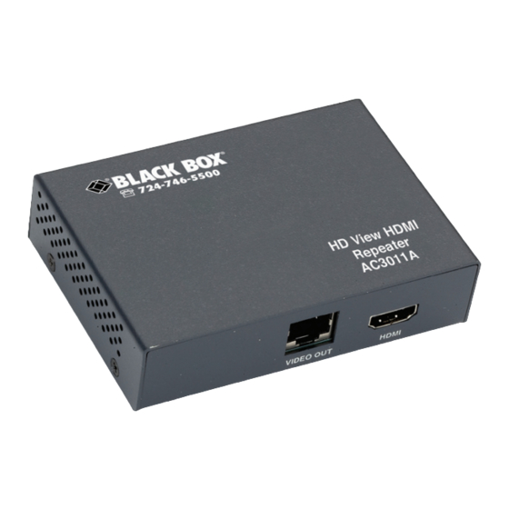
HD View HDMI 2.6 Repeater (AC3011A) 2.6.1 Repeater’s Side 1 Figure 2-5 illustrates the repeater’s side 1. Table 2-5 describes its components. Figure 2-5. Repeater, side 1. Table 2-5. Components on repeater’s side 1. Component Description RJ-45 connector Video in RJ-45 connector Barrel connector 5-VDC power... -
Page 15: Side 2
Chapter 2: Overview 2.6.2 Repeater’s Side 2 Figure 2-6 shows the repeater’s side 2. Table 2-6 describes its components. Figure 2-6. Repeater side 2. Table 2-6. Components on repeater’s side 2. Component Description RJ-45 connector Video out HDMI connector HDMI Page 13 724-746-5500 | blackbox.com... -
Page 16: Compatible Cabling
2.7 Compatible Cabling HD View HDMI works with CAT5/5e/6/7 data cabling. Some skew-free CAT5 cabling is specific to a particular vendor and is not compatible with Black Box products. Because of the manufacturing methods, CAT6 cable can exhibit greater skew than standard CAT5/5e and may require skew compensation beyond what the HD View HDMI offers. -
Page 17: Configuration And Installation
Chapter 3: Configuration and Installation 3. Configuration and Installation 3.1 Pre-Installation Guidelines Make sure that the player and the screens are compatible. Check that they work together before connecting the HD View HDMI system. 3.2 Configuration Figure 3-1 illustrates a DVI extension. You can connect one side (either player or screen) to the system with an HDMI connector with the other side (screen or play- er) connected with a DVI connector. - Page 18 HD View HDMI Figures 3-2 and 3-3 illustrate HDMI extensions. Player Video out Plasma/LCD HDMI cable screen, video plus audio Transmitter Video CAT5 cable, up to 197 feet (60 m) HDMI cable Video in Receiver Figure 3-2. HDMI: Video plus audio transmission. Page 16 724-746-5500 | blackbox.com...
- Page 19 Chapter 3: Configuration and Installation Player Video out Plasma/LCD HDMI cable screen, video plus audio Transmitter Video CAT5 cable, up to 197 feet (60 m) DDC cable HDMI cable Video in Receiver Figure 3-3. HDMI: Video plus audio transmission plus HDCP, CEC support. Page 17 724-746-5500 | blackbox.com...
-
Page 20: Connecting The Hd View Hdmi System
HD View HDMI 3.3 Connecting the HD View HDMI system Connect the Video CAT5 cable as follows: Connect a CAT5 cable up to 192 feet (60 m) to the VIDEO OUT port of the Transmitter and the VIDEO IN port of the Receiver. See Figures 3-4 and 3-5. HDMI connector player... -
Page 21: Connecting The Player And Screen
Chapter 3: Configuration and Installation 3.4 Connecting the Player and Screen The HD View HDMI can be used to connect players and screens of HDMI to DVI ports, by using standard HDMI to DVI cables/adapters. HDMI players can be con- nected to DVI screens and vice versa. -
Page 22: Storing The Screen's Ddc
HD View HDMI 3.5.1 Storing the Screen’s DDC To store the screen’s DDC, connect a CAT5 cable between the DDC ports of the Transmitter and Receiver. The position of the STORED/SCREEN selector switch position is not relevant. NOTE: There is no need to connect: •... -
Page 23: Connecting To The Power Supply
NOTE: When cascading eight levels, use CAT6 UTP cable. The total distance should be 640 feet (200 m). HDMI HDMI Player HDMI to HDMI cable DVI cable HDMI cable Receiver (AC3010A) HD-HDMI HD-HDMI Transmitter Repeater Repeater (AC3010A) (AC3011A) (AC3011A) CAT6 cable... -
Page 24: Troubleshooting
4.2 Calling Black Box If you determine that your HD View HDMI is malfunctioning, do not attempt to alter or repair the unit. It contains no user-serviceable parts. Contact Black Box Technical Support at 724-746-5500. Before you do, make a record of the history of the problem. We will be able to... -
Page 25: Shipping And Packaging
• Package it carefully. We recommend that you use the original container. • If you are returning the unit, make sure you include everything you received with it. Before you ship for return or repair, contact Black Box to get a Return Authorization (RA) number.