Table of Contents
Advertisement
Advertisement
Table of Contents

Related Manuals for Saga SAGA1-L Series

Summary of Contents for Saga SAGA1-L Series
- Page 1 INSTALLATION & OPERATION MANUAL...
-
Page 2: Table Of Contents
SAGA1-L Series SAGA 1-L10/L12 User’s Manual Table Of Contents Chapter 1 Warranty 1-1 Warranty 1-2 Warranty Period 1-3 Excluded Items 1-4 Remarks Chapter 2 Operating Precautions 2-1 Attention 2-2 Precautions 2-3 Emergency Procedures Chapter 3 Standard Accessories Chapter 4 Operation... -
Page 3: Chapter 1 Warranty
SAGA1-L Series Chapter 1 Warranty 1 - 1 Warranty Gain Electronic Co., Ltd. guarantees that this equipment meets its published it should work as expected. However, GAIN does not guarantee that operation in SAGA1 system is error free or without intermission. -
Page 4: Chapter 2 Operating Precautions
SAGA1-L Series Chapter 2 Operating Precautions 2 - 1 Attention Read this manual carefully before operating and installing SAGA1-L10/L12. Due to the complex nature of equipment, it is necessary to read the entire manual before installation. Never allow any unauthorized personnel to dismantle equipment as this may cause the equipment to be damaged. -
Page 5: Emergency Procedures
SAGA1-L Series SAGA is suitable for use in diverse industrial environments correct operating and maintenance will extend the SAGA1 system’s life. Check EMS mushroom and the other security functions of the SAGA1 system before daily operation. Presses EMS mushroom when malfunctions or abnormal conditions occur. -
Page 6: Chapter 3 Standard Accessories
SAGA1-L Series Chapter 3 Standard Accessories A standard and full set of SAGA1-L10/L12 is consist of: SAGA1-L10 Transmitter ( strap included ) - 1 unit Receiver - 1 unit SAGA1-L12 Transmitter ( strap included ) - 1 unit Receiver - 1 unit... -
Page 7: Chapter 4 Operation
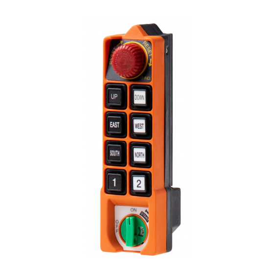
SAGA1-L Series Chapter 4 Operation 4 – 1 Transmitter Configuration SAGA1-L10 SAGA1-L12 Figure 4-1 Transmitter Configuration 1- Antenna 6- F1 Pushbutton 2- Emergency Stop 7- Start Pushbutton 3- LED Indicator 8- Battery Cover 4- Motion Pushbutton 9- Rotary Key Switch 5- Aux. -
Page 8: General Operation
SAGA1-L Series 4 – 2 General Operation Install 2 new AA-size alkaline batteries in the battery box of SAGA1-L12, then insert into battery case of transmitter; or battery chamber of SAGA1- L10, and screw up transmitter’s bottom cover. Make sure the “+” and “-”... -
Page 9: The Use Of Copier
SAGA1-L Series automatically after been released). 4-3-2 Acceleration Operation 1. For SAGA1-L12 : “Start” pushbutton is the acceleration pushbutton. 2. For SAGA1-L10 : “Start” key is the acceleration key to use. 3. When a motion is in the second speed, quick touch of acceleration pushbutton will accelerate the speed. -
Page 10: Change Of Frequency
SAGA1-L Series 4 – 5 Change of Frequency It is easy to change frequency of the SAGA1-L series simply by replacing correspondent frequency crystal in both the TX and RX. Note: To replace a new crystal, please note that there are two kinds of frequencies (VHF and UHF) available. -
Page 11: Id-Code Remote Setting
SAGA1-L Series 4 – 6 ID-Code Remote Setting ID-Code remote setting allows you to pair the new TX or RX if one of them is damaged. Using ID-Code remote setting will make both the TX and RX to have the same ID-Code. -
Page 12: Receiver Voltage Selection
SAGA1-L Series 4 – 7 Receiver Voltage Selection There are two types of power voltages (DC and AC) available for the SAGA1-L series: (1) DC Type: Input Voltage : 12~24 VDC Relay Contact: 10A-36VDC 2) AC Type Three different AC transformers: 48/110/220V, 48/220/380V, 110/220/380V. -
Page 13: Function Setting (Defined By Customer)
SAGA1-L Series APPENDIX I Function Setting (Defined by Customer) 1. Pushbutton Function setting: 1-1.“UP/DOWN”, ”EAST/WEST”, ”SOUTH/NORTH”, ”R1/R2”, ”R3/R4” Pushbutton Function Setting: Item Title Content Description Button 1.Normal/Normal Normal: The relative relay is “on” when the Function 2.Toggle/Toggle pushbutton is pressed and held, on the other 3.No/Off... - Page 14 SAGA1-L Series 1. Ctrl. by EMS Control by EMS: means the corresponding Control 2. Bypass EMS relay of function pushbutton is controlled by EMS mushroom or emergency stop signal. Bypass EMS: means the corresponding relay of function pushbutton will not be controlled by EMS mushroom or emergency stop signal.
- Page 15 SAGA1-L Series 2. Transmitter Function Setting: Item Title Content Description Power-On 1. Any Pushbutton Any Pushbutton: When mushroom is released Mode 2. Start Pushbutton and security or rotary key is at “on” position, the receiver will be “Power-On” by pressing any pushbutton on transmitter.
- Page 16 SAGA1-L Series Remote 1. Enable Enable: Allow the transmitter to do ID-Code Setting 2. Disable remote setting. Disable: Not allow ID-Code remote setting on transmitter. 3. Receiver Function Setting: Item Title Content Description Passive Act 1. Relay-off Passive Act: The function of this item is used to 2.
-
Page 17: Correspondence Between Pushbuttons And Relay Output
SAGA1-L Series APPENDIX II Correspondence Between Pushbutton and Relay Output All SAGA1-L12 is equipped with 4 relays in each group of motions, such as Up/Down, East/West, South/North, R1/R2, R3/R4; however SAGA1-L10 only Up/Down is with 4 relays, others with 3. Their corresponding relation is shown as below:... - Page 18 SAGA1-L Series 6.Dual Motor(2)/Dual Motor(2) Step Step Step Step Note: When pushbutton is released from 2 speed and back to 1 one, the 1 speed relay is not activated but bypassed to nothing. 7.3 Speed Acce./3 Speed Acce. Step Step...
- Page 19 SAGA1-L Series APPENDIX III PC Software Installation and Operation Guide 1. Software Installation: 1-1. Open CD-Rom of your computer and insert SAGA1-L10/L12 PC software CD, the program will run automatically. Click “Install” to proceed installing, “Cancel” to exit. 1-2. Click “Next” when the screen shows as below.
- Page 20 SAGA1-L Series 1-3. Click “Finish” to end the installation, then remove the CD from the CD-Rom. The program will add a shortcut on your desktop. 2. Software Operation and Function Setting: 2-1. To activate the program, either double click on the desktop shortcut for SAGA1- L10/L12 software, or from the “start”...
- Page 21 SAGA1-L Series 2-2. Default and second page of the program: Open File Save File Print COM Port Setting Switch to 2 Page Click here to exit the program Default Page: Function Setting Second Page: Customer Info.
- Page 22 SAGA1-L Series 2-3. Using RS232 connecting cable to connect transmitter or receiver to the computer, click “Read Data” to retrieve the setting, then click “OK” to see the result. 2-4. After changing the function setting (refer to Appendix I & II), either to save the setting data to computer hard disk or write it to another transmitter or receiver.
- Page 23 SAGA1-L Series 2-5. To read data from saved file, click “Open File”, after the source file (*.saga) chosen, click “Open”, then “OK”. 2-6. Second page (Customer Info.) of the program is to store the customers basic information and their setting data, convenient for file sorting and further service, such as to make copy of their lost or malfunction transmitter, also to diagnose their problem from your office.
- Page 24 SAGA1-L Series APPENDIX IV Additional Applications 1.Exchangeable NC/NO Relays: There are reserved NC/NO output contacts for an easy exchange of NC or NO relays (The default is NO relay), depending on the customer’s need. For SAGA1-L10, R0/R1/R2 can be changed for either NC or NO relays.
- Page 25 SAGA1-L Series APPENDIX V General Specification Frequency Range: 433.05~434.79 MHz ID Code: 32 Bits Channel Space: 250 KHz Hamming Distance: >4 Housing Material: Reinforced Plastic and Glass Fiber Protection Class: IP65 Operating Temp.: -40℃ ~ +80℃ Maximum Operating Range: Up to 100 Meters...