Table of Contents
Advertisement
Quick Links
Honeywell
APPLICATION
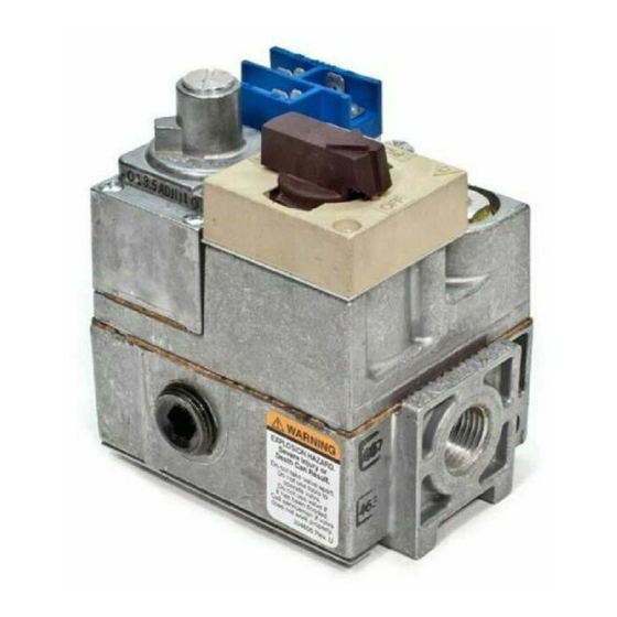
V400 and V800 are used on gas fired standing pilot
appliances with 30 mV thermocouple. These gas controls
include a manual gas valve, safety shutoff, single millivolt-
age automatic operator, and pressure regulator, pilot gas
filter and flow adjustment, pressure tapping, and thermo-
couple connector.
V400 is used on 120V systems. V800 is used on 24V
systems. Refer to Table 1 for more specifications. Refer to
Table 2 for available gas capacities.
V800 gas controls are available with 1/4 x 1/4 inch or 3/
16 x 1/4 inch energy cut-off (ECO) quick-connects. With the
connector, an ECO high limit can be connected into the
power circuit. When the temperature at the ECO exceeds
the high limit, a switch opens and de-energizes the power
MODEL NUMBER
SUFFIX LETTER
A
C
M
P
PIPE SIZE
(INLET x
OUTLET)
1/2" x 3/8"
1/2" x 1/2"
1/2" x 3/4"
3/4" x 3/4"
a
Capacity is based on 1000 Btu/ft
gravity natural gas at 0.25 kPa pressure drop]. Use conversion factors to convert to other gases.
TYPE OF GAS
Manufactured
Mixed
Propane
INSTALLATION
WHEN INSTALLING THIS PRODUCT...
1. Read these instructions carefully. Failure to follow
them could damage the product or cause a hazardous
condition.
2. Check the ratings given in these instructions and on
the product to ensure the product is suitable for your
application.
J.A.
Rev. 6-91
TABLE 1—MODEL SPECIFICATIONS.
AMBIENT
TEMPERATURE RANGE
32° F to 175° F
[0° C to 79° C]
32° F to 175° F
[0° C to 79° C]
-40° F to 175° F
[-40° C to 79° C]
-40° F to 175° F
[-40° C to 79° C]
TABLE 2—GAS CONTROL CAPACITIES.
GAS CONTROL
a
CAPACITY
AT
1 INCH WCPD
3
3
ft
/hr
m
/hr
110
3.1
225
6.4
250
7.1
335
9.5
3
, 0.64 specific gravity natural gas at 1 inch wc pressure drop [37.3 MJ/m
SPECIFIC GRAVITY
0.60
0.70
1.53
COMBINATION GAS CONTROLS
unit and shuts off main burner and pilot gas flow. To restart
system, pilot flame must be relit and gas control must be
reset manually.
Power for the gas control and the control system is
provided by a 30 mV thermocouple. We recommend the
Q340 Thermocouple.
Replacement parts:
1. Energy cut off (ECO) connector: 392451-1
2. Pressure Regulators:
Standard opening pressure regulator: V5306A,B.
Step opening pressure regulator: V5307A,B.
3. Valve Operators:
Line Voltage Operator: V404B.
Low Voltage Operator: V804B.
PRESSURE
REGULATOR TYPE
Standard-Opening
Step-Opening
Standard-Opening
Step-Opening
MAXIMUM
REGULATION
CAPACITY
3
3
ft
/hr
m
/hr
110
3.1
225
6.4
290
8.2
425
12.0
MULTIPLY LISTED CAPACITY BY:
0.516
0.765
1.62
3. Ensure installer is a trained, experienced service
technician.
4. After completing installation, use these instructions to
check product operation.
V400 AND V800
PRESSURE
REGULATOR MODEL
V5306A
V5307A
V5306B
V5307B
MINIMUM
REGULATION
CAPACITY
3
ft
/hr
11
23
23
34
Form Number 95-6996—10
©Honeywell Inc. 1991
3
m
/hr
0.3
0.7
0.7
1.0
3
, 0.64 specific
Advertisement
Table of Contents

Related Manuals for Honeywell V400


Summary of Contents for Honeywell V400
- Page 1 Replacement parts: couple connector. 1. Energy cut off (ECO) connector: 392451-1 V400 is used on 120V systems. V800 is used on 24V 2. Pressure Regulators: systems. Refer to Table 1 for more specifications. Refer to Standard opening pressure regulator: V5306A,B.
- Page 2 control. 3. Install sediment trap in gas supply line. Refer to Fig. 1. WARNING INSTALL CONTROL 1. This control can be mounted 0-90 degrees, in any FIRE OR EXPLOSION HAZARD direction, from the upright position of the gas control knob, CAN CAUSE PROPERTY DAMAGE, SEVERE IN- including vertically.
- Page 3 3. Unscrew brass compression fitting from pilot gas outlet. Refer to Fig. 4. Slip fitting over tubing and slide out TWO IMPERFECT GAS CONTROL THREADS of way. NOTE: When replacing a control, cut off old compression PIPE fitting and replace with new compression fitting provided on new combination gas control.
- Page 4 Bubbles indicate gas leak. 2. If leak is detected, tighten pipe connections. Fig. 5—Typical V400 wiring diagram. 3. Stand clear while lighting main burner to prevent injury caused from hidden leaks which could cause flashback in Wiring V800 models the appliance vestibule.
- Page 5 V5306A,B Standard-Pressure Regulator crease or counterclockwise to increase pilot flame. 1. Check the manifold pressure listed on the appliance 3. Always replace cover screw after adjustment and nameplate. Gas control outlet pressure should match the tighten firmly to ensure proper operation. nameplate.
- Page 6 TABLE 7—PRESSURE REGULATOR SPECIFICATION PRESSURES IN kPa. OUTLET PRESSURE NOMINAL SETTING TYPE NOMINAL INLET FACTORY SETTING RANGE MODEL OF GAS PRESSURE RANGE Step Full Rate Step Full Rate NATURAL 1.2-1.7 — — 0.7-1.2 2.9-3.9 — — NATURAL 1.2-1.7 None 0.7-1.2 2.9-3.9 None CHECK SAFETY SHUTDOWN PERFORMANCE...
- Page 7 LIGHTING THE PILOT BURNER 9. Push in gas control knob all the way and hold in. Immediately light the pilot flame with a match and continue STOP: READ THE WARNINGS ABOVE. holding the gas control knob in for one minute after the pilot flame is lit.
- Page 8 Honeywell Inc. International Sales Offices in all principal cities of the world. Manufacturing in U.S.A.: 1885 Douglas Drive N. Australia, Canada, Finland, France, Germany, Japan, Mexico, Netherlands, Golden Valley, MN 55422-4386 Spain, Taiwan, United Kingdom, U.S.A. CANADA: 740 Ellesmere Road...