
Related Manuals for Kenmore PG-40406S0L


Summary of Contents for Kenmore PG-40406S0L
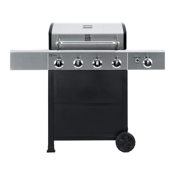
- Page 1 Use & Care Guide Manual de Uso y Cuidado English / Español Kenmore ® Liquid Propane Gas Grill Parrilla a gas de propane liquido Model/Modélo: PG-40406S0L P/N 40600050A ®...
-
Page 2: Installation Safety Precautions
Installation Safety Precautions DANGER • Please read this User’s Manual in its entirety before using the grill. • Failure to follow the provided instruction can result in If you smell gas: seriously bodily injury and/or property damage. • Some parts of this grill may have sharp edges. Please wear suitable protective gloves. -
Page 3: Table Of Contents
This product contains chemicals, including lead and lead Safety Symbols ..2 compounds in brass fittings. It also produces combustion Kenmore Grill Warranty ..4 by-products when used. These substances are known to Use and Care . . . - Page 4 KENMORE LIMITED WARRANTY WITH PROOF OF SALE: the following warranty coverage applies when this appliance is correctly installed, operated and maintained according to all supplied instructions. Note: Consumer is responsible for Shipping & handling of all warranty replacement parts. FOR ONE YEAR: from the date of sale this grill is warranted against defects in material or workmanship, consumer will receive free replacement parts with proof of purchase, consumer is responsible for S&H cost.
-
Page 5: Use And Care
LP Cylinder USE AND CARE • The LP cylinder used with your grill must meet the following requirements: DANGER • Use LP cylinders only with these required measurements: 12" (30.5cm) (diameter) x 18" (45.7 cm) (tall) with 20 lb. (9 kg.) Capacity maximum. - Page 6 LP Tank Exchange Connecting Regulator To The LP Tank • Many retailers that sell grills offer you the option of replacing 1. LP tank must be properly secured onto grill. (Refer to your empty LP tank through an exchange service. Use only those assembly section.) reputable exchange companies that inspect, precision fill, test 2.
- Page 7 Leak Testing Valves, Hose and Regulator 1. Turn all grill control knobs to OFF. 2. Be sure regulator is tightly connected to LP tank. 3. Completely open LP tank valve by turning OPD hand wheel counterclockwise. If you hear a rushing sound, turn gas off immediately.
- Page 8 Safety Tips WARNING ▲ Before opening LP cylinder valve, check the coupling nut for tightness. ▲ When grill is not in use, turn off all control knobs and LP cylinder For Safe Use of Your Grill and to Avoid Serious valve.
- Page 9 Burner Flame Check WARNING • Remove cooking grates and heat diffusers. Light burners, turn knobs from HI to LO. You should see a smaller flame in LO position than seen on HI. Perform burner flame check Turn controls and gas source or tank OFF when not on sideburner, also.
- Page 10 • Painted surfaces: Wash with mild detergent or nonabrasive Storing Your Grill cleaner and warm soapy water. Wipe dry with a soft nonabrasive cloth. •Clean cooking grates. • Stainless steel surfaces: To maintain your grill’s high quality appearance, wash with mild detergent and warm soapy water •Store in dry location.
- Page 11 Food Safety Food safety is a very important part of enjoying the outdoor cooking experience. To keep food safe from harmful bacteria, follow these four basic steps: Clean: Wash hands, utensils, and surfaces with hot soapy water before and after handling raw meat and poultry. Separate: Separate raw meats and poultry from ready-to-eat foods to avoid cross contamination.
-
Page 12: Parts List
PARTS LIST PARTS LIST Description Part Number Description Part Number Description Side Burner Lid 40800065 Bottom Shelf 52200073 HEAT DIFFUSERS Side Burner Grid 40800119 Front Panel 40600062 COOKING GRATE Rotate Rod, Side Burner Lid 40800118 Side Lower Rail 52200064 SWING AWAY GRATE Side Burner Base 52200052 Side Upper Rail... -
Page 13: Parts Diagram
PARTS DIAGRAM... -
Page 14: Before Assembly
BEFORE ASSEMBLY NOTICE: Once you have unpacked the grill according to the STOP SHEET instructions, check all grill parts against the pictures on this and the following two pages. If any parts are missing or damaged, call 1-888-287-0735, M – F 8:00 –... - Page 15 BEFORE ASSEMBLY...
-
Page 16: Assembly
BEFORE ASSEMBLY... -
Page 17: Assembly
ASSEMBLY CAREFULLY READ AND PERFORM ALL ASSEMBLY INSTRUCTIONS ON THE FOLLOWING PAGES. Tools Required: Adjustable wrench (not provided) Screwdriver (not provided) 7/16” Combination wrench (not provided) The following hardware is provided in blister pack for convenient use. M4X10 screw AA Battery Qty: 54 pcs Qty: 1 pc M5X10 screw... - Page 18 Left Frame Install (4)M4×10 Screws as shown to the leg marked “5A”. Do not fully tighten the screws at this □ time. Leave 1/8-inch gap below screw head for rail attachment. (A) □ Attach one end of a Side Upper Rail “6A” to the leg, tighten the screws and install and tighten another (1)M4×10 Screw.(C) □...
- Page 19 Right Frame □ Install (4)M4×10 Screws as shown to the leg marked “5C”. Do not fully tighten the screws at this time. Leave 1/8-inch gap below screw head for rail attachment. (A) □ Attach one end of a Side Upper Rail “6A” to the leg, tighten the screws and install and tighten another (1)M4×10 Screw.(C) □...
- Page 20 Bottom Shelf Install (4)M4×10 Screws as shown to Right Frame. Do not fully tighten the screws at this time. □ Leave 1/8-inch gap below screw head for panel attachment. (A) □ Install (4) M4X10 screws as shown to Left Frame. Do not fully tighten screws at this time. Leave 1/8-inch gap below screw head for panel attachment.
- Page 21 Front Panel Attach the two front panel sections together into a single front panel with (1) M4X10 screw as shown. □ □ Attach the front panel to the cart by slipping the four panel holes on each side over and down onto the four protruding screw heads on the left and right frames.
- Page 22 Wheels to Cart □ Turn cart upside down and attach Legs to Bottom Shelf with (4) M6X13 screws as shown. (A) □ Tap both Leg Extenders onto Left Legs. (B) □ Remove hitch pin, nut and washer from axle rod. Insert axle rod through Wheels and Right Leg Frame. Reattach washer, nut and hitch pin.
-
Page 23: Side Burner
Grill Head to Cart □ This step requires two people to lift and position grill head onto cart. Remove the tie wraps and packaging material from regulator hose, side burner valve and igniter □ wire. Pull hose and igniter wire out to side of grill head. Carefully lower the grill head onto the cart. - Page 24 Left Side Shelf □ Attach fascia to left side shelf with (2) M5x10 screws and M5 flat washers. (A) □ Attach Side Shelf Support Angle Bar with (4) M4x10 screws.(B) □ Align the Side Fascia and Control Panel. □ Attach shelf to firebox as follows: - From inside to outside of firebox with (2) M6x13 screws and M6 compression washers.
-
Page 25: Right Side Shelf
NOTES Right Side Shelf Remove side burner grate from side burner before assembling and attaching the right side shelf, □ □ Attach fascia to right side shelf with (2) M5x10 screws and M5 flat washers.(A) □ Attach Side Shelf Support Angle Bar with (4) M4x10 screws.(B) □... -
Page 26: Control Knob
Side burner □ Loosen side burner in side shelf. (B ). To loosen, unscrew and remove two front screws and washers holding sideburner in place. (A). Note: Do not loosen electrode screw. □ Remove the 2 pre-installed screws from the valve stem and set them aside. (C) □... - Page 27 Heat Diffusers, Cooking Grates and Warming Rack □ Place Heat Diffusers over burners. Diffusers will fit in firebox in either direction. □ Place Cooking Grates onto grate rests at front and rear of Firebox. □ Insert warming rack into brackets at top of Firebox with Curved edge to front as shown.
- Page 28 Drip Tray, Drip Cup and LP Tank Attach Back Rail to the Cart and Grill Head with (4)M4×10 Screws as shown.(A) □ □ Remove the cotter key and retention pin from the hose bracket on cart right leg. Insert hose into bracket and replace cotter and pin.
-
Page 29: Regulator
EMERGENCIES: If a gas leak cannot be stopped, or a fire occurs due to gas leakage, call the fire department. •Turn off gas at LP cylinder or at source on natural gas systems. If the Gas leaking from • Damaged hose. hose is cracked or cut but not burned, simply replace valve / hose / cracked/cut/burned hose. - Page 30 Troubleshooting (continued) Problem Possible Cause Prevention/Solution Burner(s) will not light ELECTRONIC IGNITION: • See Section I of Electronic Ignition System. • No spark, no ignition noise. using ignitor. (See Electronic Ignition • See Section II of Electronic Ignition System. Troubleshooting also) •...
- Page 31 Troubleshooting - Electronic Ignition Problem (Ignition) Possible Cause Preventio SECTION I • Check battery orientation. • Install battery (make sure that “+” and “-” No sparks appear at • Battery not installed connectors are oriented correctly, with “+” end up any electrodes when properly.
- Page 32 Precauciones de instalación PELIGRO • Por favor lea este Manual del usuario en su totalidad antes de usar la parrilla. • El incumplimiento de la instrucción proporcionada puede Si siente olor a gas: resultar en lesiones graves o daños a la propiedad. 1.
- Page 33 Medidas de seguridad para la instalación . . . estado de California causan cáncer, defectos congénitos . .34 Garantía para la parrilla Kenmore . . . y otros daños reproductivos..35-41 Uso y mantenimiento . . .
- Page 34 GARANTÍ A LIMITADA DE KENMORE CON PRUEBA DE VENTA: la siguiente cobertura de garantí a se aplica cuando este electrodoméstico se instala, opera y mantiene correctamente de acuerdo con todas las instrucciones provistas. Nota: El consumidor es responsable del enví o y manejo de todas las piezas de repuesto bajo garantí...
- Page 35 UOS Y MANTENIMIENTO Tanque de gas propano • El cilindro de gas LP con la parrilla debe cumplir los siguientes requisitos: • Utilice cilindros de propano licuado solo con estas medidas requiere: 12"(30,5 cm) (diámetro) x 18" (45.7 cm) (alto) con 20 •...
- Page 36 Cambio del tanque de gas Como conectar el regulador al tanque de gas propano • Muchos comerciantes minoristas que venden parrillas, le 1. El tanque del LP se debe asegurar correctamente sobre parrilla. ofrecen la opción de cambiar su tanque de gas vacío (Refiera a la sección de la asamblea.) mediante un servicio de recambio.
- Page 37 Prueba para detectar fugas de las válvulas, las mangueras y el regulador 1. Gire todas las perillas de control de la parrilla a la posición deAPAGADO. 2. Cerciórese de que el regulador esté bien conectado al tanque de gas. 3. Abra por completo la válvula del tanque, girando la manilla en sonido sentido contrario a las agujas del reloj.
- Page 38 Consejos de seguridad ADVERTENCIA ▲ Verifique que la tuerca de unión esté bien apretada antes de abrir la válvula del tanque de gas. ▲ Cuando no use la parrilla, cierre todas las perillas de control Para usar su parrilla en forma segura y para evitar y la válvula del tanque de gas.
- Page 39 Control de la llama del quemador • Retire las parrillas de cocción y los reguladores de llama. Encienda los quemadores aduación ALTA (HI) a la graduación BAJA (LO). Deberá ver ADVERTENCIA una llama más reducida en la graduacaduación alta. Controle siempre las llamas antes de cada uso.
- Page 40 • Piezas plásticas: Lávelas con agua jabonosa tibia y séquelascon un paño Cómo guardar su parrilla • Superficies de porcelana: Debido a su composición vítrea, la mayoría de los residuos se puede eliminar con un paño • Limpie las parrillas de cocción. empapado en una solución de bicarbonato de soda y agua, o •...
- Page 41 Cocción: Cocine bien las carnes y las piezas de ave, para matar las bacterias. Use un termómetro para verificar que los alimentos alcancen la temperatura interna adecuada. Limpio: Lave las manos, los utensilios, y las superficies con agua jabonosa caliente antes y después que maneja la carne y aves de corral crudas.
-
Page 42: Not Pictured
LISTA DE PARTES Part Part Description Description Number Number Tapa del quemador lateral Estante inferior 40800065 52200073 Rejilla del quemador lateral Panel frontal 40800119 40600062 Rodar la varilla, tapa lateral de la Carril inferior lateral 40800118 52200064 hornilla Base del quemador lateral Carril superior lateral 52200052 52200061... - Page 43 DIAGRAM...
- Page 44 BEFORE ASSEMBLY AVISO: Una vez que usted haya desempaquetado la parrilla según las instrucciones de la HOJA de la PARADA, compruebe todas las piezas de la parrilla contra los cuadros en esto y las dos páginas siguientes. Si usted parte es que falta o dañado, la llamada 1-888-287-0735.
- Page 45 BEFORE ASSEMBLY...
- Page 46 BEFORE ASSEMBLY...
- Page 47 ASSEMBLY LEA Y REALICE CUIDADOSAMENTE TODAS LAS INSTRUCCIONES DE ASAMBLEA EN LAS PÁGINAS SIGUIENTES. Las herramientas requirieron: El destornillador de la llave ajustable no proporcionada no proporcionado 7/16” la llave combinada (no proporcionada) el hardware siguiente se proporciona en el paquete de ampolla para el uso conveniente. M4X10 tornillo AA Batería Qty: 54 pcs...
- Page 48 Marco izquierdo □ Instale (4) M4 × 10 Tornillos como se muestra en la pata marcada "5A". No apriete completamente los tornillos en este momento. Deje un hueco de 1/8 pulgada debajo de la cabeza del tornillo para fijar el riel.
- Page 49 Marco derecho □ Instale (4) M4 × 10 Tornillos como se muestra en la pata marcada "5C". No apriete completamente los tornillos en este momento. Deje un hueco de 1/8 pulgada debajo de la cabeza del tornillo para fijar el riel. (A) □...
- Page 50 Estante inferior □ Instale (4) tornillos M4 × 10 como se muestra en el marco derecho. No apriete completamente los tornillos en este momento. Deje un hueco de 1/8 pulgada debajo de la cabeza del tornillo para fijar el panel. (A) □...
- Page 51 Panel frontal □ Fije las dos secciones del panel frontal en un único panel frontal con (1) tornillo M4X10 como se muestra. □ Fije el panel frontal al carro deslizando los cuatro orificios del panel de cada lado hacia arriba y hacia abajo sobre las cuatro cabezas de tornillo que sobresalen en los marcos izquierdo y derecho.
- Page 52 Ruedas al carrito □ Coloque el carro boca abajo y coloque las patas en la plataforma inferior con (4) tornillos M6X13 como se muestra. (A) □ Toque ambos Extensores de Pierna en las Piernas Izquierdas. (B) □ Retire el pasador de enganche, la tuerca y la arandela de la varilla del eje. Inserte la barra del eje a través de las ruedas y el marco de la pierna derecha.
- Page 53 Grill Head to Cart □ Este paso requiere dos personas para levantar y colocar la cabeza de la parrilla en el carro. □ Retire las abrazaderas y el material de embalaje de la manguera del regulador, la válvula del quemador lateral y el cable del encendedor. Tire de la manguera y el cable del encendedor hacia afuera al lado de la cabeza de la parrilla.
- Page 54 Estantería lateral izquierda □ Fijar el tablero al estante izquierdo con (2) tornillos M5x10 y arandelas planas M5. (A) □ Fije la barra de ángulo de soporte del estante lateral con (4) tornillos M4x10 (B) □ Alinee la Faja lateral y el Panel de control. □...
- Page 55 NOTES Estantería lateral derecha □ Retire la rejilla del quemador lateral del quemador lateral antes de montar y colocar el estante lateral derecho, □ Fijar el tablero en el estante del lado derecho con (2) tornillos M5x10 y arandelas planas M5. (A) □...
- Page 56 Quemador lateral □ Afloje el quemador lateral en el estante lateral. (B). Para aflojar, desenrosque y quite los dos tornillos delanteros y las arandelas que sostienen el quemador lateral en su lugar. (UN). Nota: No afloje el tornillo del electrodo. □...
- Page 57 Difusores de calor, rejillas de cocción y estante de calentamiento □ Coloque los difusores de calor sobre los quemadores. Los difusores encajarán en la cámara de combustión en cualquier dirección. Coloque las rejillas de cocción sobre las rejillas de la parrilla delantera y trasera de la caja de combustión.
- Page 58 Bandeja de goteo, Copa de goteo y tanque de LP □ Fije el riel trasero al carro y la cabeza de la parrilla con (4) tornillos M4 × 10 como se muestra (A) □ Retire la chaveta y el pasador de retención del soporte de la manguera en la pata derecha del carro.
-
Page 59: Troubleshooting
EMERGENCIES: If a gas leak cannot be stopped, or a fire occurs due to gas leakage, call the fire department. •Turn off gas at LP cylinder or at source on natural gas systems. If the Gas leaking from • Damaged hose. hose is cracked or cut but not burned, simply replace valve / hose / cracked/cut/burned hose. - Page 60 Troubleshooting (continued) Problem Possible Cause Prevention/Solution Burner(s) will not light ELECTRONIC IGNITION: • See Section I of Electronic Ignition System. • No spark, no ignition noise. using ignitor. (See Electronic Ignition • See Section II of Electronic Ignition System. Troubleshooting also) •...
- Page 61 Troubleshooting - Electronic Ignition Problem (Ignition) Possible Cause Preventio SECTION I • Check battery orientation. • Install battery (make sure that “+” and “-” No sparks appear at • Battery not installed connectors are oriented correctly, with “+” end up any electrodes when properly.