Fujitsu AGU9RLF Installation Manual
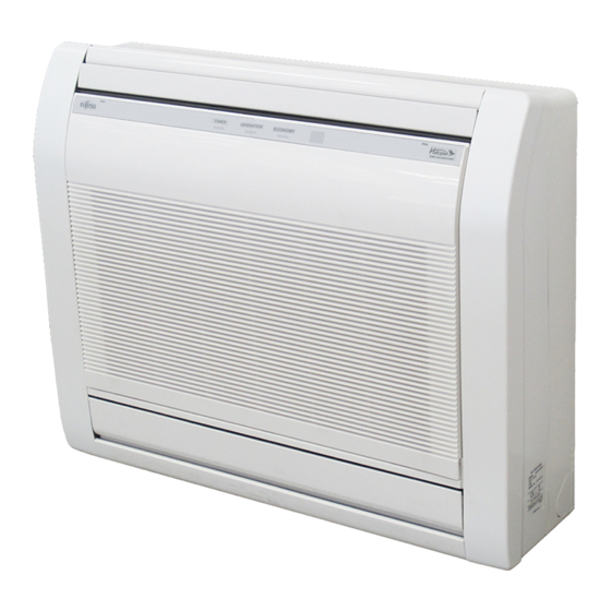
Indoor unit (floor type)
Hide thumbs
Also See for AGU9RLF:
- Design & technical manual (51 pages) ,
- Operating manual (19 pages) ,
- Service instruction (105 pages)
Table of Contents
Advertisement
Advertisement
Table of Contents

Related Manuals for Fujitsu AGU9RLF


Summary of Contents for Fujitsu AGU9RLF
- Page 1 AIR CONDITIONER INSTALLATION MANUAL INDOOR UNIT (Floor Type) For authorized service personnel only. MANUEL D’INSTALLATION UNITÉ INTÉRIEURE (type sol) Pour le personnel agréé uniquement. MANUAL DE INSTALACIÓN UNIDAD DE INTERIOR (tipo de piso) Solo para personal autorizado. PART No. 9378533059...
-
Page 2: Table Of Contents
When Installing... PART No.9378533059 ...In a Ceiling or Wall Contents Make sure the ceiling/wall is strong enough to hold the unit’s weight. It may be necessary to construct a strong wood or metal frame to provide added support SAFETY PRECAUTIONS .................... 2 ...In a Room ABOUT THE UNIT ....................... -
Page 3: General Specification
Name and Shape Q’ty Name and Shape Q’ty 2.2. Special tools for R410A Remote Tapping screw controller (M3 × 12 mm) Tool name Contents of change Pressure is high and cannot be measured with a conven- tional (R22) gauge. To prevent erroneous mixing of other Gauge manifold refrigerants, the diameter of each port has been changed. -
Page 4: Electrical Requirement
EMBEDDING THE INDOOR UNIT IN A WALL 4. ELECTRICAL REQUIREMENT • When installing a grating, use a grating with narrow upper and lower horizontal bars so that the airfl ow from the upper and lower air outlets does not contact the bars. If the The indoor unit is powered from the outdoor unit or branch box. - Page 5 The side panel L, R installation For RIGHT or LEFT piping (1) Firstly, fi t the top part of the side panel, and insert top and bottom hooks. Unit: mm (in.) (2) 4 screws is attached. (3) The intake grille is attached. Mounting shaft Front panel Front panel...
- Page 6 The drain hose can be connected at either side of the indoor unit. WARNING The unit has been shipped with the drain hose connected at left (viewed from the back of the unit) and the drain cap applied at right. Fix the indoor unit with 4 screws surely.
-
Page 7: Electrical Wiring
When using conventional fl are tools to fl are R410A pipes, the dimension A should be 7.1. Wiring system diagram approximately 0.5 mm (1/32 in.) more than indicated in the table (for fl aring with R410A flare tools) to achieve the specified flaring. Use a thickness gauge to measure the dimension A. -
Page 8: Finishing
] 1 ] 1 7.3. Conduit mounting method 8. FINISHING (1) Insulate between pipes. (1) Fasten the indoor unit wire harness to the conduit holder using the lock nut. IMPORTANT: Refer to [7.1. Wiring system diagram] about the length of indoor unit wire •... -
Page 9: Remote Controller Installation
[Operation method] 11.1. Before install optional remote controller ● For the operation method, refer to the operating manual. ● The outdoor unit, may not operate, depending on the room temperature. In this • When you use optional remote controller, some functions may not be used. case, keep on pressing the MANUAL AUTO button of the indoor unit for more than •... -
Page 10: Function Setting
STEP 1 11.5. Connecting cable to control board connector Selecting the Remote Controller Custom Code (1) Connect the cable the circuit board and hang on the hooks. Use the following steps to select the custom code of the remote con- CN 21 CN 20 CN 6... - Page 11 Setting vane Remote controller custom code Change the indoor unit Custom code, depending on the remote controllers. When embedding the indoor unit in a wall, restrict the movement of the horizontal vane for the upper air outlet so that it only operates horizontally. (♦...
-
Page 12: Customer Guidance
13. CUSTOMER GUIDANCE • 2-way valve temp. sensor error • 3-way valve temp. sensor error Heat sink temp. sensor error Explain the following to the customer in accordance with the operating manual: (1) Starting and stopping method, operation switching, temperature adjustment, timer, air fl...