Table of Contents
Advertisement
Quick Links
Download this manual
See also:
Manual
Advertisement
Table of Contents
Troubleshooting

Related Manuals for Panasonic KV-SS080


Summary of Contents for Panasonic KV-SS080
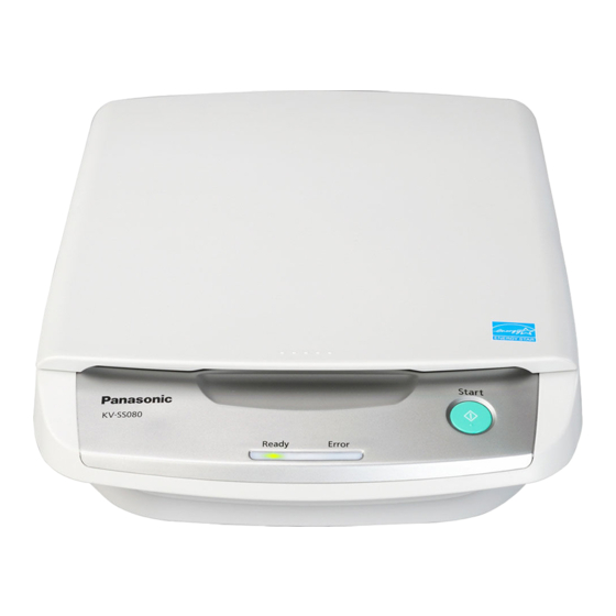
- Page 1 Order Number KM70811446CE Category Number H19 Flatbed Scanner KV-SS080 Model No. © Panasonic Communications Co., Ltd. 2008 Unau- thorized copying and distribution is a violation of law.
-
Page 2: Table Of Contents
TABLE OF CONTENTS PAGE 1 GENERAL PRECAUTIONS -------------------------------------3 1.1. Safety Precautions-----------------------------------------3 1.2. Standard for Repair Service -----------------------------3 1.3. For Service Technicians ----------------------------------3 1.4. About Lead Free Solder (PbF: Pb free) --------------3 1.5. About RoHS -------------------------------------------------4 2 SPECIFICATIONS -------------------------------------------------5 3 COMPONENT IDENTIFICATION ------------------------------7 3.1. -
Page 3: General Precautions
1 GENERAL PRECAUTIONS 1.1. Safety Precautions 1. Before servicing, unplug the power cord to prevent electrical shock hazard. 2. When replacing parts, use only manufacture’s recommended components for safety. 3. Check the condition of power cord. Replace if wear or damage is evident. 4. -
Page 4: About Rohs
1.4.1. Suggested Pb free solder We recommend you to use the following solder when re-soldering components for repair. Before using other Pb free solder than the following solder, make sure to confirm that the solder maker (you use) has the license agreement for Pb free solder. Supplier: Senju Metal Industry Co., Ltd. -
Page 5: Specifications
2 SPECIFICATIONS Item Model No. KV-SS080 Series Scanner Scanning Face Simplex Scanning Method CCD for Flatbed Background: Black / White (reversible sheet) Readout Gray 1.5 msec / line (300 dpi) 5.3 sec / page (A4, 300 dpi) Speed Color 1.5 msec / line (300 dpi) 5.3 sec / page (A4, 300 dpi) - Page 6 For 100 to 120 V : For KV-SS080 / SS080-T : For KV-SS080-U / SS080-A / SS080-K / SS080-CN : Scanning speed will differ depending on the test environment as well as depending on the host computer operating environment and applications used.
-
Page 7: Component Identification
3 COMPONENT IDENTIFICATION 3.1. Part Names... -
Page 8: Scanner Status
3.2. Scanner Status... -
Page 9: Installation
4 INSTALLATION 4.1. Minimum Space Requirements Be sure to maintain the recommended space requirements for proper ventilation. -
Page 10: Unlocking Carriage Lock
4.2. Unlocking Carriage Lock 1. Remove all packing tape. 2. Open the Document Cover. 3. Slide the LOCK / UNLOCK Selector in the direction of the arrow to release the Carriage lock. 4. Close the Document Cover. -
Page 11: Reversing Flatbed Sheet (As Required)
4.3. Reversing Flatbed Sheet (as required) When selecting white as the background color of scanned documents, perform the following: 1. Lift the Document Cover in the direction of the arrows to remove the cover. 2. Turn over the Document Cover. Carefully push the edge of the Flatbed Sheet nearest to the hinges in the direction of the arrow, and confirm that both sides of the sheet are released from the hooks on the cover. - Page 12 4. Turn over the Flatbed Sheet and set it into place. Be sure that the side edges of the sheet are inserted under the hooks on the Document Cover. 5. Turn over the Document Cover, and then attach the cover onto the unit, making sure to align the hinges with the hinge-mounting holes and to re-insert the hinges into place.
-
Page 13: Connecting Scanner To A Personal Computer
4.4. Connecting Scanner to a Personal Computer After connecting the Power Cord to the AC Adaptor, connect the AC Adaptor and the USB Cable to the back of the unit. Caution: 1. Only use the Power Cord, AC Adaptor, and USB Cable included with this scanner. 2. -
Page 14: System Requirements
4.5. System Requirements When using the scanner, the minimum system requirements are as follows. Computer ® ® PC/AT or compatible machine with a CD-ROM drive ® Pentium 3, 1 GHz or higher ® ® ® Windows 2000, Windows XP (32 bit only available), Windows Vista Interface USB 2.0 Memory... -
Page 15: Sectional Views
5 SECTIONAL VIEWS 5.1. Flatbed Block and Boards... -
Page 16: Mechanical Function
6 MECHANICAL FUNCTION 6.1. Carriage Drive Mechanism 1. When paper is set on the Flatbed Glass, and the scanning command is issued from the PC, the controller confirms its default position, and then the Carriage Motor rotates to drive the Scanning Unit. 2. -
Page 17: Maintenance
7 MAINTENANCE 7.1. Maintenance Clean the following parts at least once a week, or when 2,500 sheets have been scanned, whichever comes first. (1) Flatbed Glass (Top Cover Assy.) (2) Flatbed Sheet Note: The maintenance schedule was determined according to paper standards, which can vary greatly between users. Therefore, the schedule may vary by user. - Page 18 (3) Gently wipe the surface of the Flatbed Glass and Flatbed Sheet with a damp cloth that has been thoroughly wrung. Note: Use a neutral kitchen cleaner diluted with water for hard-to-clean stains. Do not use thinner, benzine or cleaners containing abra- sives as this may result in discoloration.
-
Page 19: Disassembly Instructions
8 DISASSEMBLY INSTRUCTIONS 8.1. Disassembly Flowchart The following flowcharts indicate the disassembly sequence for the Exterior, Mechanical parts, Unit Components, and Circuit Board assemblies When reassembling, perform the steps in the reverse order unless otherwise instructed in the Reassembling Notes. Note: •... -
Page 20: Disassembling
8.2. Disassembling 8.2.1. Document Cover 1. Lift the Document Cover in the direction of the arrows to remove the cover. - Page 21 8.2.2. Hinge Assy. L 1. Remove the Document Cover. (See 8.2.1.) 2. Remove the 6 screws (b), and then release the Hinge Assy. L from the Document Cover. Note: Hinge Assy. Hinge Assy. R: Only used for the right side Hinge Assy.
- Page 22 8.2.4. Top Cover Assy. 1. Remove the Document Cover. (See 8.2.1.) 2. Turn over the scanner unit, and then remove the 4 screws (f). 3. Lift the Top Cover Assy. in the direction of the arrows to release its assembly from the Bottom Cover. Note: Following this section, when proceeding to disassembling the parts mounted to the Bottom Cover...
- Page 23 8.2.6. Panel LED Cover 1. Remove the Panel Cover. (See 8.2.5.) 2. Unlock the hooks to release the Panel LED Cover from the Panel Cover. 8.2.7. Start Button 1. Remove the Top Cover Assy. (See 8.2.4.) 2. While releasing the 2 hooks from the guides in the direction of the arrows, pull the Start Button to carefully release the button from the Top Cover Assy.
- Page 24 8.2.8. PANEL Board 1. Remove the Top Cover Assy. (See 8.2.4.) 2. Remove the 2 screws (a) and 1 connector.
- Page 25 8.2.9. Lock / Unlock Selector 1. Remove the Top Cover Assy. (See 8.2.4.) 2. While releasing the tip of the Lock / Unlock Selector in the direction of the arrows (1), push the selector in the direction of the arrow (2) to remove it. 8.2.10.
- Page 26 8.2.12. Tension Plate Assembly 1. Remove the Motor Assy. (See 8.2.11.) 2. Release the Drive Belt from the pulley. 3. Remove the screw (d) and 2 screws (c). 4. Remove the spring to release the Tension Plate Assembly from the scanner. Reassembling Note: How to assemble the spring 1.
- Page 27 8.2.13. Shaft 1. Remove the Motor Assy. (See 8.2.11.) 2. Remove the 2 screws (c). 3. Pull out the Shaft carefully through the hole in the Scanning Unit in the direction of the arrow to separate the shaft from the Bottom Cover Assy. 8.2.14.
- Page 28 8.2.15. Drive Belt 1. Remove the Scanning Unit. (See 8.2.14.) 2. Remove the Drive Belt from the slot of the Scanning Unit. Note: Adjusting the belt tension 1. Perform the steps in the reverse order in Sec. 8.2.13, 8.2.14, and 8.2.15 to reassemble the Drive Belt, Scanning Unit, and Shaft.
-
Page 29: Service Utility & Self Test
Executing “ServiceUtility.exe” will allow you to operate all the functions found in this service utility software. Note • Be sure to connect only one scanner (KV-SS080) to a PC so that the main menu operation for KV-SS080 is displayed on the PC. -
Page 30: List Of Functions For Service Utility
9.2. List of Functions for Service Utility Service Utility item list is as follows. Item Purpose Remarks Scanner Status Used to indicate scanner status (Ready, Error, or Caution) Scanner information Used to indicate scanner information such as Model and Flatbed condition (Enable/ Disable) Scanner Condition Sleep Mode Used to set “Waiting Time”... -
Page 31: Operation
9.3. Operation This section describes each operation or status indication, according to the function item list shown in Sec.9.2. 9.3.1. Scanner Status This function indicates the scanner status, and updates it every few seconds. The status messages and their contents are as follows: Classification Status Message... - Page 32 9.3.2. Error Codes Classification and Error codes are as follows. Troubleshooting for this error message and codes is shown in Sec.10.2. Fig. 9.3.2.1 Classification Code Outline Classifica- Contents Classifica- Contents Classifica- Contents tion Code tion Code tion Code — — —...
- Page 33 9.3.3. Scanner Information This function provides various types of scanner information to the user or service-person. The main contents are as follows: 1. Model 2. Flatbed condition (Enable / Disable) 9.3.4. Scanner Condition Item Operation Default Remarks Sleep Mode 1. Click “Sleep Mode” on the main menu (Service Utility). 15 minutes For returning back to the 2.
- Page 34 9.3.5. Test Item Operation Default Remarks Flatbed LED 1. Click “Flatbed Test” on the main menu. Each LED (Red, Green) 2. Click “LED” on the "Flatbed Test" dialog box. turns on and/or off in a 3. Click “START” on the “LED” dialog box to start LED Test constant period as follows: that continues until “STOP”...
-
Page 35: Troubleshooting
10 TROUBLESHOOTING 10.1. Troubleshooting-1 (when no error message is displayed on PC) Phenomenon Possible Cause Check Point Remarks No power 1. Power Cord is not inserted to AC 1. Insert the Power Cord to the AC Adaptor, Adaptor correctly. correctly. 2. - Page 36 Phenomenon Possible Cause Check Point Remarks Start Button does not 1. Button's ON/OFF mechanical problem 1. When pushing the Start Button, check work properly. whether the button contacts the switch on the PANEL Board to be turned on. 2. Reassemble the button, and then re-attach the Top Cover Assy.
-
Page 37: Troubleshooting-2 (When An Error Message Is Displayed On Pc)
10.2. Troubleshooting-2 (when an error message is displayed on PC) Error Code Possible Cause Check Point Remarks Classification ST1 ST2 ST3 ST4 Code U90: B1 00 00 1. Lock / Unlock Selector is set 1. Set the Lock / Unlock Selector to Carriage is locked to "Lock". - Page 38 Error Code Possible Cause Check Point Remarks Classification ST1 ST2 ST3 ST4 Code F11: 1. Carriage-feed mechanism 1. Restart the scanner, and then execute Sent data time-out has some problems. "Carriage Drive" in Sec. 9.3.5 to error check whether this phenomenon is reproduced.
- Page 39 Error Code Possible Cause Check Point Remarks Classification ST1 ST2 ST3 ST4 Code F51: 0A 00 00 1. Carriage Home sensor does 1. Execute "Carriage Drive" in Sec. 9.3.5 Carriage home not work correctly. to check whether this phenomenon is sensor error reproduced.
- Page 40 Error Code Possible Cause Check Point Remarks Classification ST1 ST2 ST3 ST4 Code F61: 00 1. Power supply (+24 V) is not 1. Restart the scanner, and then execute White/ Dark properly supplied to the LED "Carriage Drive" in Sec. 9.3.5 to check calibration error Lamp included in the whether the same phenomenon is...
- Page 41 Error Code Possible Cause Check Point Remarks Classification ST1 ST2 ST3 ST4 Code F64: AF 00 00 1.Gamma data couldn't be 1. Restart the scanner, and then execute Gamma data Read / properly sent to CONTROL "Carriage Drive" in Sec. 9.3.5 to check Write error Board via USB interface.
- Page 42 Error Code Possible Cause Check Point Remarks Classification ST1 ST2 ST3 ST4 Code F66: B4 00 00 1. Carriage-feed mechanism 1. Execute "Carriage Drive" in Sec. 9.3.5 Carriage-feed error has some problems. to check whether this phenomenon is reproduced. 2. Check the mechanical condition of the belt and gears on the Motor Assy.
-
Page 43: Circuit Description
11 CIRCUIT DESCRIPTION 11.1. Block Diagram-1 (Image Processing) In this system, the ASIC controls the AFE, motor, SDRAM and amplifier: When receiving the start command from a PC, the ASIC performs some calibrations to check whether the scanner is ready to normally scan documents by activating the CCD and Carriage Motor. After that, the series of scanning processes start. -
Page 44: Block Diagram-2 (Board)
11.2. Block Diagram-2 (Board) -
Page 45: Explanation Of Connector
11.3. Explanation of Connector AC Adaptor - JP2 (CONTROL Board) Pin No. Signal Name Description AC Adaptor —- +24V Power 24 V —- DGND Digital Ground —- DGND Digital Ground JP3 (CONTROL Board) - Carriage Motor PIN NO. Signal Name Description Carriage Motor —... - Page 46 CN2 (CONTROL Board) - CN1 (CCD Board included in the Scanning Unit) PIN No. Signal Name Description LED_Current_Adjust1 LED current driver1 LED_Current_Adjust2 LED current driver2 LAMP_24V LED BAR 24 V power LAMPGND Ground +5 V power DGND Digital Ground DGND Digital Ground CCD_18V +18 V power...
-
Page 47: Parts Location And Mechanical Parts List
12 PARTS LOCATION AND MECHANICAL PARTS LIST... -
Page 48: Main Body
12.1. Main Body... - Page 49 Safety Ref. No. Part No. Part Name & Description Remarks PJ541080100A Top Cover ISO:PC+ABS PJ350018109A Hinge Assy L PJ350018110A Hinge Assy R PJ210529800A Flatbed Sheet PJ541079900A Panel Cover ISO:PC+ABS PJ541079800A LED Cover ISO:PC PJ541080000A START button ISO:PC+ABS PJ540536902A Lock Lever ISO:PC+ABS 350018103A Upper Cabinet...
-
Page 50: Packing
12.2. Packing... - Page 51 Operation Manual for KV-SS080-K PJ360379000A Operation Manual for KV-SS080-CN PJ330038000A AC Adaptor PJ230003815A USB Cable PJ230073400A AC Power Cord for KV-SS080 PJ230074000A AC Power Cord for KV-SS080-U(UK) PJ230073700A AC Power Cord for KV-SS080-U(Germany) PJ230073500A AC Power Cord for KV-SS080-K PJ230074100A...