Advertisement
Table of Contents
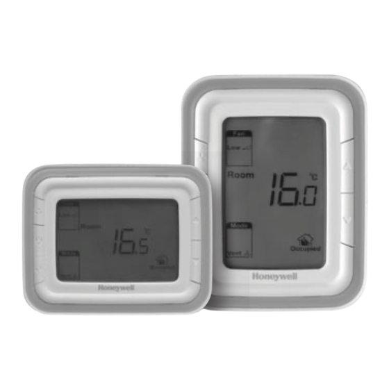
T6861 Series Large LCD Digital Thermostat
220 VAC
2-pipe fan coil control
Application
T6861 digital thermostats are designed for
application of 3-speed fan and valves in fan coil
system.
Including:
2-pipe cool only/heat only/manual changeover
Ventilation mode
Manual or automatic 3-speed fan control
Water valve control
Fan speed can be selected to automatic or manual
3-speed control mode.
In ventilation mode, fan only support manual speed
control.
Model summary
Horizontal/
Model
Vertical
T6861H2BB-M
Horizontal
T6861H2WB-M
T6861V2BB-M
Vertical
T6861V2WB-M
T6861H2GG-M
Horizontal
T6861H2WG-M
T6861V2GG-M
Vertical
T6861V2WG-M
Note: Horizontal models are taken as samples for display, operation and installation pictures shown in below parts.
APH07CH04 - R2001EN
Time
Backlight Color Ring
on/off
Blue
Blue
Y
White
Blue
Blue
Y
White
Green
Green
Y
White
Green
Green
Y
White
Features
• Super modern appearance design, suitable for
office, hotel and residential building
• Horizontal and vertical model available for variant
application
• Slim design, direct installation on 3" x 3" size box
• Stylish and elegant blue/green backlight with blue/
green/ white colour ring
• Big LCD display with English and icons
• Easy to install and set-up
• Time on/off function
• Selectable room temperature or setpoint display
• Manual or automatic fan speed selection
• Energy saving mode activation by button press or
dry contact (key card)
• Cycle per Hour (CPH) function
• Adjustment of display room temperature
• Temperature unit either
• User setting can be kept when power off
• Freezing protection function available
• Lock or unlock keys or part of keys in Installer Set-
up
• Heat and cool setpoint limitation for energy saving
2-pipe/
Power supply
Energy
4-pipe
Saving
(V)
2
220
2
220
2
220
2
220
Data sheet
o
o
C or
F
Manual/
Ventilation
Automatic Fan
Y
Y
Y
Y
Y
Y
Y
Y
Y
Y
Y
Y
Advertisement
Table of Contents

Related Manuals for Honeywell T6861 Series


Summary of Contents for Honeywell T6861 Series
- Page 1 T6861 Series Large LCD Digital Thermostat 220 VAC 2-pipe fan coil control Data sheet Features • Super modern appearance design, suitable for office, hotel and residential building • Horizontal and vertical model available for variant application • Slim design, direct installation on 3" x 3" size box •...
-
Page 2: Lcd Display
Mechanical design Fan Operation Thermostat appearnce DIGITAL DISPLAY FAN BUTTON UP BUTTON POWER BUTTON DOWN BUTTON MODE BUTTON PRESS THE FAN BUTTON TO SELECT LOW, MED, HIGH OR AUTO LCD display Fan can be selected as manual or automatic 3-speed operation. In Manual mode, the fan is switched to the selected speed via control output Gh, Gm, Gl. -
Page 3: Keypad Lock
Time on/off Ventilation mode If the thermostat is off, hold power button for 3 Press mode button to enter ventilation mode. In seconds, system will be time on mode. If the ventilation mode, no output for valve while the fan thermostat is on, hold power button for 3 seconds, will operate according to selected fan speed. -
Page 4: Terminal Designations
Terminal Designations Freezing protection mode Freezing protection can be selected as disabled (default) or enabled. In freezing protection mode Terminal Description (no such mode in cool only application), when thermostat is in OFF mode while the acquired AC Power temperature is below 6 C, the thermostat will start heat mode until the temperature rises to 8 C or the... -
Page 5: Installation And Commissioning
Installation & Commissioning Application 2: 2 pipes Cool only wiring diagram Install the thermostat about 5 feet (1.5m) above the floor in an area with good air circulation at average temperature. Cool valve Remote Setback Fig.2.3 Typical wiring for ON/OFF control in 2 pipe cooling only (VC4013) Do not install in locations where the thermostat can Cool valve be affected by:... -
Page 6: Installer System Test
Installer system test 3 Place Back cover over junction box, insert and tighten mounting screws. After completing the installer setup above, press the button again to begin a system test Follow the procedure below to test the heating and cooling and fan system. System test No. -
Page 7: Troubleshooting Tips
Troubleshooting Tips Setup Function Settings & Options Number Description Possible Options If… Then… 0 Heat only ♦ Set the mode to Heat by pressing the Mode button. System type 1 Cool only Heating system ♦ Check that the heat temperature setting is set above does not turn the room temperature and “Heat On”...