Table of Contents
Advertisement
Quick Links
Operation
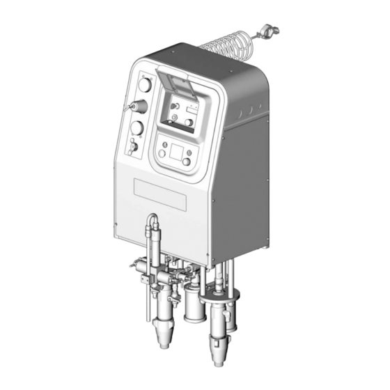
Self-contained, single color, electronic plural component paint proportioner.
For professional use only.
Important Safety Instructions
Read all warnings and instructions in this manual.
Save these instructions.
See page 3 for model information, including maxi-
mum working pressure and approvals.
309908G
ENG
TI4909a
Advertisement
Table of Contents

Related Manuals for Graco ProMix Easy Series


Summary of Contents for Graco ProMix Easy Series
- Page 1 Operation 309908G Self-contained, single color, electronic plural component paint proportioner. For professional use only. Important Safety Instructions Read all warnings and instructions in this manual. Save these instructions. See page 3 for model information, including maxi- mum working pressure and approvals. TI4909a...
-
Page 2: Table Of Contents
Pump Test ....... 22 Graco Information ......40 Manual Conventions Warnings in the instruction sections (such as “Instal-... -
Page 3: Promix Easy Models
ProMix Easy Models ProMix Easy Models WARNING Do not install equipment approved only for non-haz- ardous location in a hazardous area. Substitution of components may impair intrinsic safety and cause per- sonal injury. Read page 5. Approved for Hazardous Location Class I, Div 1, Group D (North America);... -
Page 4: Related Manuals
Related Manuals Related Manuals Component Manuals in English This manual available in the following languages: Manual Description Manual Language 309908 ProMix Easy Operation 309908 English 309909 ProMix Easy Repair-Parts 310679 French 310654 Fluid Mix Manifold 310681 Spanish 310655 Dispense Valve 310683 German 310662... -
Page 5: Warnings
Warnings Warnings The following general warnings are related to the safe setup, use grounding, maintenance, and repair of this equip- ment. Additional more specific warnings may be found throughout the text of this manual where applicable. Warning FIRE AND EXPLOSION HAZARD Flammable fumes, such as solvent and paint fumes, in work area can ignite or explode. - Page 6 Do not alter or modify equipment. • For professional use only. • Use equipment only for its intended purpose. Call your Graco distributor for information. • Route hoses and cables away from traffic areas, sharp edges, moving parts, and hot surfaces. •...
-
Page 7: Overview
Overview Overview Usage 3. Stop button to terminate functions. The ProMix Easy can mix most two-component paints. It is not for use with “quick-setting” paints (those with a pot 4. Key switch to change ratio, pot life time, pot life vol- life of less than 5 minutes) without modification. -
Page 8: Installation
. 3 is not an actual ProMix Easy non-IS units operate with 93-250 Vac, system design. Contact your Graco distributor for assis- 50/60 Hz input power, with a maximum 1.2 amp current tance in designing your system. Be sure all accessories draw. - Page 9 Installation S (Ref) TI4791b . 3. Typical Installation (Wall Mount, Air-Assisted Unit Shown) Key for F ProMix Easy Plural Component Proportioner Air-Assisted Spray Gun User Interface (see page 7) Air Line Shutoff Valve Mix Manifold Proportioner Air Supply LIne Bleed-Type Main Air Shutoff Valve Ground Wire Air Supply Pressure Gauge Pump Air Regulator (pump-based units only)
-
Page 10: Air Controls
Installation Air Controls • Sampling valves (H ), to batch dispense or test pumps/meters. See F . 3. • Solvent purge valves (J ) allow solvent to • Bleed-type main air shutoff valve (D), to shutoff enter the fluid manifold. all air to ProMix Easy (including controller power). - Page 11 Installation Component A Dispense Component B Dispense Solenoid A opens dispense valve A. The correct dose of Solenoid B opens dispense valve B. The correct dose of component A flows into the integrator (Z). Solenoid A component B flows into the integrator (Z) and is aligned closes dispense valve A.
-
Page 12: Setup
Setup Setup Pump-based models only: Fill pumps A and B pack- WARNING ing nuts with throat seal liquid (TSL). Do not install equipment approved only for non-haz- ardous location in a hazardous area. Substitution of components may impair intrinsic safety and cause per- sonal injury. - Page 13 Setup Flush and prime system. See pages 16 and 20. Run Pump-based models only: Set air regulator to 0. Pump Test, page 22 to check ratio accuracy. Open main air shutoff valve. When starting up, dis- play will show “88888”, then software revision, then current ratio (if set to Setup ratio.
-
Page 14: Pressure Relief Procedure
Pressure Relief Procedure Pressure Relief Procedure Engage trigger lock. WARNING Relieve pressure from fluid manifold to gun whenever you stop spraying and before servicing gun or remov- ing spray tip. In addition, relieve pressure from pump to fluid mani- fold at end of day and before cleaning, checking, or servicing pump, manifold, or fluid line accessories or transporting equipment. -
Page 15: Pump To Fluid Manifold
Pressure Relief Procedure Pump to Fluid Manifold Open sampling valve A slowly to bleed off pressure. Indicator A will stay on for 5 sec after Pump A reaches Park position, then go off. Close shutoff valves G and G Pump air supply pressure must be sufficient to Place waste container under sampling valves H cause pumps to stroke to bottom-most position and H... -
Page 16: Flushing
Flushing Flushing Fluid Manifold Flushing There are times when you only want to flush the fluid manifold, such as: • breaks in spraying Using Solvent Pump • overnight shutdown • end of potlife Follow Pressure Relief Procedure, page 14. Engage trigger lock. Remove spray tip. In this manual, that procedure is referred to as Fluid Manifold Flushing. - Page 17 Flushing Disengage trigger lock and trigger gun into a Disengage trigger lock, and flush through gun until grounded pail. Flush out about 1 pint (500 cc) of clean solvent flows. Engage trigger lock. mixed material. Engage trigger lock. Close solvent purge valves J and J Trigger gun to relieve solvent pressure.
-
Page 18: Full System Flushing
Flushing Full System Flushing Trigger gun into grounded pail. Dispense about 1 Follow Pressure Relief Procedure, page 14. pint (500 cc) of material, then press Engage trigger lock. Set air regulator to 0, and close main air shutoff valve. Remove spray tip and soak in If the pump does not start when you trigger the solvent. - Page 19 Flushing Open solvent purge valve J . Trigger gun into grounded pail and flush until clean solvent flows Turn function knob to B . Press from gun. Ensure shutoff valve G is open. Open sampling valve H slowly. Pump B will run for 12 cycles, then stop.
-
Page 20: Priming
Priming Priming Do not install the gun spray tip yet. Use the lowest Place a container under each sampling valve. Open possible pressure while priming, to avoid splash- sampling valve H slowly. ing. Connect A and B fluid supply hoses to A and B pumps/meters. - Page 21 Priming When side A is primed, set air regulator to 0. Press . Close sampling valve H . Open sampling valve slowly. Turn function knob to B . Press . Turn up air regulator slowly until pump B starts. When side B is primed, press .
-
Page 22: Pump Test
Pump Test Pump Test Follow this procedure the first time system is operated Dispense fluid A: (after flushing and priming) and whenever you need to check whether pumps are on ratio. Close fluid shutoff valves (G and G ) and sam- pling valves (H and H The following table shows the volume dispensed during... - Page 23 Pump Test Dispense fluid B as follows: Place a clean 1 quart (1000 cc) container under sampling valve H Slowly open and adjust sampling valve H achieve desired flow. The pump stops automati- cally after 5 cycles. Indicator B turns off. Close sampling valve H Compare fluid amounts in the containers;...
-
Page 24: Spraying
Spraying Spraying Close sampling valves H and H . Open shutoff Engage trigger lock. Press valves G and G Follow Pressure Relief Procedure, page 14. Engage trigger lock. Install tip on gun. Turn function knob to . Press TI1948A Adjust air regulator to the necessary spraying pres- sure. -
Page 25: Batch Dispense Or Ratio Check
Batch Dispense or Ratio Check Batch Dispense or Slowly open and adjust sampling valve H achieve desired flow. The pump stops automati- Ratio Check cally when dispense is complete. Indicator A turns off, indicator B comes on. Batch dispense is always 1 pint (500 cc) of total volume, regardless of ratio setting. -
Page 26: Pot Life Timer
Pot Life Timer Pot Life Timer Pot Life Reset Volume To Display Pot Life Time Left (in minutes) The timer resets when the total spray volume exceeds Turn the function knob to the pot life reset volume. To change reset value, hold down . -
Page 27: Recirculation Setting
Recirculation Setting Recirculation Setting Fluid can be circulated up to the mix manifold with the addition of Graco’s Circulation Kit. Consult your distribu- tor. During recirculation only the pump runs; A and B dispense valves do not operate. Material pumped in recirculation mode is not counted by the total- izer. -
Page 28: Shutdown
Shutdown Shutdown Follow this procedure before prolonged shutdown or servicing equipment. Follow Pressure Relief Procedure, page 14. Engage trigger lock, set air regulator to 0, and close main air shutoff valve. Remove spray tip. TI1948A TI1948A Follow Flushing, page 16. Follow Pressure Relief Procedure, pages 14 and 15. -
Page 29: Recalibrate Pump-Based System
Recalibrate Pump-based System Recalibrate Pump-based Calibrate Pump Sensor System Trigger gun into a pail or open sampling valve H Follow steps 1-9 whenever the main circuit board, soft- ware, or sensor is replaced, or when Alarm 8 occurs (refer to page 32). If sensor only needs recalibration, fol- low steps 7-9. -
Page 30: Recalibrate Meter-Based System
NOTE: If the main control board is replaced on units that use a flow meter, the flow meter calibra- tion data must be set using a PC and a Data Download Kit (Graco P/N 248403 for hazardous locations or Graco P/N 248404 for non-hazardous locations). -
Page 31: Set Meter K-Factor
Recalibrate Meter-based System Component B dispensed volume will display. Com- pare displayed volume with actual volume in con- tainer B. For no change, press , then release. To change display, press and hold . Turn key to change display to match actual volume (left to decrease, right to increase). -
Page 32: Alarms
Alarms Alarms Indicates error where audible alarm sounds once briefly. • An alarm condition will shutdown equipment. • See ProMix Easy Repair manual for trouble- Indicates error where audible alarm sound pulses. shooting and repair. Code Alarm Active Problem Cause Startup Errors Sensor Error A* Always... - Page 33 Alarms Code Alarm Active Problem Cause Operating Errors (con- tinued) High Ratio (units with Spray Mix ratio higher than Flow rate too high meter[s] only) Target + Tolerance Slow actuation of dispense valve A or B Low Ratio (units with Spray Mix ratio lower than Clogged flow meter...
-
Page 34: Performance Charts
Performance Charts Performance Charts 2.5:1 Ratio UltraMix Pump Tested with 10W oil (1.75, 17.5) 100 psi (0.7 MPa, 7 (1.4, 14.0) (1.05, 10.5) 70 psi (0.48 MPa, 4.8 (0.7, 7.0) (0.35, 3.5) 40 psi (0.28 MPa, 2.8 0.1 (0.38) 0.2 (0.76) 0.3 (1.14) 0.4 (1.52) 0.5 (1.90) -
Page 35: 34:1 Ratio Hydramix Pump
Performance Charts 34:1 Ratio HydraMix Pump Tested with 10W oil 3500 (24.5, 245) 3000 100 psi (0.7 MPa, 7 (21.0, 210) 2500 (17.5, 175) 2000 70 psi (0.48 MPa, 4.8 (14.0, 140) 1500 (10.5, 105) 40 psi (0.28 MPa, 2.8 1000 (7.0, 70) (3.5, 35) -
Page 36: Technical Data
Technical Data Technical Data Mix ratio range ....... . . 0.1:1-10:1 (in 0.1 increments), pump-based systems 0.1:1-30:1 (in 0.1 increments), meter-based systems Ratio tolerance range . - Page 37 Technical Data External Power Supply Requirements ....93-250 Vac, 50/60 Hz, 1.2 amps maximum draw 15 amp maximum circuit breaker required 14 AWG power supply wire gauge Environmental Conditions Rating .
- Page 38 Technical Data 309908G...
-
Page 39: Dimensions
Dimensions Dimensions Cart model (width x height x depth) ....31 x 56 x 29 in. (787 x 1422 x 737 mm) Air inlet size ....... . 1/2 npt(f) Fluid inlet size. -
Page 40: Graco Standard Warranty
With the exception of any special, extended, or limited warranty published by Graco, Graco will, for a period of twelve months from the date of sale, repair or replace any part of the equipment determined by Graco to be defective.